extronics iSCANPS User manual

Extronics Limited
1 Dalton Way, Midpoint 18, Middlewich, Cheshire, UK. CW10 0HU
Tel: +44 (0) 845 277 5000 Fax: +44 (0)845 277 4000 E-mail: [email protected] Web: www.extronics.com 1
Operating Instructions
Power supply module
iSCANPS
Revision date: 09.06.2020

Extronics Limited
1 Dalton Way, Midpoint 18, Middlewich, Cheshire, UK. CW10 0HU
Tel: +44 (0) 845 277 5000 Fax: +44 (0)845 277 4000 E-mail: [email protected] Web: www.extronics.com 2
Contents
Revision control ......................................................................................................................................2
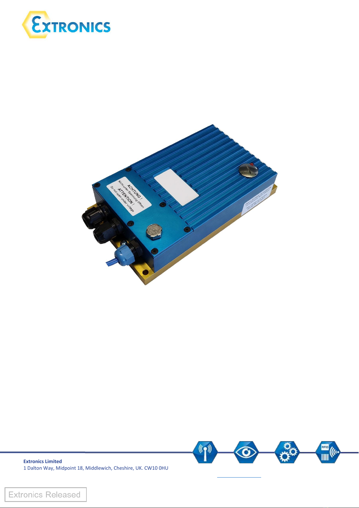
1. iSCANPS product range overview ...................................................................................................3
2. Important notes on the operating instructions..............................................................................4
2.1 Safety information ..................................................................................................................4
2.2 Notes on the operating instructions.......................................................................................4
2.3 General notes of caution ........................................................................................................5
3. Product Information .......................................................................................................................7
3.1 Manufacturer..........................................................................................................................7
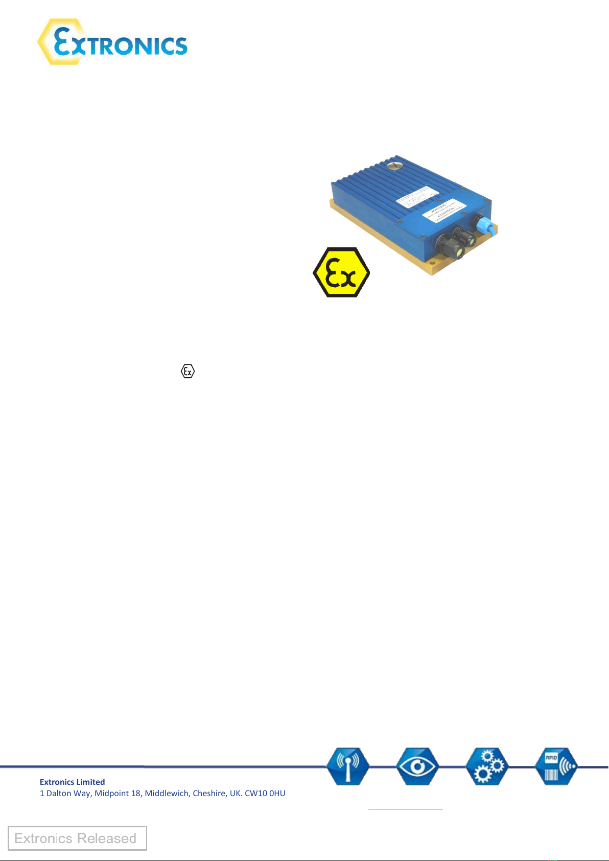
3.2 Certification.............................................................................................................................7
3.3 Serial numbers ........................................................................................................................7
3.4 Technical data.........................................................................................................................8
3.5 Type numbers .......................................................................................................................10
4 Operating the power supply module............................................................................................11
4.1 Power supply design ...................................................................................................................11
4.2 Pin assignment in the Ex e connection box.................................................................................12
4.3 Pin assignment in the Ex i connection box with RS232 interface ...............................................13
4.4 Pin assignment in the Ex i connection box with RS232 interface ...............................................14
Revision control
Document Number 416239, revision 8. Refer to Extronics DDM for release status.
© This document is copyright Extronics Limited 2020.
Extronics reserve the right to change this document and its content without notice. The latest
version applies.

Extronics Limited
1 Dalton Way, Midpoint 18, Middlewich, Cheshire, UK. CW10 0HU
Tel: +44 (0) 845 277 5000 Fax: +44 (0)845 277 4000 E-mail: [email protected] Web: www.extronics.com 3
1. iSCANPS product range overview
Power supply module
Standard 1D iSCAN211
Standard and stacked PDF
iSCAN211PDF
iSCAN211EXB
iSCAN2XXCAB5
iSCAN2XXCAB6
iSCAN2XXCAB7
iSCAN2XXCAB8
iSCAN2XXCAB9
iSCAN2XXCAB10
iSCANPS1
iSCANPS2
iSCANPS3
iSCANPS4
Standard 1D, stacked PDF, and
2D ISCAN2112D
iSCAN201EXB2D
iSCAN2XXCAB5
iSCAN2XXCAB6
iSCAN2XXCAB7
iSCAN2XXCAB8
iSCAN2XXCAB9
iSCAN2XXCAB10
iSCANPS1
iSCANPS2
iSCANPS3
iSCANPS4
Standard 1D iSCAN101
Standard and stacked PDF
iSCAN101PDF
iSCAN101CAB1
iSCAN101CAB2
iSCAN101CAB3
iSCAN101CAB4
iSCAN101CAB5
iSCAN101CAB6
iSCANPS1
iSCANPS2
iSCANPS3
iSCANPS4
Standard 1D, stacked PDF, and
2D ISCAN1112D
iSCAN101CAB1
iSCAN101CAB2
iSCAN101CAB3
iSCAN101CAB4
iSCAN101CAB5
iSCAN101CAB6
iSCANPS5
iSCANPS6
iSCANPS7
iSCANPS8

Extronics Limited
1 Dalton Way, Midpoint 18, Middlewich, Cheshire, UK. CW10 0HU
Tel: +44 (0) 845 277 5000 Fax: +44 (0)845 277 4000 E-mail: [email protected] Web: www.extronics.com 4
2. Important notes on the operating instructions
2.1 Safety information
Warnings are highlighted by a special symbol and a different font colour:
Danger
Non-compliance may result in life-threatening situations.
This warning must be heeded.
Warning
This type of warning concerns dangerous situations that may result in minor injuries.
Info
Important and helpful notes and information.
2.2 Notes on the operating instructions
Before starting up the equipment please read the Manual thoroughly.
The Operating Instructions contain important information on functionality as well as safety rules.
If these are not heeded, normal operations within hazardous areas cannot be guaranteed.
The notes contained in this manual are important for starting up and operating the product.
These instructions may be updated at any time. Extronics Limited reserves the right to make changes
to this document. Before they use the product, users must ensure that they have the most up-to-
date version of the operating instructions. To make sure this is the case, please check Extronics’
website, www.extronics.com, or contact one of the company's staff.
The drawings contained in these operating instructions are for illustration purposes only and may
differ somewhat from the actual design.
No changes may be made to the device that were not intended or approved
by Extronics Limited.

Extronics Limited
1 Dalton Way, Midpoint 18, Middlewich, Cheshire, UK. CW10 0HU
Tel: +44 (0) 845 277 5000 Fax: +44 (0)845 277 4000 E-mail: [email protected] Web: www.extronics.com 5
If the handheld scanner is not used properly, the operating permission for hazardous areas may lapse
for the device in question.
Non-adherence to the instructions will void any warranty.
For the full commission of the handheld scanner, the programming information contained
in the manual issued by SICK AG (www.SICK.com) is also required.
2.3 General notes of caution
Caution / Notes
•The devices may only be operated when fully assembled.
•In hazardous areas, the devices must not be wiped or cleaned with a dry
cloth.
•The device must be switched off immediately if it is likely that it can no
longer be operated safely as a result of damaging impact or general
peculiarities (such as ingress of water or other fluids, temperatures outside
of the specified range, etc.).
•General statutory requirements or health and safety rules and accident
prevention guidelines and environmental laws must be adhered to (e.g.
the German Occupational Health and Safety regulation).
•Users must not open the device.
•Users must not make any changes to the device. Components may not be
exchanged or replaced. If non-specified components are used, explosion
protection is no longer guaranteed.
•Ensure safe handling with firm footing and sufficient room for movement.
•If the enclosure is in any way damaged the device must be removed from
the hazardous area immediately.
•In accordance with IEC 60079-19 and IEC 60079-17, operators of electrical
installation in hazardous areas are obliged to have them serviced by
qualified electricians.
•Do not insert any sharp objects into the enclosure or any other openings of
the handheld barcode scanner. Any openings at the device may not be
covered or blocked.
•The device and any accessories must be properly disposed of, i.e. as legally
specified, for example by a certified company.

Extronics Limited
1 Dalton Way, Midpoint 18, Middlewich, Cheshire, UK. CW10 0HU
Tel: +44 (0) 845 277 5000 Fax: +44 (0)845 277 4000 E-mail: [email protected] Web: www.extronics.com 6
Notes on
installation
•Electrical plants are subject to certain regulations concerning installation
and operation (e.g. RL 99/92/EG, RL 94/9EG, or the national rules such as
IEC 60 079-14 and VDE 0100).
•In the hazardous area it is the operator's responsibility to carry out any
repair and maintenance in compliance with applicable rules.
Caution
on laser devices
Devices fitted with laser fall under standards US 21 CFR 1040.10 and EN 60825-
The laser's classification is stated on a plate affixed to the device. Class 1
lasers are deemed inherently safe during normal use, but users must not look
directly into the light source. The following declaration is required by American
and international laws:
Usage of control elements, adaptations or the use of procedures that differ
from these instructions may result in a dangerous exposure to laser beams.
Class 2 lasers use a visible low-voltage LED. As with any source of bright light,
such as the sun, the user should avoid looking directly into the light. Brief
exposure to a class 2 laser is deemed not dangerous.
Maintenance
Provided the device is operated and assembled according to instructions and
the ambient requirements are being met continuous maintenance is not
necessary.
Servicing
Operators of electric equipment in hazardous areas are obliged to have them
serviced by qualified electricians (IEC 60079-19 and IEC 60079-17).
Repairs
Repairs may only be carried out by the manufacturer or by persons trained and
commissioned for this purpose by the manufacturer.
The device is closed ex-factory. It may only be opened in the factory by specifically trained
personnel.
Software
installation
For instructions on how to install the software at the PC please refer to the
manual issued by SICK.
Operation
Before operating the device, you must ensure that all necessary components
are available.
Outside
Operation
A housing around the iSCANPS is needed if it is used outside.
Notice the regulations concerning installation and operation.

Extronics Limited
1 Dalton Way, Midpoint 18, Middlewich, Cheshire, UK. CW10 0HU
Tel: +44 (0) 845 277 5000 Fax: +44 (0)845 277 4000 E-mail: [email protected] Web: www.extronics.com 7
3. Product Information
3.1 Manufacturer
Extronics Limited
1 Dalton Way
Midpoint 18
Middlewich
CW10 0HU
3.2 Certification
3.3 Serial numbers
Serial key:
Year of manufacture
(2 numbers)
Serial number
(4 numbers)
Example:
19001
iSCANPSx:
II 2 G Ex eb q [ib IIC/IIB] IIC T4 Gb
II 2 D Ex tb [ib] IIIC T135C Db
Ta=-25°C to 60°C
Test certificate
IBExU15ATEX1082
IECEx IBE 15.0022
Directive
2014/34/EU
Standards
EN IEC 60079-0:2018
EN 60079-5:2015
EN IEC 60079-7:2015/A1:2018
EN 60079-11:2012
EN 60079-31:2014
Protection rating
IP64

Extronics Limited
1 Dalton Way, Midpoint 18, Middlewich, Cheshire, UK. CW10 0HU
Tel: +44 (0) 845 277 5000 Fax: +44 (0)845 277 4000 E-mail: [email protected] Web: www.extronics.com 8
3.4 Technical data
Non-intrinsically safe
power supply circuit:
•rated voltage
Un
DC +24 V ± 25 %
•power input
P
= ca. 3.7W (max. 7.1W)
iSCANPS1 and 2:
iSCANPS3 and 4:
•rated voltage
Un
AC 90 V to 253 V, 50 - 60 Hz
•power input
P
= ca. 4W (max. 16W)
Non-intrinsically safe data
circuit:
RS232
±12 V / 4 mA
RS422
+12 V / -7 V / 4 mA
USB
+5 V / 68 mA
Nominal data (RS232):
•maximum fault voltage
Um
253V
•maximum output voltage
Uo
4.9V
•maximum output current
Io
440mA
•maximum output power
Po
1.17W (trapezoidal
characteristic)
•maximum external capacitance
Co
Ex ib IIC: ≤113 µF
Ex ib IIB: ≤1000 µF
•maximum external inductance
Lo
Ex ib IIC: 0.10 mH (Co=0)
Ex ib IIB: 1.30 mH (Co=0)
iSCANPS1 and 3 (RS232 interface, output current 240mA):
iSCANPS5 and 7 (RS232 interface, output current 600mA):
•maximum fault voltage
Um
253V
•maximum output voltage
Uo
5,3V
•maximum output current
Io
1125mA
•maximum output power
Po
3.16W (trapezoidal
characteristic)
•maximum external capacitance
Co
Ex ib IIC: <68 µF (Lo=0)
Ex ib IIB: ≤1000 µF (Lo=0)
•maximum external inductance
Lo
Ex ib IIC: 0.1 mH (Co=0)
Ex ib IIB: 0.53 mH (Co=0)

Extronics Limited
1 Dalton Way, Midpoint 18, Middlewich, Cheshire, UK. CW10 0HU
Tel: +44 (0) 845 277 5000 Fax: +44 (0)845 277 4000 E-mail: [email protected] Web: www.extronics.com 9
Nominal data (USB),
intrinsically safe supply
circuit:
There must be potential
equalization, intrinsically
safe circuit grounded!
iSCANPS2 and 4 (RS232 interface, output current 240mA):
•maximum fault voltage
Um
253V
•maximum output voltage
Uo
4.9V
•maximum output current
Io
440mA
•maximum output power
Po
1.17W (trapezoidal
characteristic)
•maximum external capacitance
Co
Ex ib IIC: <113 µF (Lo=0)
Ex ib IIB: ≤1000 µF (Lo=0)
•maximum external inductance
Lo
Ex ib IIC: 0.10 mH (Co=0)
Ex ib IIB: 1.30 mH (Co=0)
iSCANPS6 and 8 (RS232 interface, output current 600mA):
Nominal data (USB),
intrinsically safe data
circuit:
•maximum fault voltage
Um
253V
•maximum output voltage
UO
D+/D-
5,3V
•maximum output current
IO
D+/D-
1125mA
•maximum output power
PO
D+/D-
3.16W (trapezoidal
characteristic)
•maximum external capacitance
Co
Ex ib IIC: <68 µF (Lo=0)
Ex ib IIB: ≤1000 µF (Lo=0)
•maximum external inductance
Lo
Ex ib IIC: 0.1 mH (Co=0)
Ex ib IIB: 0.53 mH (Co=0)
Pin assignment data
circuit, non-intrinsically
safe data circuit:
RS232
X5 (TxD)
X4 (GND)
RS232 ± 12V / 4mA
RS422
X7 (T+)
X8 (T-)
X6 (TE)
RS422 ± 12V / -7V / 4mA
USB
X5 (screen)
X4 (GND)
X6 (NV)
X7 (D+ 2MA)
X8 (D- 2MA)
USB +5V / 68 mA

Extronics Limited
1 Dalton Way, Midpoint 18, Middlewich, Cheshire, UK. CW10 0HU
Tel: +44 (0) 845 277 5000 Fax: +44 (0)845 277 4000 E-mail: [email protected] Web: www.extronics.com 10
3.5 Type numbers
RS232 devices
iSCANPS1
DC 24 V with RS232 interface, Ua= 4.9 V / Ia=240 mA
iSCANPS5
DC 24 V with RS232 interface, Ua= 4.9 V / Ia=600 mA
iSCANPS3
AC 90 to 253 V with RS232 interface, Ua= 4.9 V / Ia=240 mA
iSCANPS7
AC 90 to 253 V with RS232 interface, Ua= 4.9 V / Ia=600 mA
USB devices
iSCANPS2
DC 24 V with USB interface, Ua= 4.9 V / Ia=240 mA
iSCANPS6
DC 24 V with USB interface, Ua= 4.9 V / Ia=600 mA
iSCANPS4
AC 90 up to 253 V with USB interface, Ua= 4.9 V / Ia=240 mA
iSCANPS8
AC 90 up to 253 V with USB interface, Ua= 4.9 V / Ia=600 mA
Pin assignment data
circuit, non-intrinsically
safe data circuit:
RS232
X9 (RxD)
X10 (GND)
Ui= 5.5V DC
USB
X9 (D+ 2SL)
X10 (D- 2SL)
X11 (GND/PE)
UO D+/ D- = 4.9 V
IO D+/ D- = 20 mA per data cable
PO D+/ D- = 24 mW per data cable
linear characteristic
External connection cable:
Data cable :
USB: 0.2 –2.5 mm2, 3-wire
RS232/RS422: 0.2 –2.5 mm24-wire
Power supply cable :
USB: 1.5 –2.5 mm2, 3-wire (miniature circuit breaker has to be connected
previously)
The current rating of the connection cables must be checked before use.
Dimensions:
140 mm x 250 mm x 56 mm (W x H x D)
Weight:
3.1 kg without connection cable
Ambient temperature:
-25°C to +60°C

Extronics Limited
1 Dalton Way, Midpoint 18, Middlewich, Cheshire, UK. CW10 0HU
Tel: +44 (0) 845 277 5000 Fax: +44 (0)845 277 4000 E-mail: [email protected] Web: www.extronics.com 11
4Operating the power supply module
4.1 Power supply design
Use the four fixing holes at the corner of the base plate
(see diagram) to mount the power supply onto a firm
surface.
The holes have a diameter of 7mm each.
The equipotential bonding connection (M 5 x 10) is
located at the front and back of the power supply.
Equipotential bonding is required for the
entire installation of the intrinsically safe
circuits.
Terminal connection box underneath cover.
Cable gland M16 x 1.5 for appliance.
Cable gland M16 x 1.5 for data transfer.
Cable gland M20 x 1.5 for voltage supply.
Ex e connection box for connection of voltage supply.
Ex i connection box for connection of appliances.
Do not remove the breather!
The flat seal of the Ex e connection box has to
be reinstalled after it was opened.

Extronics Limited
1 Dalton Way, Midpoint 18, Middlewich, Cheshire, UK. CW10 0HU
Tel: +44 (0) 845 277 5000 Fax: +44 (0)845 277 4000 E-mail: [email protected] Web: www.extronics.com 12
4.2 Pin assignment in the Ex e connection box
Pin assignment for the supply with RS232 interface:
Terminal definition
Terminal number
Description
Type numbers
+ / - L
X1
L = AC 100 V to 250 V
+ = DC24 V
iSCANPS1
iSCANPS5
iSCANPS3
iSCANPS7
- / N
X2
N Neutral conductor
-minus
iSCANPS1
iSCANPS5
iSCANPS3
iSCANPS7
PE
X3
PE
GND
X4
RS232
TxD
X5
RS232
Shield
X6
RS232/RS422
T+
X7
RS422
T-
X8
RS422
Pin assignment of supply with USB interface:
Terminal definition
Terminal number
Description
Type numbers
+ / - L
X1
L = AC 100 V to 250 V
+ = DC24 V
iSCANPS2
iSCANPS6
iSCANPS4
iSCANPS8
- / N
X2
N Neutral conductor
-minus
iSCANPS2
iSCANPS6
iSCANPS4
iSCANPS8
PE
X3
PE
GND
X4
USB
Shield
X5
USB
NC
X6
D+
X7
USB
D-
X8
USB

Extronics Limited
1 Dalton Way, Midpoint 18, Middlewich, Cheshire, UK. CW10 0HU
Tel: +44 (0) 845 277 5000 Fax: +44 (0)845 277 4000 E-mail: [email protected] Web: www.extronics.com 13
4.3 Pin assignment in the Ex i connection box with RS232 interface
The terminal assignment is located underneath the removable cover at the
front of the power supply.
Caution! Do not open enclosure in hazardous area!
Before operating the device in a hazardous area, you have to
ensure that the enclosure has been closed fully, the flat seal is
reinstalled and all screws have been tightened.
Any changes to the wiring may only be carried out by trained
staff.
Pin assignment in the Ex i connection box RS232:
Power supply Type: iSCANPS1, 3, 5, 7
Prepared
Connection coupling
Connection box
Pin
Wire
Definition
Number
3
3
RxD
X9
GND
X10
PE
X11
2
2
GND
X12
1
1
+UB
X13

Extronics Limited
1 Dalton Way, Midpoint 18, Middlewich, Cheshire, UK. CW10 0HU
Tel: +44 (0) 845 277 5000 Fax: +44 (0)845 277 4000 E-mail: [email protected] Web: www.extronics.com 14
4.4 Pin assignment in the Ex i connection box with RS232 interface
The terminal assignment is located underneath the removable cover at the
front of the power supply.
Caution! Do not open enclosure in hazardous area!
Before operating the device in a hazardous area you have to
ensure that the enclosure has been closed fully, the flat seal is
reinstalled and all screws have been tightened.
Any changes to the wiring may only be carried out by trained
staff.
Pin assignment in the Ex i connection box USB:
Power supply Type: iSCANPS2, 4, 6, 8
Prepared
Connection coupling
Connection box
Pin
Wire
Definition
Number
3
3
D+
X9
2
4
D-
X10
PE
X11
4
2
GND
X12
1
1
+UB
X13
Other manuals for iSCANPS
1
Table of contents
Other extronics Power Supply manuals
Popular Power Supply manuals by other brands

Rockwell Automation
Rockwell Automation Allen-Bradley 1606-XLE480ERL installation instructions

Gradus Group
Gradus Group SENAL PHANTOM PS-48B quick start guide

Agilent Technologies
Agilent Technologies N5769A Service note

HP
HP SCR-1P Series Operating and service manual

Kenwood
Kenwood PWR 18-2 instruction manual

ZALMAN
ZALMAN ZM700-GVM user manual

ADTRAN
ADTRAN NT1 T400 user manual

dotRed Audio Designs
dotRed Audio Designs POWERBASE owner's manual

Optics Focus
Optics Focus 7IP1250 user manual

EcoFlow
EcoFlow DELTA 2 user manual

environmental potentials
environmental potentials EP-2800 Series Installation and application manual

Bluetti
Bluetti AC70 user manual