Stage Accompany DS50 User manual
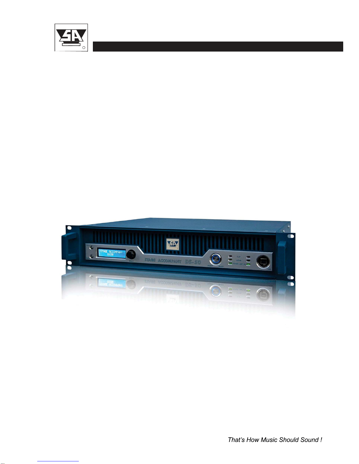
DS50 USER MANUAL
R
stage accompany
DIGITAL SERIES DS50
Digital PowerAmplifier
User Manual

DS50 USER MANUAL
R
stage accompany
Published by:
Stage Accompany
Training & Documentation
Haven28
2984 BR Ridderkerk, The Netherlands
Copyright © 2012 by Stage Accompany
All rights reserved. No part of this manual may be reproduced or transmitted in any form or by
any means, electronically or mechanical, without written permission from Stage Accompany,
except for the inclusion of brief quotations in a review.
First printing, May 2012
Printed in The Netherlands
Thismanualis intendedto provide
information
aboutthe StageAccompanyDS50. Everyeffort
has been made to make this manual complete and as accurate as possible. However no
warranty of suitability, purpose, or fitness is implied. The information is provided on an “as-is”
basis. Stage Accompany shall have neither liability nor responsibility to any person or identity
with respect to any loss or damages in connection with or arising from the information
contained in this manual.
Stage Accompany reserves the right to alter specifications without prior notice.

DS50 USER MANUAL
R
stage accompany
Table of
Contents
Quick Introduction to the
DS50
Introduction
Connections
Operation
Stage
Control
Recommendations
Technical Specifications
Warranty
Overview

DS50 USER MANUAL
R
stage accompany
TABLE OF CONTENTS
Table Of Contents
1
Quick
Introduction
to
the
DS50
.
.
.
.
.
.
.
.
.
.
.
.
.
.
.
.
.
.
.
.
.
.
.
.
.
.
.
.
.
.
.
.
.
1-1
2
Introduction
.
.
.
.
.
.
.
.
.
.
.
.
.
.
.
.
.
.
.
.
.
.
.
.
.
.
.
.
.
.
.
.
.
.
.
.
.
.
.
.
.
.
.
.
.
.
.
.
.
2-1
3
Connection
of
the
DS50
.
.
.
.
.
.
.
.
.
.
.
.
.
.
.
.
.
.
.
.
.
.
.
.
.
.
.
.
.
.
.
.
.
.
.
.
.
.
.
3-1
3.1
Mains
Power
Connection
.
.
.
.
.
.
.
.
.
.
.
.
.
.
.
.
.
.
.
.
.
.
.
.
.
.
.
.
.
.
.
.
.
.
.
3-1
3.2
Audio
Connections
.
.
.
.
.
.
.
.
.
.
.
.
.
.
.
.
.
.
.
.
.
.
.
.
.
.
.
.
.
.
.
.
.
.
.
.
.
.
.
.
3-4
3.3
Loudspeaker
Connections
.
.
.
.
.
.
.
.
.
.
.
.
.
.
.
.
.
.
.
.
.
.
.
.
.
.
.
.
.
.
.
.
.
.
3-5
4
Operation
.
.
.
.
.
.
.
.
.
.
.
.
.
.
.
.
.
.
.
.
.
.
.
.
.
.
.
.
.
.
.
.
.
.
.
.
.
.
.
.
.
.
.
.
.
.
.
.
.
.
.
4-1
4.1
System
check
.
.
.
.
.
.
.
.
.
.
.
.
.
.
.
.
.
.
.
.
.
.
.
.
.
.
.
.
.
.
.
.
.
.
.
.
.
.
.
.
.
.
.
.
4-1
4.2
Input
Setup
.
.
.
.
.
.
.
.
.
.
.
.
.
.
.
.
.
.
.
.
.
.
.
.
.
.
.
.
.
.
.
.
.
.
.
.
.
.
.
.
.
.
.
.
.
.
4-1
4.2.1
Gain
.
.
.
.
.
.
.
.
.
.
.
.
.
.
.
.
.
.
.
.
.
.
.
.
.
.
.
.
.
.
.
.
.
.
.
.
.
.
.
.
.
.
.
.
.
.
.
.
4-2
4.2.2
Input
Selection
.
.
.
.
.
.
.
.
.
.
.
.
.
.
.
.
.
.
.
.
.
.
.
.
.
.
.
.
.
.
.
.
.
.
.
.
.
.
.
.
4-2
4.2.3
Delay
.
.
.
.
.
.
.
.
.
.
.
.
.
.
.
.
.
.
.
.
.
.
.
.
.
.
.
.
.
.
.
.
.
.
.
.
.
.
.
.
.
.
.
.
.
.
.
4-2
4.2.4
Low
Pass
Filter.
.
.
.
.
.
.
.
.
.
.
.
.
.
.
.
.
.
.
.
.
.
.
.
.
.
.
.
.
.
.
.
.
.
.
.
.
.
.
.
4-2
4.2.5
High
Pass
Filter
.
.
.
.
.
.
.
.
.
.
.
.
.
.
.
.
.
.
.
.
.
.
.
.
.
.
.
.
.
.
.
.
.
.
.
.
.
.
.
4-3
4.2.6
Parametric
Equalizer
(PEQ).
.
.
.
.
.
.
.
.
.
.
.
.
.
.
.
.
.
.
.
.
.
.
.
.
.
.
.
.
.
4-3
4.2.7
Compressor
.
.
.
.
.
.
.
.
.
.
.
.
.
.
.
.
.
.
.
.
.
.
.
.
.
.
.
.
.
.
.
.
.
.
.
.
.
.
.
.
.
.
4-4
4.2.8
Limiter
.
.
.
.
.
.
.
.
.
.
.
.
.
.
.
.
.
.
.
.
.
.
.
.
.
.
.
.
.
.
.
.
.
.
.
.
.
.
.
.
.
.
.
.
.
.
4-4
4.2.9
Channel
Link
.
.
.
.
.
.
.
.
.
.
.
.
.
.
.
.
.
.
.
.
.
.
.
.
.
.
.
.
.
.
.
.
.
.
.
.
.
.
.
.
.
4-4
4.3
Output
Setup
.
.
.
.
.
.
.
.
.
.
.
.
.
.
.
.
.
.
.
.
.
.
.
.
.
.
.
.
.
.
.
.
.
.
.
.
.
.
.
.
.
.
.
.
4-5
4.3.1
Gain
.
.
.
.
.
.
.
.
.
.
.
.
.
.
.
.
.
.
.
.
.
.
.
.
.
.
.
.
.
.
.
.
.
.
.
.
.
.
.
.
.
.
.
.
.
.
.
.
4-5
4.3.2
Delay
.
.
.
.
.
.
.
.
.
.
.
.
.
.
.
.
.
.
.
.
.
.
.
.
.
.
.
.
.
.
.
.
.
.
.
.
.
.
.
.
.
.
.
.
.
.
.
4-5
4.3.3
Low
Pass
Filter.
.
.
.
.
.
.
.
.
.
.
.
.
.
.
.
.
.
.
.
.
.
.
.
.
.
.
.
.
.
.
.
.
.
.
.
.
.
.
.
4-5
4.3.4
High
Pass
Filter
.
.
.
.
.
.
.
.
.
.
.
.
.
.
.
.
.
.
.
.
.
.
.
.
.
.
.
.
.
.
.
.
.
.
.
.
.
.
.
4-6
4.3.5
Parametric
Equalizer
(PEQ).
.
.
.
.
.
.
.
.
.
.
.
.
.
.
.
.
.
.
.
.
.
.
.
.
.
.
.
.
.
4-6
4.3.6
Compressor
.
.
.
.
.
.
.
.
.
.
.
.
.
.
.
.
.
.
.
.
.
.
.
.
.
.
.
.
.
.
.
.
.
.
.
.
.
.
.
.
.
.
4-7
4.3.7
Limiter
.
.
.
.
.
.
.
.
.
.
.
.
.
.
.
.
.
.
.
.
.
.
.
.
.
.
.
.
.
.
.
.
.
.
.
.
.
.
.
.
.
.
.
.
.
.
4-7
4.3.8
Phase
Inverse.
.
.
.
.
.
.
.
.
.
.
.
.
.
.
.
.
.
.
.
.
.
.
.
.
.
.
.
.
.
.
.
.
.
.
.
.
.
.
.
.
4-7
4.3.9
Channel
Link
.
.
.
.
.
.
.
.
.
.
.
.
.
.
.
.
.
.
.
.
.
.
.
.
.
.
.
.
.
.
.
.
.
.
.
.
.
.
.
.
.
4-8

DS50 USER MANUAL
R
stage accompany
TABLE OF CONTENTS
4.4 System Menu . . . . . . . . . . . . . . . . . . . . . . . . . . . . . . . . . . . . . . . . . . . . 4-8
4.4.1
4.4.2
4.4.3
Load Preset . . . . . . . . . . . . . . . . . . . . . . . . . . . . . . . . . . . . . . . . . . 4-8
Save Preset . . . . . . . . . . . . . . . . . . . . . . . . . . . . . . . . . . . . . . . . . . 4-8
Access Level . . . . . . . . . . . . . . . . . . . . . . . . . . . . . . . . . . . . . . . . . 4-9
4.4.4 Version information . . . . . . . . . . . . . . . . . . . . . . . . . . . . . . . . . . . . 4-9
4.5 Indicators . . . . . . . . . . . . . . . . . . . . . . . . . . . . . . . . . . . . . . . . . . . . 4-8
5 StageControl . . . . . . . . . . . . . . . . . . . . . . . . . . . . . . . . . . . . . . . . . . . . . . . . 5-1
6 Recommendationsfor Optimum Use. . . . . . . . . . . . . . . . . . . . . . . . . . . . . 6-1
7 Technical
Specifications
. . . . . . . . . . . . . . . . . . . . . . . . . . . . . . . . . . . . . . . 7-1
8 Warranty . . . . . . . . . . . . . . . . . . . . . . . . . . . . . . . . . . . . . . . . . . . . . . . . . . . . 8-1
9
Overview
. . . . . . . . . . . . . . . . . . . . . . . . . . . . . . . . . . . . . . . . . . . . . . . . . . . . 9-1

1 -
1
DS50 USER MANUAL
R
stage accompany
QUICK INTRODUCTION
1 Quick Introduction to the DS50
Thank you for choosing a Stage Accompany Power Amplifier. Making this choice has guaran-
teed you many years of troublefree amplification.
If you have to start
usin
g theDS50 straight
away
and do not
have
thetimetoreadthe complete
manual, make sure that you at least read the following:
• Ensure that you have a reliable, well earthed power source. The required current for
the DS50 can be found in the table in paragraph 3.1.
• Connect the DS50 to your signal sources via the <INPUT> connectors. Connect this
amplifier to other units via the <LINK> outputs using short signal leads. Connect your
singlesignal
source
to the
channel
1 inputif you use the DS50 in
dedicated active
presets.
• Never make connections to the amplifier or to any preceding equipment with the ampli-
fier switched on!
•
Switch
theDS50 on
using
the
<POWER ON/OFF>
switch.
• Select the desired preset and input sensitivity by means of the <SELECT ROTATOR >.
Important
• For full-range operation at a 4 ohms load or higher please select preset 1 <2500 2500>
For full-range operation at a load below 4 ohms please preset 2 <2000 2000>
The DS50 is now ready for use.

2 -
1
DS50 USER MANUAL
R
stage accompany
INTRODUCTION
2 Introduction
The Stage Accompany DS50 is a dual channel, digital power amplifier and comprimises the
following
components:
• Balanced input stages.
• Two digital amplifiers wich deliver each 1600W into 8 ohms, 2500W into 4 ohms
and
2000W into 2 ohms.
• 64-bit 96kHz high quality DSP controller
• Advanced protection circuits.
The audio inputs and link outputs are connected internally without electronics. This is done to
prevent any loss of sound quality.With an input
impedance
of 25 kohms, it is posible to connect
a maximum of 30 DS50 amplifiers to a 600 ohms source like a mixing console. If more than
30 units need to be connected to a single source, a seperate signal driver must be
used.
The DS50 is
protected
against the
connection
of
speaker impedances
less than 2 ohms or even
short circuiting of the output. In this fault condition the power supply lines to the
amplifier
module will be interrupted.
The DS50 has a number of features, including:
• DSP processing.
• Two channel AES/EBU input.
• Dual auto-negotiation RJ45 ports.
• Switched mode power supply.
•Soft start to reduce power on inrush current.
•Class D operation.
•DDC (Dynamic Damping Control).
• Variable speed DC fan.
•Temperature, DC, HF and short circuit protection.

2-2
DS50 USER MANUAL
R
stage accompany
INTRODUCTION
DSP processing
The built in DSP module is a high quality four input, two output DSP processor with all
the
neccessary features for a professional amplifier. The unit features two analogue and one two
channel AES/EBU inputs with full configuration and real-time monitoring via PC controlled by
Ethernet and USB interface.
Two channel AES/EBU input
Two XLR-3 AES/EBU connectors
for
input and buffered output
are
mounted
attherear.
Dual auto-negotiation RJ45 ports
An internal high performance 10/100Mbps Ethernet switch module provides a simple network
connection
to your
workgroup
or a server.
Switched mode power supply
The amplifier stages are individual powered by a low weight high efficiency high power audio
SMPS, optimized from
the first
phase
of
design
to final
impletation
to
realize
the lowEMIsignature
requiredof the most demandingaudio applications.
Soft Start
The soft start circuit is active when the DS50 is turned on. The mains inrush current,
which
normally is in excess of 100 A is limited to a safe value. However, take care not to switch on
too many DS50 amplifiers at the same time, or you risk that the main fuses of your distribution
may trip.
Class D operation
The high performance class D output stages features a flat frequency response irrespective
of load
impedance, nearly frequency-independent distortion behaviour
and very low
radiated
and
conductedEMI.
DDC
DDC (Dynamic Damping Control) is a special way of measuring the cone movement of a
loudspeaker. The voltage induced in the voice coil is sensed and fed back to the amplifier’s
feedback circuit.
Hence, a
virtually infinite damping
is
achieved, which results
in
an
exceptionally
tight sound production.
DC fan
The built in DC fan has a continuous variable speed. Its control circuit monitors the temperature
of
the
output
devices and
the
temperature
of
the
power
supply.
The
speed
of the
fanis
calculated
out of this information. This system ensures that the fan always runs at optimum speed and
thus produces less noise.
Temperature, DC, HF and Short Circuit Protection
The amplifier and the loudspeakers are protected against all possible damages.

3-1
DS50 USER MANUAL
R
stage accompany
CONNECTIONS
OK
3 Connections
Only three connections need to be made: mains power, audio input signals, and loudspeaker
leads. Do not make any connections to the amplifier or to any preceding equipment with the
amplifier switched on!
3.1 Mains Power Connection
The DS50 is internally selectable for 110-120/220-240V 50/60Hz mains voltage. The mains
voltage is
configured
at the factory
according
to
standard
used in the country of
destination.
The
exact voltages are stated at the rear of the amplifier. Switching between mains voltages has to
done by an authorised Stage Accompany service centre. Connecting to the wrong voltage is
dangerous and may damage the amplifier. Always ensure that you use a correctly grounded
power supply. If more than one DS50 is to be used, it is advisable to connect each
one
separately to the nearest mains supply in stead of connecting several DS50s using an adapter
block (see figure 3-1).
DS50
DS50
DS50
DS50
DS50
DS50
Mains
Supply
Mains
Supply
Figure 3-1 DS50 connections to the mains supply.

3-2
DS50 USER MANUAL
R
stage accompany
CONNECTIONS
This will prevent unnecessary power loss in the mains cables. If circumstances do not allow
this, it is advisable to connect the adapter block directly to the power supply using a short cable
and then connect the individual DS50s to it using longer leads. Although this method is
not
ideal, it does limit power loss as much as possible.
Ultimately, it is possible to place the adapter block near the DS50s, but if a great deal of power
is required from the unit, the final current provided is far from optimum: loss of current leads to
unrecoverable loss of output power and therefore sound pressure.
Warning :
Always disconnect the DS50 from the power supply before operating on the fuse
holders!
Replace a blown fuse only with a new one of the same type and value!
Current Table
Below, the current consumption of the DS50 is tabulated for two selectable mains voltages.
The
power consumption shown applies
1/8 of
maximum output power
pink noise in 2
ohms,
wich
is representative for typical music program with occasional clipping. If your speaker system has
an impedance of 4 or 8 ohms you may multiply the currents by 0.5 or 0.25.
No. DS50s
Mains Voltage
(V)
110-120
220-240
Current Consumption (A)
1
18
9
2
36
18
3
54
27
4
72
36
5
90
45
6
108
54
7
126
63
8
144
72
9
162
81
Table 3-1 Current consumption as a function of the mains voltage at 1/8 of maximum
output power with pink noise in 2 ohms.
The mains voltage may NOT deviate more than -20 % to +10 % of the nominal value. The
proportionalmains voltage cable loss maynot exceed 10 %. Thefollowing formulamay be used
to calculate the maximum mains cable length in meters for 220-240 V models:
3-3
DS50 USER MANUAL
R
stage accompany
CONNECTIONS
Maximum Length (ML)
=
G *
45
N
The two input variables are:
N - number of DS50s supplied through the cable
G - cable gauge in square millimeters
For 110-120 V models the following formula applies:
Maximum Length (ML) = G * 11.25
N
This means that the cable length is proportional to the cable gauge, while it is inversely
proportional to the number of DS50s supplied through the cable.
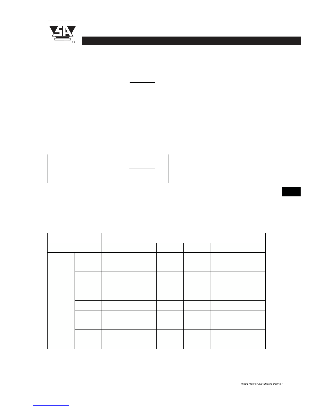
On this and the next page, per mains voltage a table is shown with the maximum mains cable
lenght
in
meters,
given the cable
gauge
in
square millimeters
and the
number
of
DS50s
supplied
through the cable.
110-120 V
Cable Gauge
(mm
2
)
1.5
2.5
4.0
6.0
10.0
16.0
No.
of
DS50s
1
17
27
45
67
112
180
2
9
14
22
34
57
90
3
6
9
15
22
3
7
60
4
4
7
12
1
7
28
45
5
3
6
9
13
22
36
6
3
4
7
12
19
30
7
3
4
6
9
16
25
8
2
3
6
7
13
20
9
2
3
5
7
12
19
10
2
3
5
7
12
16
Table 3-2 Maximum cable length as a function of the cable gauge and the number of
DS50s supplied through the cable
3-4
DS50 USER MANUAL
R
stage accompany
CONNECTIONS
2
1
3
NEUTRIK
220-240 V
Cable Gauge
(mm
2
)
1.5
2.5
4.0
6.0
10.0
16.0
No.
of
DS50s
1
45
112
180
270
450
720
2
34
57
90
135
225
360
3
2
2
37
60
80
150
240
4
16
28
45
60
112
180
5
13
22
36
54
90
144
6
12
16
30
45
75
120
7
9
16
25
39
64
103
8
9
13
22
34
57
90
9
7
12
19
30
49
79
10
7
12
18
27
45
72
Table 3-3 Maximum cable length as a function of the cable gauge and the number of
DS50s supplied through the cable.
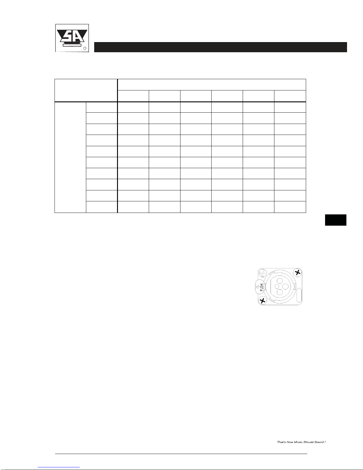
3.2 Audio Connections
The XLR connectors (analog audio,AES/EBU in and link) of the DS50 are wired as follows:
Pin 1 = shield
Pin 2 = normal phase (signal+ or “hot”)
Pin 3 = inverted phase (signal- or “cold”)
Always use high quality XLR connectors and shielded signal cables. Using the signal link
connectors, up to 30 DS50s can be linked without a problem. If more than 30 DS50s need to
be interconnected, a separate signal driver should be used.
Theinput
stages
are
electronically balanced.
To
make optimum use
of the
balanced input
stages
even in unbalanced situations, use balanced signal cables and connect pin 3 to pin 1 at the
output of the preceding equipment. If this is not possible, connect pin 3 to pin 1 at the input of
the DS50.
The digital input of the DS50 offers two input channels on one electronically balanced XLR-
connector
and will
accept AES/EBU
and S/PDIFinput signalsof 16 to 24 bit 44.1, 48, 88.2 or
96kHz.

3-5
DS50 USER MANUAL
R
stage accompany
CONNECTIONS
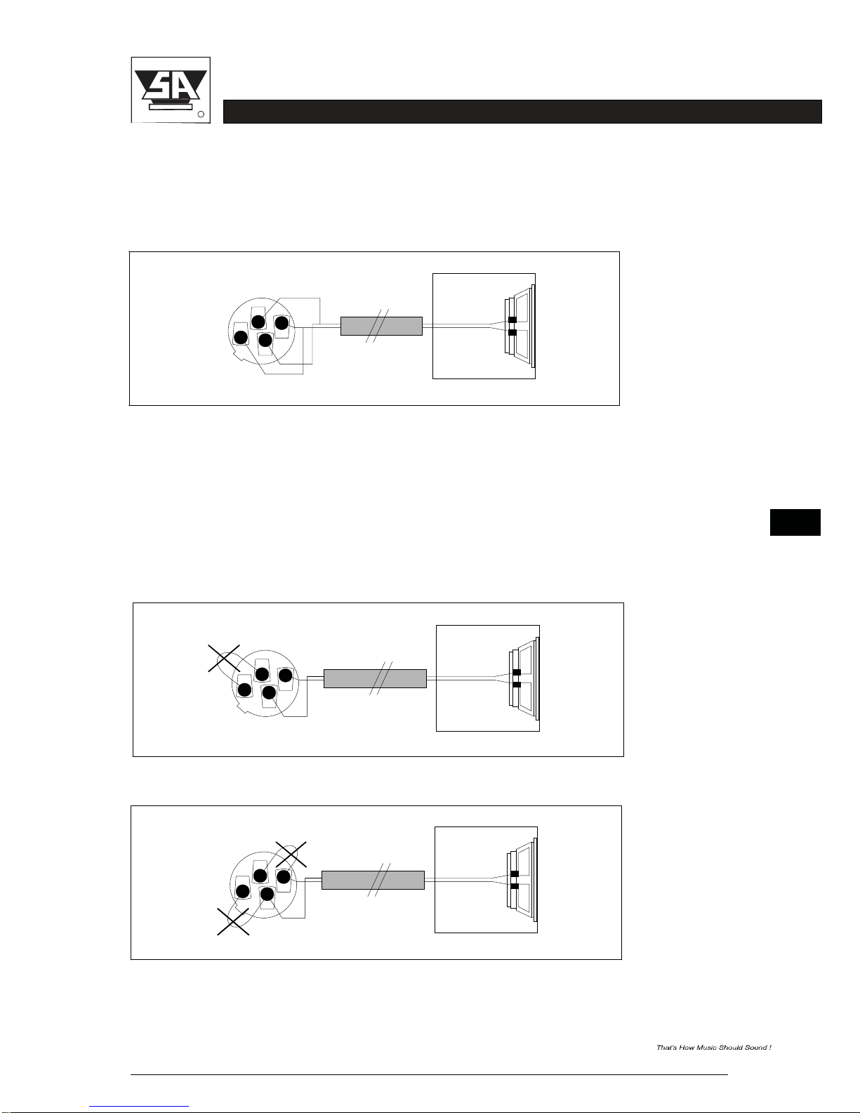
3.3 Loudspeaker Connections
Dueto theDDC
feature,
the DS50has 4
output terminals
per
channel instead
of 2. Thespeakon
connector is wired as follows:
1+
Pin 1+ = “hot” or Signal+
Pin 1- = “cold” or Signal-
Pin 2+ = “DDC hot” or DDC+
Pin 2- = “DDC cold” or DDC-
1-
2-
NEUTRIK
2+
For optimum performance, the amplifier to loudspeaker connectionsshould be made as shown
in figure 3-2.
The signal+ and DDC+ (Dynamic Damping Control) terminals are linked together at the
SPEAKON
NL4FC
2+
2-
1-
1+
Figure 3-2 DS50 4-terminal loudspeaker connection.
loudspeaker
+
terminal.
The
signal-
and DDC-
terminals
are
linked
at the
loudspeaker
- terminal.
A
maximum
damping is obtained with these
connections.
If your
speaker
system is not prepared
for a four terminal connection, link the DDC and the signal leads at the input of the enclosure
(see figure 3-3).
SPEAKON
NL4FC
2+
2-
1-
1+
Figure 3-3 DS50 2-terminal loudspeaker connection
3-6
DS50 USER MANUAL
R
stage accompany
CONNECTIONS
If you don’t want to use the DDC feature at all, the DDC and the signal leads should be linked
at the amplifier output in the speakon connector (see figure 3-4). The DDC terminals can also
be left unconnected but then the performance will be less.
SPEAKON
NL4FC
2+
2-
1-
1+
Figure 3-4 DS50 loudspeaker connection without DDC
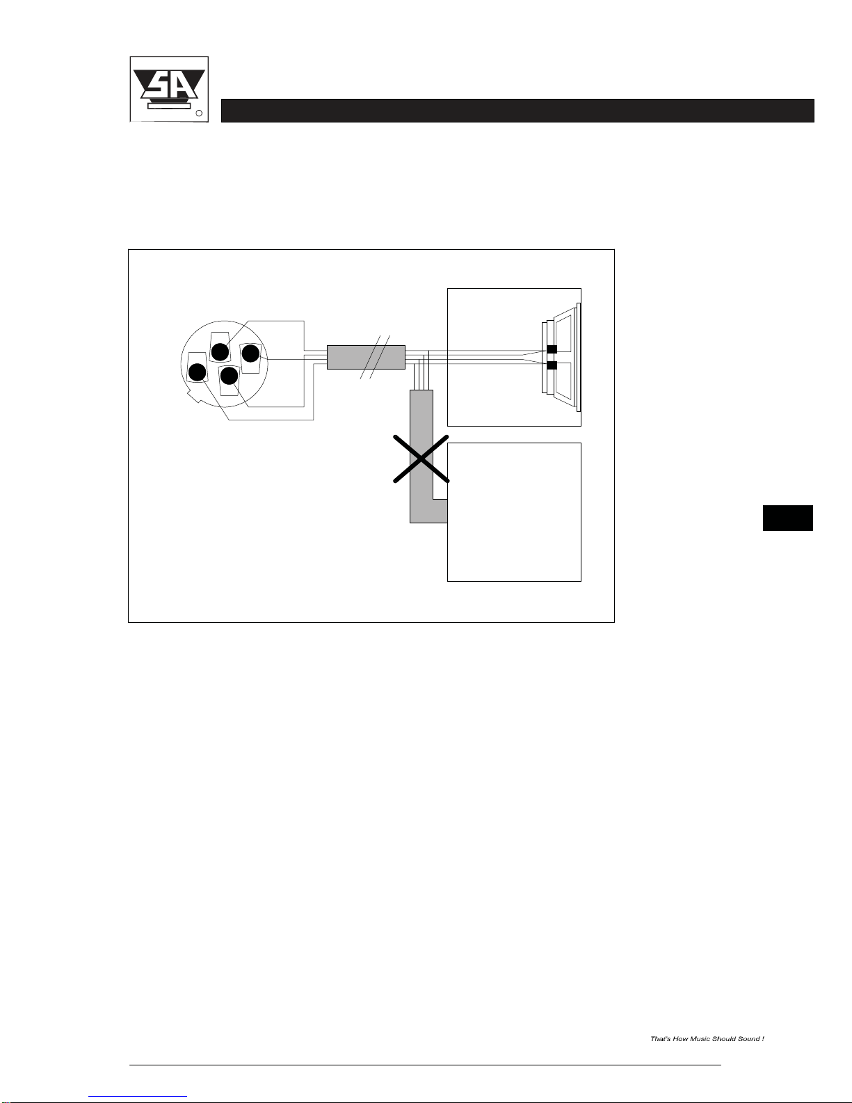
Warning ! Never short-circuit the DDC
terminals,
and never connect the signal+output terminal
to the DDC- terminal or vice versa (see figure 3-5). Since you are disabling the amplifier’s
feedback network, signal gain will be almost infinite. The smallest input signal will result in full
power output with the possibility of square waves damaging your loudspeakers!
Therefore, check your cables regularly. we also advice you to use special 4-wire loudspeaker
cable: 2 x 3.0 mm2 and 2 x 0.75 mm2 .
SPEAKON
NL4FC
2+
2-
1-
1+
Figure 3-5 Dangerous DS50 output connection
SPEAKON
NL4FC
2+
2-
1-
1+
Figure 3-6 Dangerous DS50 output connection
3-7
DS50 USER MANUAL
R
stage accompany
CONNECTIONS
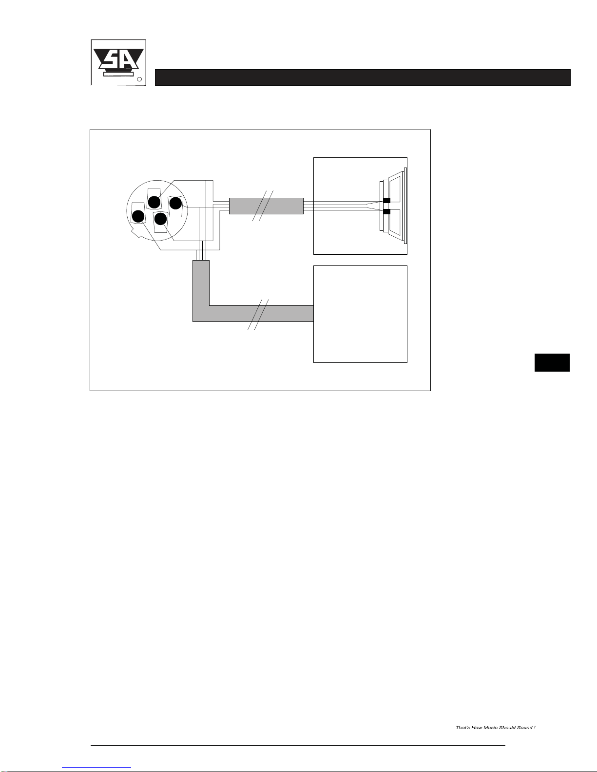
Whenmorespeakersaregoingtobeconnectedtooneamplifier,splittheoutputand DDCleads
as soon as possible behind the output terminals of the DS50 (see figure 3-7 on this and figure
3-8 on the next page).
SPEAKON NL4FC
2+
2-
-
1-
1+
Figure 3-7 Try to avoid this way of connecting several enclosures to the
DS50.
3-8
DS50 USER MANUAL
R
stage accompany
CONNECTIONS
SPEAKON NL4FC
2+
2-
-
1-
1+ OK
Figure 3-8 Correct way of connecting several enclosures to the DS50
The amplifier can cope with any load of 2 ohms or higher. This means that you may connect a
maximum of two 4 ohms, four 8 ohms or eight 16 ohms loudspeakers per channel in parallel.
Linking the loudspeakersfrom one enclosure to another has two major disadvantages:
1.The loudspeaker cable from the amplifier to the first enclosure conducts the current for all
enclosures, which means extra losses.
2.The DDC only works for the first enclosure.
Splitting the leads at the amplifier output terminals solves these problems (see figure 3-8). The
DDC system corrects the performance loss due to connectors, loudspeaker cables and so on.
However, it cannot prevent loss of power. So only use cables of minimal 2 x 1.5 mm2 or more
for the loudspeaker leads and 2 x 0.75 mm2 for the DDC leads.

3-9
DS50 USER MANUAL
R
stage accompany
CONNECTIONS
An indication of the proportional cable power loss (percentage of the amplifier’s total output
power) can be calculated using the following formula:
Proportional Power Loss =
100
29.4 * G *
R
1
+
L
where the variables represent:
L - cable length in meters
G - cable gauge in square millimeters
R - DC resistance of the loudspeaker(s) in ohms
This formula is based on the DC resistance in stead of the complex impedance of the
loudspeaker(s). However, the approximation can be used to get a good impression of the
loudspeaker cable power loss. Per loudspeaker impedance a table is shown in tables 3-4 to
3-7 with the proportional power loss, given the loudspeaker cable gauge in square millimeters
and the cable length in meters.
16
Ω
Cable Gauge
(mm
2
)
1.5
2.5
3.0
4.0
6.0
10.0
16.0
Cable
Length
(m)
10
1.4
0.8
0.7
0.5
0.4
0.2
0.1
20
2.8
1.7
1.4
1.1
0.7
0.4
0.3
30
4.1
2.5
2.1
1.6
1.1
0.6
0.4
40
5.4
3.3
2.8
2.1
1.4
0.8
0.5
50
6.6
4.1
3.4
2.6
1.7
1.1
0.7
100
12.4
7.8
6.6
5.0
3.4
2.1
1.3
Table 3-4 Proportional power loss as a function of loudspeaker cable gauge and cable
length (%).
3-10
DS50 USER MANUAL
R
stage accompany
CONNECTIONS
8
Ω
Cable Gauge
(mm
2
)
1.5
2.5
3.0
4.0
6.0
10.0
16.0
Cable
Length
(m)
10
2.8
1.7
1.4
1.1
0.7
0.4
0.3
20
5.4
3.3
2.8
2.1
1.4
0.8
0.5
30
7.8
4.9
4.1
3.1
2.1
1.3
0.8
40
10.2
6.4
5.4
4.1
2.8
1.7
1.1
50
12.4
7.8
6.6
5.0
3.4
2.1
1.3
100
22.1
14.5
12.4
9.6
6.6
4.1
2.6
Table 3-5 Proportional power loss as a function of loudspeaker cable gauge and cable
length (%).
4
Ω
Cable Gauge
(mm
2
)
1.5
2.5
3.0
4.0
6.0
10.0
16.0
Cable
Length
(m)
10
5.4
3.3
2.8
2.1
1.4
0.8
0.5
20
10.2
6.4
5.4
4.1
2.8
1.7
1.1
30
14.5
9.3
7.8
6.0
4.1
2.5
1.6
40
18.5
12.0
10.2
7.8
5.4
3.3
2.1
50
22.1
14.5
12.4
9.6
6.6
4.1
2.6
100
36.2
25.4
22.1
17.5
12.4
7.8
5.0
Table 3-6 Proportional power loss as a function of loudspeaker cable gauge and cable
length (%).
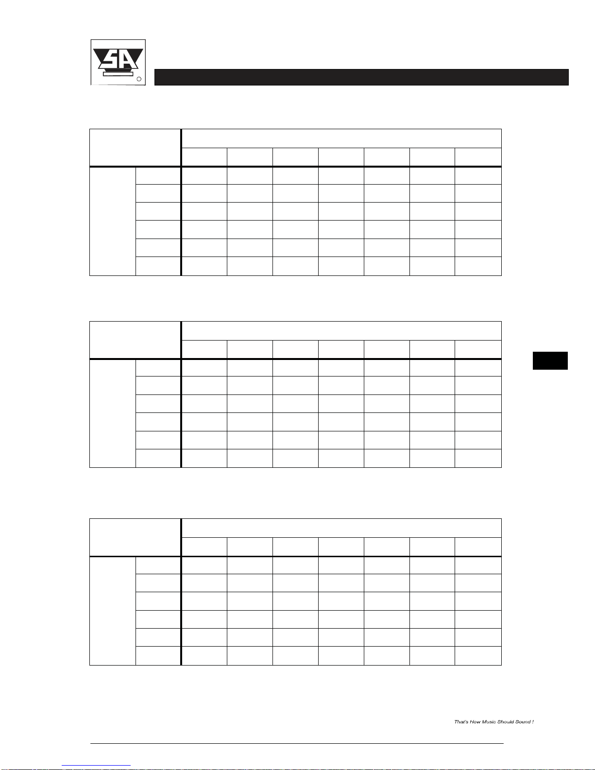
2
Ω
Cable Gauge
(mm
2
)
1.5
2.5
3.0
4.0
6.0
10.0
16.0
Cable
Length
(m)
10
10.2
6.4
5.4
4.1
2.8
1.7
1.1
20
18.5
12.0
10.2
7.8
5.4
3.3
2.1
30
25.4
16.4
14.5
11.3
7.8
4.9
3.1
40
31.2
21.4
18.5
14.5
10.2
6.4
4.1
50
36.2
25.4
22.1
17.5
12.4
7.8
5.0
100
53.1
40.5
36.2
29.8
22.1
14.5
9.6
Table 3-7 Proportional power loss as a function of loudspeaker cable gauge and cable
length (%).

4-1
DS50 USER MANUAL
R
stage accompany
OPERATION
4 Operation
The DSP (loudspeaker management) part of the DS50 offers a wide range of tools for sound
system design
and
setup. These
tools can make your
system
more
efficient
and
better
sounding,
but to get the best possible sound it is important to use these tools properly. The
following
section explains the various functions of the DS50.
Please note that if your DS50 amplifier is incorrectlly setup you will not be using your
system to its fullest potential and could be harming your speakers.
Always select the right Stage Accompany preset for your SA-system! (see 4.4)
We encourageyou to configure the device via PC or MAC programfor maximumease.
Working from the device is possible though.
4.1 System check
Before plugging the DS50 in, always make sure that the power supply matches the product
specification voltage. Install this device on a flat, stable surface, not bend or curved.
Do not supply power before all components of the system are set up and connected properly.
After
connection
to the correctmains voltage,the DS50can be
switched
on usingthe <POWER
ON/OFF> switch.
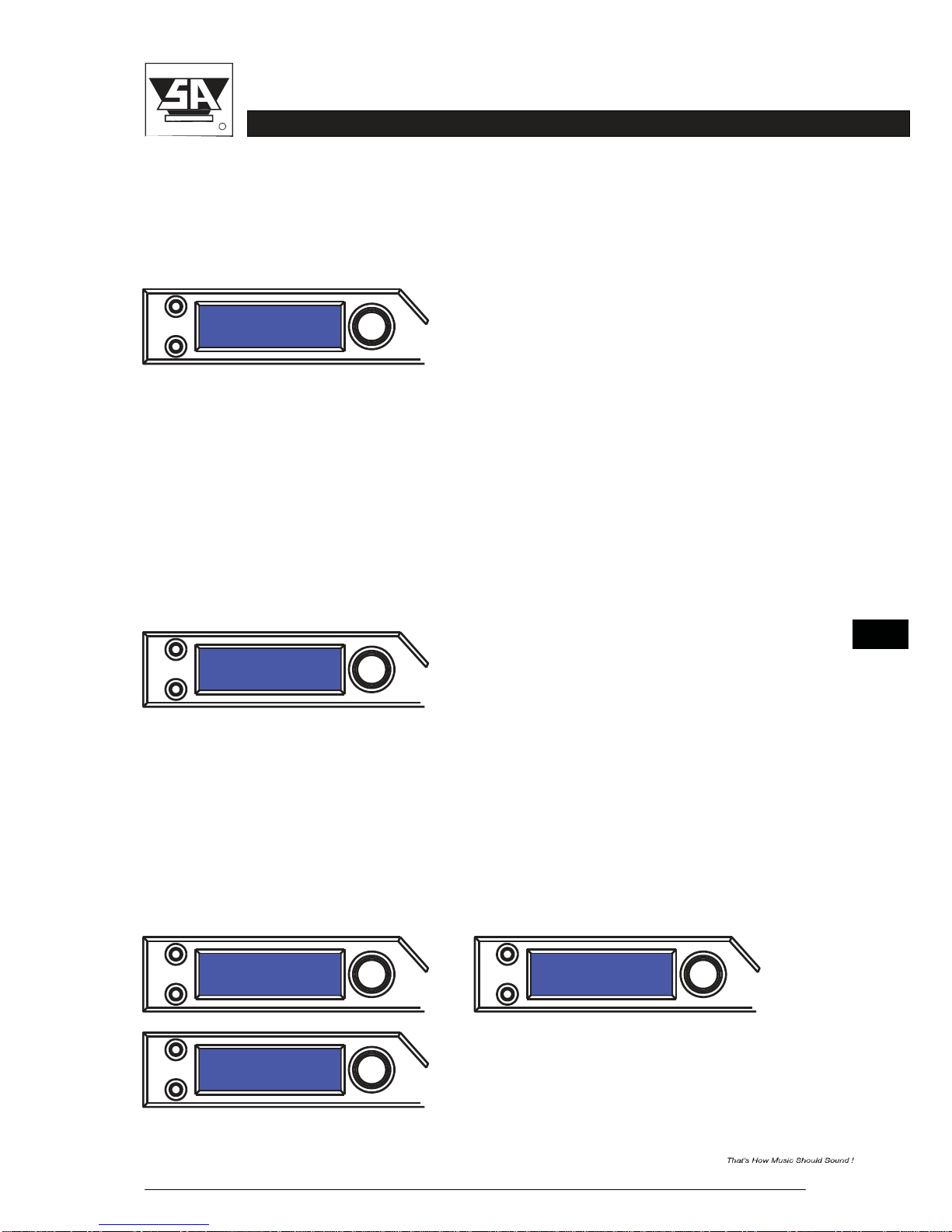
After a start-up period of a few seconds the LCD display will show the last used preset.
MENU
SA
DS50
2500 2500
EXIT
SELECT
4.2 Input setup
To enable
operation
of the control panel you first need to unlock the DS50. To
unlock
or lock the DS50 please refer to
chapter
4.4.3 (page
4-9).
Press the MENU button to load the dedicated preset of the currently used
loudspeaker
system. Rotate the encoder (SELECT button) to search for the desired preset and push the
encoder to select.Load preset by rotating the encoder to YES and pushing the encoder.
Nowthe right presethas beenloadedyou are free to make your own settings.
You are free to
save
your
presets
at
preset number
7 or
higher, preset
nr. 1
trough
6 are reserved
for factorysettings.
Press the SELECT button to select the input channel you wish to edit. To toggle through the
different items, press the SELECT button and rotate the encoder.
MENU MENU
Load: 1 LoadPreset ?
2500 2500 NO/yes
EXIT
SELECT
EXIT
SELECT
4-2
DS50 USER MANUAL
R
stage accompany
OPERATION
4.2.1 Gain
Adjust the gain by dialing the rotary
encoder.
The gain is
adjusted
in steps of
0.25dB.
Smaller
steps
(0.01dB)
can be set via the PC or MAC
interface.
MENU
In 1 Gain
0dB
EXIT
SELECT
4.2.2 Input Selection
The DS50 inputs are fixed. Input 1 is routed from the analog
XLR-input
of
channel 1,
channel 2 is routed from the analog XLR-input of channel 2, channel 3 and 4 are
routed
from the digital
AES/EBU XLR-input
on the
backside
of the
DS50.
4.2.3 Delay
Set the delay time by turning the encoder. The delay time on the front will be shown in ms, by
controlling the DS50 with StageControl the displayed unit can be changed between ms or s,
mm or m, feet, inches, or mils.
MENU
In 1 Delay
1.020ms
EXIT
SELECT
4.2.4 Low Pass Filter
Adjust the Low Pass Filter frequency by turning the rotary encoder. You can switch the
low
pass filter off by turning the rotary encoder up (clockwise) until the frequency passes 20kHz.
Press the rotary encoder to change the filter type. Selct the type by turning the rotary encoder.
You can choose from: Butterworth 6dB, Bessel 6dB, Butterworth 12dB, Bessel 12dB, Linkwitz
Riley 12dB, Butterworth 18dB, Bessel 18dB, Butterworth 24dB, Bessel 24dB. Higher
order
filters may be set by adding filter sections in the PEQ blocks (see below).
Enable or disable the Low Pass filter by rotating the encoder between on and off.
MENU
In 1 LowPass
Freq:
14500Hz
MENU
In 1 LowPass
Type:
BUT
24dB
EXIT
SELECT
EXIT
SELECT
MENU
In 1 LowPass
Enabled:
On
EXIT
SELECT
Table of contents
Other Stage Accompany Amplifier manuals


