OPERATING INSTRUCTIONS SA SERIES AMPLIFIERS
SA SERIES MIXER AMPLIFIERS
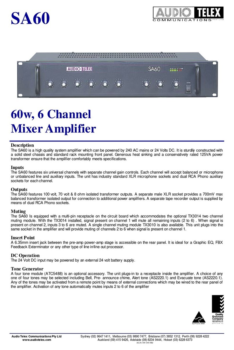
Congratulations on your purchase of our SA series mixer amplifier. As you are no doubt aware , mains
power must be disconnected before removing the lid or making any internal adjustments or connections to
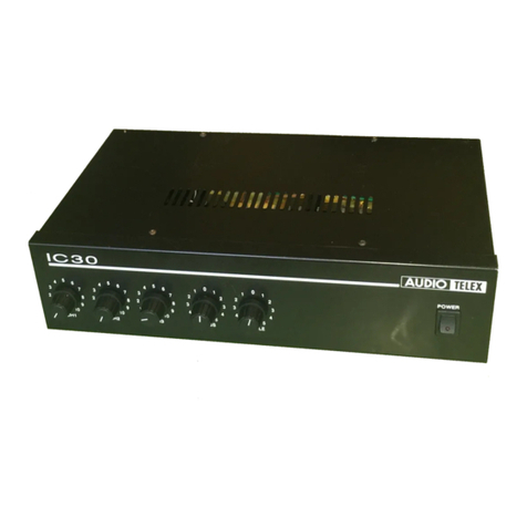
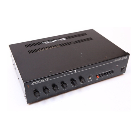
the amplifier. The SA Series Mixer Amplifiers are two rack height units suitable for direct rack mounting in a
standard 482mm rack format, or desV table mount by means of the rubber feet provided. They are equipped
with lour balanced microphone inputs, one line input and two auxiliary inputs (switched). The following
informa tion will provide setting up and connectior(iirformation for use in a conventional sound reintorcement
system. More detailed information and performance data is available from your dealer or any Audio Telex
Communication's oflice.
SETTING UP
For normal operation the master gain control should be set at mid position and the various microphone , line
or auxiliary cpntrols adjusted to their desired level. See details under " controls" below.
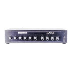
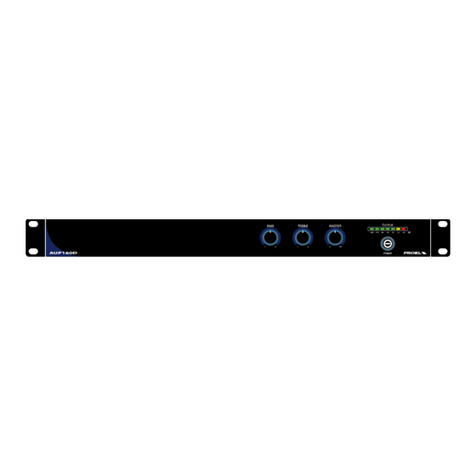
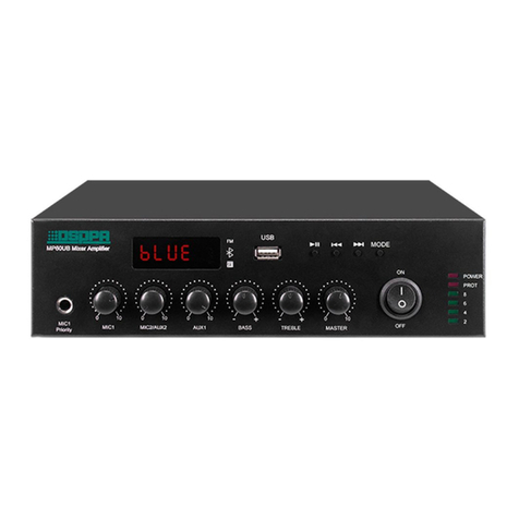
PANEL CONTROLS (fig 1 )
7...." MASTER " This control adjusts the overallvolume from the output of the mixer section of the amplifier.
Normal position for this control is 5 , which will enable the overall volume level from the amplifler to be
adjustecl up or down as required.
1...." MIC " Marked one to four, these controls will respond to microphone inputs connected at the rear of the
amplifier.The setting will depend upon the sensitivity of the microphone, which is connected. Generally a
setting of six to seven is ideal for most dynamic microphones with an impedance of 200 ohms, however the
purpose of multiple microphone inputs is to enable microphones o{ varying levels to be mixed to produce the
desired performance level.
2...." LINE " The line input will respond to inputs connected to the appropriate connections at the rear of the
amplilier.Generally, program sources sucfi as a tape deck, cd disc player, telephone line or wireless
microphone can be connected to this input.
3...." AUX " The auxiliary control is used in conjunction with the switch marked " AUX1 - AUX2 "(4). Auxiliary
inputs such as tape decks, background music players, radio tuners or wireless microphones are some of the
sources normally connected to these inputs. The switch " AUX1 - AUX2 " should be pressed " in " to connect
auxiliary input one and " out " to connect auxiliary input two. Note that it is not possible to amplify both
auxiliary inputs simultaneously , although they can be permanently connected , ( see connection details ) .
5...." BAS.S " The bass control will normally be operated in the zero position to obtain a flat overall
responsefor the amplifier. To boost the bass response ol the amplilier turn the control clockwise towards
five. To cut bass response turn the cantrol counter clockwise towards five.
6...." TREBLE " The treble control will normally be operated in the zero position , which sets the treble
response of the amplifier for a flat performance. To boost the high frequency perform ance of the amplilier ,
adjust the control cloclarvise towards five. To cut the high frequency response , turn the control counter
dockwise towards five.
9...." VU METER " Marked in decibel graduation from +3 to 21 , the light emitting diodes will indicate the
volume level at the output of the amplifier. For normal operation the l.e.d.s glow green as they modulate with
the output level of the amplifier. lf the lights cunsistently indicate red, the amplifier is being over-driven ,
resulting in distortion in the quality of the output signal.
8...." POWER " This switch turns on or off the mains power to the amplifier. An Le.d. glows red to indicate
the amplifier is turned on.
e- lT
'n t r -
I I r( lt ?(
9l
loroo
I tl vrcr Mr'
a,) -:_
io rlo rj-o
? 3 o ? tr o ,7
13 :l to r( l0
79 ,\ -/9 i'\ -,e
i' '"*:t t";lt
r_l)
