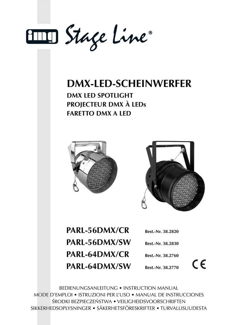
Stageline PARL-45SET User manual

ELECTRONICS FOR SPECIALISTS ELECTRONICS FOR SPECIALISTS ELECTRONICS FOR SPECIALISTS ELECTRONICS FOR SPECIALISTS
PARL-45SET Bestellnummer 38.6850
BEDIENUNGSANLEITUNG
INSTRUCTION MANUAL
MODE D’EMPLOI
ISTRUZIONI PER L’USO
GEBRUIKSAANWIJZING
MANUAL DE INSTRUCCIONES
INSTRUKCJA OBSŁUGI
SIKKERHEDSOPLYSNINGER
SÄKERHETSFÖRESKRIFTER
TURVALLISUUDESTA
DMX-LED-Scheinwerfer-Set
Set of DMX LED Spotlights

2
ELECTRONICS FOR SPECIALISTS ELECTRONICS FOR SPECIALISTS ELECTRONICS FOR SPECIALISTS ELECTRONICS FOR SPECIALISTS
D Deutsch . . . . . . . . . . . . . . . Seite 4
GB English . . . . . . . . . . . . . . . Page 10
F Français . . . . . . . . . . . . . . Page 16
I Italiano . . . . . . . . . . . . . . . Pagina 22
NL Nederlands . . . . . . . . . . . . Pagina 28
E Español . . . . . . . . . . . . . . . Página 34
PL Polski . . . . . . . . . . . . . . . . Strona 40
DK Dansk . . . . . . . . . . . . . . . . Sida 46
S Svenska . . . . . . . . . . . . . . . Sidan 46
FIN Suomi . . . . . . . . . . . . . . . . Sivulta 47

3

4
D
A
CH
DMX-LED-Scheinwerfer-Set
Bitte lesen Sie diese Anleitung vor dem Betrieb
gründlich durch und heben Sie sie für ein späteres
Nachlesen auf. Auf der ausklappbaren Seite 3 fin-
den Sie alle beschriebenen Bedienelemente und
Anschlüsse.
Inhalt
1 Übersicht der Bedienelemente und
Anschlüsse . . . . . . . . . . . . . . . . . . . . . . . . 4
2 Hinweise für den sicheren Gebrauch . . . 5
3 Einsatzmöglichkeiten . . . . . . . . . . . . . . . . 5
4 Inbetriebnahme . . . . . . . . . . . . . . . . . . . . . 5
4.1 Betrieb mit dem Stativ . . . . . . . . . . . . . . . . . 5
4.2 Festinstallation . . . . . . . . . . . . . . . . . . . . . . 6
4.3 Scheinwerfer ausrichten . . . . . . . . . . . . . . . 6
4.4 Stromversorgung . . . . . . . . . . . . . . . . . . . . . 6
5 Bedienung . . . . . . . . . . . . . . . . . . . . . . . . . 6
5.1 Eigenständiger Betrieb . . . . . . . . . . . . . . . . 6
5.1.1 Farbstrahler und Stroboskop . . . . . . . . . . 6
5.1.2 Farbwechsel- und Lauflichtprogramme . . 6
5.1.3 Musiksteuerung . . . . . . . . . . . . . . . . . . . . 7
5.1.4 Fußfernsteuerung . . . . . . . . . . . . . . . . . . 7
5.1.5 Master/Slave-Betrieb . . . . . . . . . . . . . . . 7
5.2 DMX-Steuerung . . . . . . . . . . . . . . . . . . . . . 7
5.2.1 Anschluss . . . . . . . . . . . . . . . . . . . . . . . . 8
5.2.2 Anzahl der DMX-Kanäle und
Startadresse einstellen . . . . . . . . . . . . . . 8
6 Technische Daten . . . . . . . . . . . . . . . . . . . 8
6.1 DMX-Funktionen im 15-Kanal-Betrieb . . . . 9
6.2 Menüstruktur . . . . . . . . . . . . . . . . . . . . . . . . 9
1 Übersicht der Bedienelemente
und Anschlüsse
1Montage- und Feststellschraube jeweils für
einen Scheinwerfer
Auf der Oberseite der Steuereinheit befinden
sich zusätzliche Gewindelöcher; bei Bedarf die
Schrauben herausdrehen und die Scheinwerfer
dort befestigen.
2Feststellschrauben für die vertikale Neigung
des Scheinwerfers
3Halterung für die Netzsicherung
Eine geschmolzene Sicherung nur durch eine
gleichen Typs ersetzen.
4Netzbuchse zum Anschluss an eine Steckdose
(230 V~/50 Hz) über das beiliegende Netzkabel
5Anschluss POWER OUT zur Stromversorgung
eines weiteren Gerätes
6Regler SENSITIVITY zum Einstellen der Mikro-
fonempfindlichkeit für musikgesteuerte Licht-
effekte
7Mikrofon für musikgesteuerte Lichteffekte
8XLR-Einbaustecker DMX IN: DMX-Signalein-
gang zum Anschluss eines Lichtsteuergerätes
oder an den DMX-Signalausgang eines ande-
ren DMX-gesteuerten Gerätes
9XLR-Buchse DMX OUT: DMX-Signalausgang
zum Anschluss an den DMX-Eingang eines wei-
teren DMX-gesteuerten Gerätes
10 Anschluss für die beiliegende Fernbedienung (13)
11 Display
12 Bedientasten
Taste MENU zur Wahl der Betriebsart
Tasten UP und DOWN zum Ändern einer Ein-
stellung
Taste ENTER zum Aufrufen der Einstellmöglich-
keiten und zum Speichern einer Einstellung
13 Fernbedienung mit zwei Fußtasten
Taste PROGRAMS zur Wahl eines der 12 auto-
matisch ablaufenden Lichtprogramme oder einer
der 7 Leuchtfarben
Taste BLACKOUT zum Aus- und Wiederein-
schalten des Lichtes

5
D
A
CH
2 Hinweise für den
sicheren Gebrauch
Das Gerät entspricht allen relevanten Richtlinien
der EU und ist deshalb mit gekennzeichnet.
Beachten Sie auch unbedingt folgende Punkte:
GVerwenden Sie das Gerät nur im Innenbereich
und schützen Sie es vor Tropf- und Spritzwasser,
hoher Luftfeuchtigkeit und Hitze (zulässiger Ein-
satztemperaturbereich 0 – 40 °C).
GStellen Sie keine mit Flüssigkeit gefüllten Ge-
fäße, z. B. Trinkgläser, auf das Gerät.
GNehmen Sie das Gerät nicht in Betrieb oder zie-
hen Sie sofort den Netzstecker aus der Steck-
dose,
1. wenn sichtbare Schäden am Gerät oder am
Netzkabel vorhanden sind,
2. wenn nach einem Sturz oder Ähnlichem der
Verdacht auf einen Defekt besteht,
3. wenn Funktionsstörungen auftreten.
Geben Sie das Gerät in jedem Fall zur Reparatur
in eine Fachwerkstatt.
GZiehen Sie den Netzstecker nie am Kabel aus
der Steckdose, fassen Sie immer am Stecker an.
GVerwenden Sie für die Reinigung nur ein trocke-
nes, weiches Tuch, niemals Wasser oder Chemi-
kalien.
GWird das Gerät zweckentfremdet, nicht sicher
montiert, nicht richtig angeschlossen, falsch
bedient oder nicht fachgerecht repariert, kann
keine Haftung für daraus resultierende Sach-
oder Personenschäden und keine Garantie für
das Gerät übernommen werden.
3 Einsatzmöglichkeiten
Das Scheinwerferset PARL-45SET besteht aus
vier flachen LED-Scheinwerfern, montiert an einer
Steuereinheit. Es dient zur Effektbeleuchtung, z. B.
auf Bühnen, in Diskotheken und Festsälen. In
jedem Scheinwerfer sind als Lichtquelle drei super-
helle RGB-LEDs eingesetzt. Mit den LEDs kann
farbiges Licht in den drei Grundfarben (Rot, Grün
und Blau) und deren Mischfarben abgestrahlt
werden.
Ein Set lässt sich allein, mit der beiliegenden
Fußfernbedienung oder an einem DMX-Lichtsteuer-
gerät (3 oder 15 DMX-Steuerkanäle) betreiben.
Zudem lassen sich mehrere Scheinwerfersets zu-
sammenschalten (Master/Slave-Betrieb) und ge-
meinsam über eine Fußfernbedienung steuern. Es
stehen verschiedene Lichtprogramme zur Verfü-
gung. Das integrierte Mikrofon sorgt dabei für
musiksynchrone Effekte.
Zum Lieferumfang gehören ein Stativ und zwei
Transporttaschen für den mobilen Betrieb sowie
zwei Montagewinkel für eine Festinstallation.
4 Inbetriebnahme
4.1 Betrieb mit dem Stativ
1) Das Stativ auf einen waagerechten, festen
Untergrund stellen. Für einen sicheren Stand
die Stativbeine maximal spreizen und mit der
Feststellschraube fixieren.
2) Die Steuereinheit mit den Scheinwerfern auf
das Stativrohr (a) setzen und mit einer der bei-
liegenden Schrauben (b) fixieren (Abb. 3).
3) Zum Einstellen der gewünschten Betriebshöhe
das Teleskoprohr herausziehen. Den Siche-
rungsstift durch die beiden Löcher für die
gewünschte Höhe stecken und das Rohr soweit
wieder hineinschieben, dass der Sicherungsstift
auf dem Außenrohr aufliegt. Das Teleskoprohr
zusätzlich mit der Feststellschraube fixieren.
WICHTIG!
GDas Stativ muss standsicher aufgestellt werden.
Das Teleskoprohr nur so hoch ausziehen, wie ein
sicherer Halt gewährleistet ist.
GVor dem Betrieb alle Feststellschrauben überprü-
fen und ggf. festziehen.
GAlle Anschlusskabel so verlegen, dass niemand
darüber stolpern kann und dadurch das Stativ
umfällt.
WARNUNG Das Gerät wird mit lebensgefährli-
cher Netzspannung versorgt. Neh-
men Sie deshalb niemals selbst Ein-
griffe am Gerät vor! Es besteht die
Gefahr eines elektrischen Schlages.
Soll das Gerät endgültig aus dem Betrieb
genommen werden, übergeben Sie es zur
umweltgerechten Entsorgung einem örtli-
chen Recyclingbetrieb.

6
D
A
CH
4.2 Festinstallation
Für eine Festinstallation an einer Wand oder Decke
die beiden Montagewinkel (c) fachgerecht an ge-
eigneter Stelle befestigen. Die Steuereinheit mit
den beiliegenden Griffschrauben (d) an den Win-
keln festschrauben (Abb. 4).
4.3 Scheinwerfer ausrichten
Zum Ausrichten der Scheinwerfer die jeweiligen
Feststellschrauben (1 und 2) lösen und den
Scheinwerfer in die gewünschte Richtung drehen
und neigen. Dabei darauf achten, dass die Kabel
nicht gedehnt oder gequetscht werden. Die Schrau-
ben anschließend wieder festdrehen.
Auf der Oberseite der Steuereinheit befinden
sich zusätzliche Gewindelöcher, um die Schein-
werfer auch dort montieren zu können. Dazu die
Schrauben (1) der Scheinwerfer herausdrehen und
die Scheinwerfer in gleicher Art mit den Schrauben
und Gummischeiben auf der Oberseite befestigen.
4.4 Stromversorgung
Das Scheinwerferset über die Netzbuchse (4) mit
dem beiliegenden Netzkabel an eine Steckdose
(230 V~/50 Hz) anschließen. Das Gerät ist damit
eingeschaltet. Das Display (11) zeigt den zuletzt
gewählten Betriebsmodus an und erlischt nach
30 s. Zur Betriebsanzeige leuchtet dann nur ein
Punkt. Sobald eine Bedientaste (12) gedrückt wird,
leuchtet das Display wieder für 30 s.
Werden mehrere PARL-45SET verwendet, kann
die Buchse POWER OUT (5) des ersten Gerätes
über ein Netzkabel mit einem Kaltgerätestecker und
einer Kaltgerätekupplung (z. B. AAC-170/SW aus
dem Sortiment von MONACOR) mit der Netz-
buchse (4) des zweiten Gerätes verbunden werden.
Das zweite Gerät kann dann wieder mit dem dritten
Gerät verbunden werden usw., bis alle Geräte in
einer Kette angeschlossen sind. Auf diese Weise
lassen sich maximal 20 Geräte zusammenschalten.
Die Buchse POWER OUT kann auch zur Strom-
versorgung anderer (Lichteffekt-) Geräte genutzt
werden. Jedoch dürfen die Buchsen POWER IN
und POWER OUT nicht mit einem Strom von mehr
als 6,3 A belastet werden. Es kann sonst durch die
Überlastung ein Kurzschluss und Brand verursacht
werden. Die Sicherung (3) sichert diese Buchsen
nicht ab.
5 Bedienung
Die Bedientasten MENU, UP, DOWN und ENTER
(12) dienen zum Auswählen des Betriebsmodus
und verschiedener Funktionen. Die Menüstruktur
auf der Seite 9 zeigt, wie die Modi und Funktionen
angewählt werden.
5.1 Eigenständiger Betrieb
5.1.1 Farbstrahler und Stroboskop
In diesem Modus strahlen die Scheinwerfer kon-
stant in einer einstellbaren Farbe. Zusätzlich lässt
sich die Stroboskop-Funktion einschalten.
1) Die Taste MENU so oft drücken, bis das Display
anzeigt.
2) Die Taste ENTER drücken. Das Display zeigt
für die Farbe Rot an und deren Helligkeitswert
zwischen 00 und 08.
3) Mit den Tasten UP und DOWN die gewünschte
Helligkeit für die Farbe Rot einstellen.
4) Durch mehrfaches Drücken der Taste ENTER
lassen sich nacheinander auch die Farben
Grün ( ), Blau ( ) und die Stroboskop-Funk-
tion ( ) anwählen. Danach beginnt der Anwähl-
zyklus wieder mit , usw. Für jede Farbe
die Helligkeit einstellen und ggf. auch die Stro-
boskopfrequenz ( = kein Stroboskop,
= langsam … = schnell).
Tipp: Beim Einstellen der Helligkeit der Farben Rot,
Grün und Blau ändert sich nicht nur deren Helligkeit, son-
dern bei einer Farbmischung auch der Farbton. Darum
zuerst die Farbe, die dominieren soll, auf die gewünschte
Helligkeit einstellen und danach die anderen beiden Far-
ben dazumischen. Soll die Farbmischung Weiß ergeben,
zuerst die Helligkeit der Farbe Grün einstellen, weil diese
dem Auge am hellsten erscheint. Dann mit Rot zu Gelb
mischen und zuletzt mit Blau zu Weiß mischen.
5) Zum Speichern der Einstellung die Taste ENTER
so oft drücken, bis das Display anzeigt.
5.1.2 Farbwechsel- und Lauflichtprogramme
Das Gerät verfügt über 12 automatisch ablaufende
Lichtprogramme mit einstellbarer Geschwindigkeit:
1) Die Taste MENU so oft drücken, bis das Display
und eine Zahl zwischen 01 und 12 anzeigt.
Die Zahl zeigt die Programmnummer an.
2) Mit den Tasten UP und DOWN ein Lichtpro-
gramm auswählen.
3) Um die Geschwindigkeit zu ändern, die Taste
ENTER so oft drücken, bis das Display und
eine Zahl zwischen 00 und 08 anzeigt. Mit den
Tasten UP und DOWN die Geschwindigkeit ein-
stellen. Bei der Einstellung ist das Schein-
werferlicht ausgeschaltet.
WARNUNG Blicken Sie nicht für längere Zeit
direkt in die Lichtquelle, das kann zu
Augenschäden führen.
Beachten Sie, dass sehr schnelle
Lichtwechsel bei fotosensiblen Men-
schen und Epileptikern epileptische
Anfälle auslösen können!
4) Zum Speichern der Einstellung die Taste ENTER
so oft drücken, bis das Display und die Pro-
grammnummer anzeigt.
5.1.3 Musiksteuerung
Die Scheinwerfer können durch das Mikrofon (7)
musikgesteuert werden. Dazu lassen sich vier ver-
schiedene Steuerprogramme auswählen:
1) Die Taste MENU so oft drücken, bis das Display
anzeigt.
2) Die Taste ENTER drücken: Der zuletzt einge-
stellte Musikmodus ist aktiviert und wird im Dis-
play angezeigt. Mit der Taste UP oder DOWN
aus den vier Modi den gewünschten auswählen:
= Farbwechsel Rot, Grün, Blau, Gelb,
Türkis, Violett, Weiß, Rot …
= Farbwechsel Rot, Grün, Blau, Rot …
= Lauflicht
= Aufleuchten nur in Weiß
3) Zum Speichern der Einstellung die Taste ENTER
drücken, sodass das Display anzeigt.
4) Den Regler SENSITIVITY (6) für die Empfind-
lichkeit des Mikrofons (7) so weit im Uhrzeiger-
sinn aufdrehen, bis die Scheinwerfer wie
gewünscht auf die Musik reagieren. Beim
Ändern der Lautstärke an der Musikanlage
muss auch die Mikrofonempfindlichkeit entspre-
chend angepasst werden. Sollte die Musik-
steuerung trotz weit aufgedrehten Empfindlich-
keitsreglers nicht optimal funktionieren, die
Lautstärke erhöhen oder den Abstand zwischen
Schallquelle und Mikrofon verringern.
5.1.4 Fußfernsteuerung
Über die mitgelieferte Fußfernbedienung (13) kön-
nen die 12 Lichtprogramme angewählt werden
sowie 7 verschiedene Leuchtfarben.
1) Den Stecker der Fernbedienung in die Buchse
(10) an der Steuereinheit stecken. Die Steck-
verbindung durch Festdrehen der Überwurfmut-
ter sichern.
2) Mit der Taste PROGRAMS werden zuerst nach-
einander die 7 verschiedenen Leuchtfarben in
maximaler Helligkeit angewählt. Das Display
zeigt dabei an.
3) Durch weiteres Drücken der Taste PROGRAMS
folgen nacheinander die 12 Lichtprogramme
(Anzeige … ). Danach wird ange-
zeigt und die Programme wechseln automa-
tisch. Durch erneutes Drücken beginnt der An-
wählzyklus wieder mit .
4) Mit der Taste BLACKOUT lässt sich das Licht
ausschalten (Anzeige ). Zum Wiederein-
schalten die Taste BLACKOUT erneut betätigen
oder mit der Taste PROGRAMS auf das nächste
Lichtprogramm schalten.
5.1.5 Master/Slave-Betrieb
Mehrere Geräte PARL-45SET können synchron
betrieben werden. Dabei übernimmt ein Gerät
(Master-Gerät) die Steuerung der übrigen Geräte
(Slave-Geräte). Die Geräte miteinander zu einer
Kette verbinden. Siehe dazu Kapitel 5.2.1, jedoch
ohne den Bedienschritt 1 zu beachten.
1) Alle Slave-Geräte auf Slave-Betrieb einstellen:
a) Die Taste MENU so oft drücken, bis das Dis-
play und eine Zahl zwischen 001 und 512
anzeigt.
b) Die Taste ENTER drücken, sodass rechts
neben dem ein Punkt aufleuchtet.
c) Mit der Taste UP oder DOWN die Zahl 001
einstellen.
d) Mit der Taste ENTER die Einstellung spei-
chern. Der Punkt erlischt. Wenn das Slave-
Gerät jedoch Steuersignale vom Master-
Gerät empfängt, blinkt der Punkt schnell.
2) Am Master-Gerät den gewünschte Betriebs-
modus einstellen (Kapitel 5.1.1 – 5.1.3).
3) Am Master-Gerät kann auch die Fußfernbedie-
nung angeschlossen werden (Kapitel 5.1.4),
um alle Slave-Geräte mit dem Master-Gerät
synchron zu steuern.
5.2 DMX-Steuerung
DMX ist die Abkürzung für Digital Multiplexund
ermöglicht die digitale Steuerung von mehreren
DMX-Geräten über eine gemeinsame Steuerlei-
tung. Zur Bedienung über ein DMX-Lichtsteuergerät
verfügt das Scheinwerferset über 15 DMX-Steuer-
kanäle. Es lässt sich bei Bedarf aber auch über nur
3 Kanäle steuern. Für den 15-Kanal-Betrieb sind die
Funktionen der Kanäle und die entsprechenden
DMX-Werte im Kapitel 6.1 angegeben.
Für den DMX-Betrieb des PARL-45SET sind fol-
gende Geräte von „img Stage Line“ geeignet:
Modell Anzahl der
DMX-Kanäle Bemerkung
DMX-1USB 510 Computer-Software
mit DMX-Konverter
DMX-510USB 510 Computer-Software
mit DMX-Konverter
DMX-3216 512 DMX-Steuerpult
DMX-4840 484 DMX-Steuerpult
LC-8DMX 8 ab Startkanal 368;
PARL-45SET im 3-Kanal-
Modus betreiben
LC-8LED 128 steuerbar im
„Record“-Modus
7
D
A
CH

5.2.1 Anschluss
Für die DMX-Verbindung sind 3-polige XLR-An-
schlüsse mit folgender Kontaktbelegung vorhan-
den:
Pin 1 = Masse, 2 = DMX
-
, 3 = DMX+
Zum Anschluss sollten spezielle Kabel für die DMX-
Signalübertragung verwendet werden (z. B. Kabel
der CDMXN-Serie von „img Stage Line“). Bei Lei-
tungslängen ab 150 m wird grundsätzlich das Zwi-
schenschalten eines DMX-Aufholverstärkers emp-
fohlen (z. B. SR-103DMX von „img Stage Line“).
1) Den Eingang DMX IN (8) mit dem DMX-Aus-
gang des Lichtsteuergerätes oder eines ande-
ren DMX-gesteuerten Gerätes verbinden.
Falls die Fußfernbedienung (13) angeschlos-
sen ist, diese von der Steuereinheit trennen,
damit sie die DMX-Steuerung nicht stört.
2) Den Ausgang DMX OUT (9) mit dem DMX-Ein-
gang des nächsten DMX-Gerätes verbinden.
Dessen Ausgang wieder mit dem Eingang des
nachfolgenden DMX-Gerätes verbinden usw.,
bis alle DMX-gesteuerten Geräte in einer Kette
angeschlossen sind.
3) Um Störungen bei der Signalübertragung aus-
zuschließen, sollte bei langen Leitungen bzw.
bei einer Vielzahl von hintereinandergeschalte-
ten Geräten der DMX-Ausgang des letzten
DMX-Gerätes der Kette mit einem 120-Ω-
Widerstand (> 0,3 W) abgeschlossen werden:
In die DMX-Ausgangsbuchse einen entspre-
chenden Abschlussstecker (z. B. DLT-123 von
„img Stage Line“) stecken.
5.2.2 Anzahl der DMX-Kanäle und
Startadresse einstellen
Die Anzahl der DMX-Kanäle hängt von den benö-
tigten Funktionen ab und eventuell auch von der
Anzahl der verfügbaren Steuerkanäle am Licht-
steuergerät. Im 15-Kanal-Betrieb lassen sich die
vier Scheinwerfer für eine Farbmischung getrennt
steuern, während im 3-Kanal-Betrieb nur eine
gemeinsame Steuerung möglich ist und außerdem
die Startadresse fest auf 001 einstellt ist.
1) Zum Betrieb mit 3 DMX-Kanälen die Taste
MENU so oft drücken, bis das Display an-
zeigt. Die Helligkeit der Farben lässt sich jetzt
ausschließlich über folgende DMX-Adressen
einstellen:
001 Helligkeit Rot
002 Helligkeit Grün
003 Helligkeit Blau
2) Zum Betrieb mit 15 DMX-Kanälen die Taste
MENU so oft drücken, bis das Display und
eine Zahl zwischen 001 und 512 anzeigt.
3) Die Taste ENTER drücken, sodass rechts
neben dem ein Punkt aufleuchtet.
4) Mit der Taste UP oder DOWN die DMX-Start-
adresse für den 1. DMX-Kanal einstellen und
abschließend die Taste ENTER drücken.
Um alle am Lichtsteuergerät angeschlosse-
nen DMX-Geräte separat bedienen zu können,
muss jedes Gerät eine eigene Startadresse
erhalten. Soll der erste DMX-Kanal des PARL-
45SET vom Lichtsteuergerät z. B. über die
DMX-Adresse 4 gesteuert werden, am PARL-
45SET die Startadresse 4 einstellen. Die weite-
ren 14 DMX-Kanäle des PARL-45SET sind
dann automatisch den darauffolgenden Adres-
sen zugeordnet. Beispiele mit verschiedenen
Startadressen:
DMX-Adressenbelegung des PARL-45SET
5) Nach dem Einstellen der Startadresse lassen
sich die Scheinwerfer über das DMX-Steuerge-
rät bedienen (DMX-Funktionen siehe nebenste-
hende Tabelle im Kapitel 6.1). Der Empfang von
DMX-Steuersignalen wird im Display durch den
blinkenden Punkt rechts neben dem ange-
zeigt.
6 Technische Daten
Datenprotokoll: . . . . . . . . . DMX 512
Anzahl der DMX-Kanäle: . 3 oder 15
Lichtquelle: . . . . . . . . . . . . 3 RGB-LEDs je
Scheinwerfer
Leistung je LED: . . . . . . 9 W
Abstrahlwinkel: . . . . . . . 15°
Stromversorgung: . . . . . . . 230 V~/50 Hz
Leistungsaufnahme: . . . . . max. 55 VA
Einsatztemperatur: . . . . . . 0 – 40 °C
Abmessungen: . . . . . . . . . 900 × 240 × 50 mm
(Steuereinheit mit
Scheinwerfern)
Stativhöhe: . . . . . . . . . . . . 1,25 – 2,1 m,
6-stufig einstellbar
Gewicht: . . . . . . . . . . . . . . 8,7 kg
Start-
adresse
Adressen
für das
PARL-45SET
nächstmögliche Start-
adresse für das
nachfolgende DMX-Gerät
11–15 16
44–18 19
12 12 – 26 27
20 20 – 34 35
8
D
A
CH

MENU MENU
DOWN
UP
ENTER
2x
MENU
MENU
MENU
MENU
ENTER ENTER
ENTER
ENTER
ENTER
DOWN
UP
DOWN
UP
DOWN
UP
DOWN
UP
DOWN
UP
DOWN
UP
ENTER
ENTER
DOWN
UP
ENTER
ENTER ENTER
6.1 DMX-Funktionen im 15-Kanal-Betrieb 6.2 Menüstruktur
9
D
A
CH
DMX-Wert Funktion
Kanal 1: Betriebsmodus
000 – 009
Farbstrahlerbetrieb über die Kanäle
4 – 15; Dimmer- und Stroboskop-Funktion
über die Kanäle 2 und 3 einstellbar
010 – 029 Programm 1*
030 – 049 Programm 2*
050 – 069 Programm 3*
070 – 089 Programm 4*
090 – 109 Programm 5*
110 – 129 Programm 6*
130 – 149 Programm 7*
150 – 169 Programm 8*
170 – 189 Programm 9*
190 – 209 Programm 10*
210 – 229 Programm 11*
230 – 249 Programm 12*
250 – 251 Musiksteuerung SP00 (Kap. 5.1.3)
252 Musiksteuerung SP01
253 Musiksteuerung SP02
254 – 255 Musiksteuerung SP03
Kanal 2: Dimmer, nur wenn Kanal 1 = 000 – 009
000 – 255 Helligkeit 0 – 100 %
Kanal 3: Stroboskop, Geschwindigkeit
wenn Kanal 1 = 000 – 009:
000 – 015 kein Stroboskop
016 – 255 Stroboskop: langsam
→
schnell
wenn Kanal 1 = 010 – 249:
000 – 015 Scheinwerfer dunkel geschaltet
016 – 255 Programmablauf: langsam
→
schnell
1. Scheinwerfer: Farbmischung, wenn Kanal 1 = 000 – 009
K. 4: 000 – 255 Helligkeit Rot
K. 5: 000 – 255 Helligkeit Grün
K. 6: 000 – 255 Helligkeit Blau
2. Scheinwerfer: Farbmischung, wenn Kanal 1 = 000 – 009
K. 7: 000 – 255 Helligkeit Rot
K. 8: 000 – 255 Helligkeit Grün
K. 9: 000 – 255 Helligkeit Blau
3. Scheinwerfer: Farbmischung, wenn Kanal 1 = 000 – 009
K. 10: 000 – 255 Helligkeit Rot
K. 11: 000 – 255 Helligkeit Grün
K. 12: 000 – 255 Helligkeit Blau
4. Scheinwerfer: Farbmischung, wenn Kanal 1 = 000 – 009
K. 13: 000 – 255 Helligkeit Rot
K. 14: 000 – 255 Helligkeit Grün
K. 15: 000 – 255 Helligkeit Blau
*Der DMX-Wert des Kanals 3 muss auf größer als 15 ein-
gestellt sein, anderenfalls sind die Scheinwerfer dunkel ge-
schaltet.
Diese Bedienungsanleitung ist urheberrechtlich für MONACOR ®INTERNATIONAL GmbH & Co. KG geschützt.
Eine Reproduktion für eigene kommerzielle Zwecke – auch auszugsweise – ist untersagt.
Änderungen vorbehalten.
Farbstrahler-
betrieb,
Stroboskop
Musik-
steuerung
A001 – A498
= 15-Kanal-
DMX-Betrieb
A001 =
Slave-
Betrieb
Lichtsteuer-
programme
3-Kanal-
DMX-Betrieb
DMX-Start-
adresse =
001

Set of DMX LED Spotlights
Please read these operating instructions carefully
prior to operation and keep them for later refer-
ence. All operating elements and connections de-
scribed can be found on the fold-out page 3.
Contents
1 Operating Elements and Connections .10
2 Safety Notes . . . . . . . . . . . . . . . . . . . . . . . 11
3 Applications . . . . . . . . . . . . . . . . . . . . . . . 11
4 Setting into Operation . . . . . . . . . . . . . . . 11
4.1 Operation with the stand . . . . . . . . . . . . . . 11
4.2 Fixed installation . . . . . . . . . . . . . . . . . . . . 12
4.3 Aligning the spotlights . . . . . . . . . . . . . . . . 12
4.4 Power supply . . . . . . . . . . . . . . . . . . . . . . . 12
5 Operation . . . . . . . . . . . . . . . . . . . . . . . . . 12
5.1 Stand-alone mode
5.1.1 Colour spotlights and stroboscope . . . . 12
5.1.2 Colour change programs
and running light programs . . . . . . . . . . 12
5.1.3 Music control . . . . . . . . . . . . . . . . . . . . . 13
5.1.4 Foot remote control . . . . . . . . . . . . . . . . 13
5.1.5 Master/slave mode . . . . . . . . . . . . . . . . 13
5.2 DMX control . . . . . . . . . . . . . . . . . . . . . . . 13
5.2.1 Connection . . . . . . . . . . . . . . . . . . . . . . 13
5.2.2 Setting the number of the DMX channels
and the start address . . . . . . . . . . . . . . . 14
6 Specifications . . . . . . . . . . . . . . . . . . . . . 14
6.1 DMX functions in 15-channel mode . . . . . 15
6.2 Menu structure . . . . . . . . . . . . . . . . . . . . . 15
1 Operating Elements
and Connections
1Mounting/setscrew, one for each spotlight
On the upper side of the controller, additional
threaded holes are available; if required,
remove the screws and fasten the spotlight
there.
2Setscrews for vertical inclination of the spotlight
3Support for the mains fuse
Always replace a blown fuse by one of the same
type.
4Mains jack for connection to a socket (230 V~/
50 Hz) via the mains cable provided
5Connection POWER OUT to provide an addi-
tional unit with power
6Control SENSITIVITY to adjust the microphone
sensitivity for music-controlled light effects
7Microphone for music-controlled light effects
8XLR chassis plug DMX IN: DMX signal input for
connection of a light controller or connection to
the DMX signal output of another DMX-con-
trolled unit
9XLR jack DMX OUT: DMX signal output for con-
nection to the DMX input of another DMX-con-
trolled unit
10 Connection for the remote control supplied (13)
11 Display
12 Control buttons
Button MENU to select the operating mode
Buttons UP and DOWN to change a setting
Button ENTER to call up the setting options and
to save a setting
13 Remote control with two foot switches
Switch PROGRAMS to select one of the 12
automatic light programs or one of the 7 lighting
colours
Switch BLACKOUT to switch the light off and on
10
GB

2 Safety Notes
The unit corresponds to all relevant directives of
the EU and is therefore marked with .
Please observe the following items in any case:
GThe unit is suitable for indoor use only. Protect it
against dripping water and splash water, high air
humidity and heat (admissible ambient tempera-
ture range: 0 – 40 °C).
GDo not place any vessel with liquid on the unit,
e. g. a drinking glass.
GDo not operate the unit and immediately discon-
nect the mains plug unit from the socket
1. if the unit or the mains cable is visibly dam-
aged,
2. if a defect might have occurred after the unit
was dropped or suffered a similar accident,
3. if malfunctions occur.
In any case the unit must be repaired by skilled
personnel.
GNever pull the mains cable to disconnect the
mains plug from the socket, always seize the
plug.
GFor cleaning only use a dry, soft cloth; never use
water or chemicals.
GNo guarantee claims for the unit and no liability
for any resulting personal damage or material
damage will be accepted if the unit is used for
other purposes than originally intended, if it is not
correctly connected or operated, or if it is not
repaired in an expert way.
3 Applications
The spotlight set PARL-45SET consists of four flat
LED spotlights mounted to a controller. It can be
used to create effect illumination, e. g. on stage, in
discotheques or in ballrooms. Each spotlight fea-
tures three super-bright RGB LEDs as a light
source. The LEDs can emit light in the three pri-
mary colours (red, green and blue) or coloured light
from additive colour mixing.
A set can be operated on its own, with the foot
remote controller supplied or by means of the DMX
controller (3 or 15 DMX control channels). In addi-
tion, it is possible to interconnect multiple spotlight
sets (master/slave mode) and to control all of them
by means of a foot remote controller. Various light
programs are available. The integrated microphone
provides effects in sync with the music.
A stand and two transport bags for mobile oper-
ation as well as two mounting brackets for fixed
installation are supplied with the unit.
4 Setting into Operation
4.1 Operation with the stand
1) Place the stand on a horizontal, solid ground.
For a safe position, spread the legs of the stand
as far as possible and fix them with the
setscrew.
2) Place the controller with the spotlights onto the
stand tube (a) and fix it with one of the screws
supplied (b) [fig. 3].
3) To adjust the operating height desired: Pull out
the telescopic tube and push the safety pin
through the two holes for the height desired,
then slide back the tube until the safety pin rests
on the outer tube. Use the setscrew to addition-
ally fix the telescopic tube.
IMPORTANT!
GMake sure that the stand is stable. Pull out the
telescopic tube only to such an extent that the
stand cannot fall over.
GPrior to operation, check all setscrews and, if
necessary, tighten them.
GLay the connection cables in such a way that
nobody will trip over them and may overturn the
stand.
If the unit is to be put out of operation
definitively, take it to a local recycling plant
for a disposal which is not harmful to the
environment.
WARNING The power supply unit uses danger-
ous mains voltage. Leave servicing
to skilled personnel. Inexpert han-
dling or modification may result in
electric shock.
11
GB

4.2 Fixed installation
For fixed installation to a wall or ceiling, fasten the
two mounting brackets (c) in an appropriate way at
a suitable location. Use the knurled screws sup-
plied (d) to fasten the controller to the brackets
(fig. 4).
4.3 Aligning the spotlights
To align the spotlights, loosen the corresponding
setscrews (1 and 2) and turn and tilt the spotlight
into the direction desired, making sure that the
cables are neither squeezed nor stretched. Then
retighten the screws.
On the upper side of the controller, additional
threaded holes are available so that the spotlights
can also be mounted there: Remove the screws (1)
of the spotlights and fasten the spotlights in the
same way on the upper side of the controller, using
the rubber washers and the screws.
4.4 Power supply
Use the mains cable supplied to connect the mains
jack (4) of the spotlight set to a mains socket
(230 V~/50 Hz). The unit will be switched on. The
display (11) will indicate the operating mode most
recently selected and will extinguish after 30 sec.
Then only a dot will light up to indicate that the spot-
light set is switched on. When a control button (12)
is pressed, the display will light up for 30 sec. again.
If multiple spotlight sets PARL-SET45 are used,
connect the jack POWER OUT (5) of the first unit to
the mains jack (4) of the second unit by means of a
mains cable with 3-pin IEC plug and 3-pin IEC
inline jack (e. g. AAC-170/SW from the MONACOR
product line). Then connect the second unit to the
third unit, etc. until all units are connected in a
chain. Up to 20 units may be connected in this way.
The jack POWER OUT may also be used to pro-
vide power to other (light effect) units. The current
load of the jacks POWER IN and POWER OUT,
however, must not exceed 6.3 A; otherwise, over-
load may result in short circuit and fire. The jacks
POWER IN and POWER OUT are not protected by
the fuse (3).
5 Operation
The control buttons MENU, UP, DOWN and
ENTER (12) are used to select the operating mode
and various functions. Please refer to the menu
structure on page 15 for an overview of how to
select the modes and functions.
5.1 Stand-alone mode
5.1.1 Colour spotlights and stroboscope
In the stand-alone mode, the spotlights constantly
emit an adjustable colour. The stroboscopic func-
tion may be activated in addition.
1) Press the button MENU repeatedly until
appears on the display.
2) Press the button ENTER. The display shows
for the colour red and a value between 00 and
08 to indicate its brightness.
3) Use the buttons UP and DOWN to set the
brightness desired for the colour red.
4) Press the button ENTER repeatedly to select
the colours green ( ) and blue ( ) and the
stroboscopic function ( ) one after the other.
Then the selection cycle starts again with ,
, etc. Set the brightness for each colour and,
if required, the stroboscopic frequency ( =
no stroboscope, = slow, … = fast).
Hint: Setting the brightness of the colours red, green
and blue will not only change their brightness but also
their hue in a colour mix. Therefore, first set the colour
that is to dominate to the brightness desired and then
add the other two colours. If the intended colour mix is
white, first set the brightness of the colour green,
because green appears to be the brightest colour to the
human eye. Then add red to get yellow and finally add
blue to get white.
5) To save the setting, press the button ENTER
until appears on the display.
5.1.2 Colour change programs
and running light programs
The unit provides 12 automatic light programs with
adjustable speed:
1) Press the button MENU repeatedly until and
a number between 01 and 12 appear on the dis-
play. The number indicates the program num-
ber.
2) Use the buttons UP and DOWN to select a light
program.
3) To change the speed, press the button ENTER
repeatedly until and a number between 00
and 08 appear on the display. Use the buttons
UP and DOWN to set the speed. To switch off
the spotlight, select .
WARNING To prevent damage to your eyes,
never look directly into the light
source for a longer period of time.
Please note that fast light changes
may trigger epileptic seizures with
photosensitive persons or persons
with epilepsy!
12
GB

4) To save the setting, press the button ENTER
repeatedly until and the program number
appear on the display.
5.1.3 Music control
The spotlights can be music-controlled by means of
the microphone (7). Four different control programs
are available:
1) Press the button MENU repeatedly until
appears on the display.
2) Press the button ENTER: The music mode most
recently set will be activated and indicated on
the display. Use the button UP or DOWN to
select one of the following modes:
= colour change red, green, blue, yellow,
turquoise, purple, white, red …
= colour change red, green, blue, red …
= running light
= white flashes only
3) To save the setting, press the button ENTER so
that appears on the display.
4) Turn the control SENSITIVITY (6) for the sensi-
tivity of the microphone (7) clockwise until the
spotlights respond to the music as desired.
When the volume of the music system is
changed, the sensitivity of the microphone must
be adjusted accordingly. If the music control
does not operate in an optimal way even though
the sensitivity control has been set to a high
level, increase the volume or reduce the dis-
tance between the sound source and the micro-
phone.
5.1.4 Foot remote control
Use the foot remote control (13) supplied to select
the 12 light programs and 7 different lighting
colours.
1) Connect the plug of the remote control to the
jack (10) of the controller. Tighten the lock nut to
secure the connection.
2) Press the foot switch PROGRAMS to select the
7 lighting colours one after the other at maxi-
mum brightness. will appear on the dis-
play.
3) Press the foot switch PROGRAMS again to
select the 12 light programs one after the other
( … will appear on the display). Then
will appear on the display and the programs
will change automatically. To restart the selec-
tion cycle with , press the foot switch PRO-
GRAMS again.
4) Press the foot switch BLACKOUT to switch off
the light ( will appear on the display). To
switch on the light again, press the foot switch
BLACKOUT again, or, to go to the next light pro-
gram, press the foot switch PROGRAMS.
5.1.5 Master/slave mode
Multiple units PARL-45SET can be operated in
sync. In this mode, one unit (master unit) controls
the other units. Connect the units with each other
in a chain; please refer to chapter 5.2.1, skipping
step 1.
1) Set all slave units to the slave mode:
a) Press the button MENU repeatedly until
and a number between 001 and 512 appear
on the display.
b) Press the button ENTER so that a dot lights
up on the right of .
c) Use the button UP or DOWN to set the num-
ber to 001.
d) Press the button ENTER to save the setting.
The dot will extinguish. When the slave unit
receives control signals from the master unit,
the dot will flash rapidly.
2) At the master unit, set the desired operating
mode (chapters 5.1.1 – 5.1.3).
3) To control all slave units in sync by means of the
master unit, connect the foot remote control to
the master unit (chapter 5.1.4).
5.2 DMX control
DMX (Digital Multiplex) allows for digital control of
multiple DMX units by means of a common control
line. For operation via a DMX light controller, the
spotlight set is equipped with 15 DMX control chan-
nels. However, it can also be controlled by 3 chan-
nels only, if required. The functions of the channels
and the corresponding DMX values for the 15-
channel mode can be found in chapter 6.1.
The following units from “img Stage Line” are
suitable for DMX operation of the PARL-45SET:
Model Number of
DMX channels Remark
DMX-1USB 510 computer software
with DMX converter
DMX-510USB 510 computer software
with DMX converter
DMX-3216 512 DMX controller
DMX-4840 484 DMX controller
LC-8DMX 8 as of start channel 368;
operate PARL-45SET
in 3-channel mode
LC-8LED 128 controllable in
the “Record” mode
13
GB

14
GB 5.2.1 Connection
For DMX connection, 3-pole XLR connections with
the following pin configuration are available:
pin 1 = ground, 2 = DMX
-
, 3 = DMX+
For the connection, special cables for DMX signal
transmission (e. g. cables of the CDMXN series
from “img Stage Line”) should be used. For cable
lengths exceeding 150 m, the insertion of a DMX
level matching amplifier (e. g. SR-103DMX from
“img Stage Line”) is recommended.
1) Connect the input DMX IN (8) to the DMX out-
put of the light controller or another DMX-con-
trolled unit.
If the foot remote control (13) is connected,
disconnect it from the controller so that it will not
interfere with the DMX control.
2) Connect the output DMX OUT (9) to the DMX
input of the next DMX unit. Connect the output
of the latter DMX unit to the input of the follow-
ing unit, etc. until all DMX controlled units are
connected in a chain.
3) To prevent interference in signal transmission:
For long cables or for a great number of units
connected in series, terminate the DMX output
of the last DMX unit in the chain with a 120 Ω
resistor (> 0.3 W): Connect an appropriate ter-
minating plug (e. g. DLT-123 from “img Stage
Line”) to the DMX output jack.
5.2.2 Setting the number of the DMX channels
and the start address
The number of DMX channels depends on the
functions required and, if applicable, also on the
number of the control channels available at the light
controller. In the 15-channel mode, four spotlights
can be separately controlled for colour mixing; in
the 3-channel mode, only a common control is sup-
ported and the start address is preset to 001 (can-
not be changed).
1) To select the mode with 3 DMX channels, press
the button MENU repeatedly until appears
on the display. Then the brightness of the
colours can only be set via the following DMX
addresses:
001 brightness red
002 brightness green
003 brightness blue
2) To select the mode with 15 DMX channels,
press the button MENU repeatedly until and a
number between 001 and 512 appear on the
display.
3) Press the button ENTER so that a dot on the
right of lights up.
4) Use the button UP or DOWN to set the DMX
start address for the first DMX channel; then
press the button ENTER.
For separate control of the DMX units con-
nected to the light controller, each unit requires
a start address of its own. Example: If the first
DMX channel of the PARL-45SET is to be con-
trolled by DMX address 4, set the start address
on the PARL-45SET to 4. The other 14 DMX
channels of the PARL-45 SET will then be auto-
matically assigned to the subsequent ad-
dresses. Examples of different start addresses:
DMX address assignment of the PARL-45SET
5) Once the start address has been set, the spot-
lights can be operated by means of the DMX
controller (please refer to the table in chapter
6.1 for the DMX functions). When DMX control
signals are received, the dot on the right of on
the display will start flashing.
6 Specifications
Data protocol: . . . . . . . . . DMX 512
Number of DMX channels: 3 or 15
Light source: . . . . . . . . . . . 3 RGB LEDs for each
spotlight
Power of each LED: . . . 9 W
Beam angle: . . . . . . . . . 15°
Power supply: . . . . . . . . . . 230 V~/50 Hz
Power consumption: . . . . . 55 VA max.
Ambient temperature: . . . 0 – 40 °C
Dimensions: . . . . . . . . . . . 900 × 240 × 50 mm
(controller with spot-
lights)
Height of stand: . . . . . . . . . 1.25 – 2.1 m
(adjustable in 6 steps)
Weight: . . . . . . . . . . . . . . . 8.7 kg
Start
address
Addresses
for the
PARL-45SET
Next possible
start address for the
subsequent DMX unit
11–15 16
44–18 19
12 12 – 26 27
20 20 – 34 35

15
GB
All rights reserved by MONACOR ®INTERNATIONAL GmbH & Co. KG. No part of this instruction manual may
be reproduced in any form or by any means for any commercial use.
6.1 DMX functions in 15-channel mode 6.2 Menu structure
DMX value Function
Channel 1: operating mode
000 – 009
colour spotlight mode via channels 4 – 15;
dimmer and stroboscopic functions can
be set via channels 2 and 3
010 – 029 program 1*
030 – 049 program 2*
050 – 069 program 3*
070 – 089 program 4*
090 – 109 program 5*
110 – 129 program 6*
130 – 149 program 7*
150 – 169 program 8*
170 – 189 program 9*
190 – 209 program 10*
210 – 229 program 11*
230 – 249 program 12*
250 – 251 music control SP00 (chapter. 5.1.3)
252 music control SP01
253 music control SP02
254 – 255 music control SP03
Channel 2: dimmer, only when channel 1 = 000 – 009
000 – 255 brightness 0 – 100 %
Channel 3: stroboscope, speed
when channel 1 = 000 – 009:
000 – 015 no stroboscope
016 – 255 stroboscope: slow
→
fast
when channel 1 = 010 – 249:
000 – 015 spotlight blacked out
016 – 255 program speed: slow
→
fast
Spotlight 1: colour mix when channel 1 = 000 – 009
Ch. 4: 000 – 255 brightness red
Ch. 5: 000 – 255 brightness green
Ch. 6: 000 – 255 brightness blue
Spotlight 2: colour mix when channel 1 = 000 – 009
Ch. 7: 000 – 255 brightness red
Ch. 8: 000 – 255 brightness green
Ch. 9: 000 – 255 brightness blue
Spotlight 3: colour mix when channel 1 = 000 – 009
Ch. 10: 000 – 255 brightness red
Ch. 11: 000 – 255 brightness green
Ch. 12: 000 – 255 brightness blue
Spotlight 4: colour mix when channel 1 = 000 – 009
Ch. 13: 000 – 255 brightness red
Ch. 14: 000 – 255 brightness green
Ch. 15: 000 – 255 brightness blue
*Channel 3 must be set to a DMX value greater than 15;
otherwise, the spotlights will be blacked out. Subject to technical modification.
MENU MENU
DOWN
UP
ENTER
2x
MENU
MENU
MENU
MENU
ENTER ENTER
ENTER
ENTER
ENTER
DOWN
UP
DOWN
UP
DOWN
UP
DOWN
UP
DOWN
UP
DOWN
UP
ENTER
ENTER
DOWN
UP
ENTER
ENTER ENTER
Colour spot-
light mode,
stroboscope
Music
control
A001 – A498
= 15-channel
DMX mode
A001 =
slave mode
Light control
programs
3-channel
DMX mode
DMX start
address =
001

Set de projecteurs DMX à LEDs
Veuillez lire la présente notice avec attention avant
le fonctionnement et conservez-la pour pouvoir
vous y reporter ultérieurement. Vous trouverez sur
la page 3, dépliable, les éléments et branchements
décrits.
Table des matières
1 Eléments et branchements . . . . . . . . . . 16
2 Conseils dʼutilisation et de sécurité . . . 17
3 Possibilités dʼutilisation . . . . . . . . . . . . . 17
4 Fonctionnement . . . . . . . . . . . . . . . . . . . 17
4.1 Fonctionnement avec le pied . . . . . . . . . . 17
4.2 Installation fixe . . . . . . . . . . . . . . . . . . . . . 18
4.3 Orientation des projecteurs . . . . . . . . . . . . 18
4.4 Alimentation . . . . . . . . . . . . . . . . . . . . . . . 18
5 Utilisation . . . . . . . . . . . . . . . . . . . . . . . . . 18
5.1 Fonctionnement indépendant . . . . . . . . . . 18
5.1.1 Projecteur couleur et stroboscope . . . . . 18
5.1.2 Programmes changement de couleurs
et lumière défilante . . . . . . . . . . . . . . . . 18
5.1.3 Gestion par la musique . . . . . . . . . . . . . 19
5.1.4 Télécommande pédale . . . . . . . . . . . . . 19
5.1.5 Mode Master/Slave . . . . . . . . . . . . . . . . 19
5.2 Gestion DMX . . . . . . . . . . . . . . . . . . . . . . . 19
5.2.1 Branchement . . . . . . . . . . . . . . . . . . . . . 20
5.2.2 Réglage du nombre de canaux DMX
et de lʼadresse de démarrage . . . . . . . . 20
6 Caractéristiques techniques . . . . . . . . . 20
6.1 Fonctions DMX en mode 15 canaux . . . . . 21
6.2 Structure du menu . . . . . . . . . . . . . . . . . . . 21
1 Eléments et branchements
1Vis de montage et de réglage, respectivement
pour un projecteur
Sur la face supérieure de lʼunité de commande
se trouvent des trous filetés supplémentaires ;
si besoin, retirez les vis et fixez-y les projec-
teurs.
2Vis de réglage pour lʼinclinaison verticale du
projecteur
3Porte fusible
Tout fusible fondu doit impérativement être rem-
placé par un fusible de même type.
4Prise secteur à relier, via le cordon secteur livré,
à une prise 230 V~/50 Hz
5Prise POWER OUT pour alimenter un second
appareil
6Réglage SENSITIVITY pour régler la sensibilité
du micro pour des effets de lumière gérés par la
musique
7Microphone pour des effets de lumière gérés
par la musique
8Prise XLR châssis mâle DMX IN : entrée signal
DMX pour brancher un contrôleur ou pour bran-
cher à la sortie de signal DMX dʼun autre appa-
reil géré par DMX
9Prise XLR femelle DMX OUT : sortie signal
DMX pour brancher à lʼentrée DMX dʼun autre
appareil géré par DMX
10 Branchement pour la télécommande livrée (13)
11 Affichage
12 Touches de commande
Touche MENU pour sélectionner le mode de
fonctionnement
Touches UP et DOWN pour modifier un réglage
Touche ENTER pour appeler les possibilités de
réglage et mémoriser un réglage
13 Télécommande avec deux pédales
Pédale PROGRAMS pour sélectionner un des
12 programmes de lumière automatiques ou
une des 7 couleurs
Pédale BLACKOUT pour éteindre et rallumer la
lumière
16
F
B
CH

2 Conseils dʼutilisation
et de sécurité
Lʼappareil répond à toutes les directives néces-
saires de lʼUnion européenne et porte donc le sym-
bole .
Respectez scrupuleusement les points suivants :
GLʼappareil nʼest conçu que pour une utilisation en
intérieur. Protégez-le de tout type de projections
d'eau, des éclaboussures, d'une humidité élevée
de l'air et de la chaleur (plage de température de
fonctionnement autorisée : 0 – 40 °C).
GEn aucun cas, vous ne devez pas poser d'objet
contenant du liquide ou un verre sur l'appareil.
GNe faites pas fonctionner lʼappareil ou débran-
chez-le immédiatement du secteur lorsque :
1. des dommages visibles apparaissent sur l'ap-
pareil ou sur le cordon secteur,
2. après une chute ou un cas similaire, vous avez
un doute sur l'état de l'appareil,
3. des dysfonctionnements apparaissent.
Dans tous les cas, les dommages doivent être
réparés par un technicien spécialisé.
GNe débranchez jamais l'appareil en tirant sur le
cordon secteur ; retirez toujours le cordon sec-
teur en tirant la fiche.
GPour le nettoyage, utilisez un chiffon sec et doux,
en aucun cas de produits chimiques ou dʼeau.
GNous déclinons toute responsabilité en cas de
dommages matériels ou corporels résultants si
lʼappareil est utilisé dans un but autre que celui
pour lequel il a été conçu, sʼil nʼest pas monté
dʼune manière sûre, correctement utilisé ou nʼest
pas réparé par une personne habilitée, en outre,
la garantie deviendrait caduque.
3 Possibilités dʼutilisation
Ce set de projecteurs PARL-45SET se compose de
4 projecteurs plats à LEDs, montés sur une unité
de commande. Il permet de créer des effets de
lumière par exemple sur scène, dans des disco-
thèques ou salles des fêtes. Trois LEDs RGB très
claires sont montées dans chaque projecteur. Avec
les LEDs, on peut diffuser une lumière dans les
trois couleurs primaires (rouge, vert, bleu) et leurs
couleurs de mixage.
Un set peut être géré seul, avec la télécom-
mande pédale livrée ou avec un contrôleur DMX
(3 ou 15 canaux DMX). On peut également bran-
cher ensemble plusieurs sets (mode Master/Slave)
et les gérer via une télécommande pédale. Diffé-
rents programmes de lumière sont disponibles. Le
microphone intégré permet dʼavoir des effets syn-
chrones avec la musique.
Un pied, deux sacoches de transport pour une
utilisation mobile et deux étriers de montage pour
une installation fixe sont également livrés.
4 Fonctionnement
4.1 Fonctionnement avec le pied
1) Placez le pied sur une surface horizontale et
fixe. Pour une assise sûre, écartez au maximum
les pieds et serrez avec la vis de réglage.
2) Placez lʼunité de commande avec les projec-
teurs sur le tube de pied (a) et fixez avec une
des vis livrées (b) [schéma 3].
3) Pour régler la hauteur souhaitée, tirez le tube
télescopique. Mettez la goupille de sécurité
dans les deux trous pour la hauteur voulue et
poussez le tube jusquʼà ce que la goupille reste
sur le tube extérieur. Fixez ensuite le tube téles-
copique avec la vis de réglage.
IMPORTANT !
GLe pied doit être positionné de manière sûre. Ne
dépliez le tube télescopique quʼà une hauteur qui
puisse garantir une bonne stabilité.
GAvant le fonctionnement, vérifiez toutes les vis de
réglage et si besoin resserrez-les.
GPlacez tous les câbles de branchement de telle
sorte que personne ne puisse trébucher et faire
ainsi tomber le pied.
Lorsque lʼappareil est définitivement retiré
du service, vous devez le déposer dans
une usine de recyclage adaptée pour
contribuer à son élimination non polluante.
AVERTISSEMENT Lʼappareil est alimenté par une
tension dangereuse. Ne touchez
jamais l'intérieur de l'appareil et
ne faites rien tomber dans les
ouïes de ventilation ! Risque de
décharge électrique.
17
F
B
CH

4.2 Installation fixe
Pour une installation fixe sur un mur ou au plafond,
fixez les deux étriers de montage (c) de manière
appropriée à lʼendroit voulu. Vissez lʼunité de com-
mande avec les vis livrées (d) sur les étriers
(schéma 4).
4.3 Orientation des projecteurs
Pour orienter les projecteurs, desserrez les vis cor-
respondantes (1 et 2), tournez le projecteur dans la
direction voulue et inclinez-le. Veillez à ce que les
câbles ne soient pas étirés ou torsadés. Revissez
ensuite.
Des trous filetés supplémentaires se trouvent
sur la face supérieure de lʼunité de commande pour
pouvoir y monter les projecteurs. Pour ce faire, reti-
rez les vis (1) des projecteurs, fixez les projecteurs
de la même façon avec les vis et rondelles en
caoutchouc sur la face supérieure de lʼunité de
commande.
4.4 Alimentation
Reliez le set à une prise 230 V~/50 Hz via le cordon
secteur livré, branché à la prise secteur (4). Lʼap-
pareil est alors allumé. Lʼaffichage (11) indique le
dernier mode de fonctionnement réglé puis sʼéteint
après 30 secondes. Seul un point brille et sert de
témoin de fonctionnement. Dès que vous appuyez
sur une touche de commande (12), lʼaffichage se
rallume pendant 30 secondes.
Si vous utilisez plusieurs PARL-45SET, vous pou-
vez relier la prise POWER OUT (5) du premier
appareil via un cordon secteur avec fiche IEC mâle
3 pins et fiche IEC femelle 3 pins (par exemple
AAC-170/SW de MONACOR) à la prise secteur (4)
du deuxième appareil. Vous pouvez ensuite relier
le deuxième appareil au troisième et ainsi de suite
pour que tous les appareils forment une chaîne. On
peut relier ensemble jusquʼà 20 appareils.
La prise POWER OUT peut également être utili-
sée comme alimentation dʼautres appareils (jeux
de lumière). Cependant, les prises POWER IN et
POWER OUT ne devraient pas avoir un courant de
plus de 6,3 A. Sinon, la surcharge peut causer un
court-circuit et un incendie. Le fusible (3) ne pro-
tège pas ces prises.
5 Utilisation
Les touches de commandes MENU, UP, DOWN,
ENTER (12) servent pour sélectionner le mode de
fonctionnement et différentes fonctions. La struc-
ture du menu, page 21, présente la façon de sélec-
tionner les modes et fonctions.
5.1 Fonctionnement indépendant
5.1.1 Projecteur couleur et stroboscope
Avec ce mode, les projecteurs diffusent de manière
constante une couleur réglable. En plus, on peut
activer la fonction stroboscope.
1) Appuyez sur la touche MENU jusquʼà ce que
lʼaffichage indique .
2) Appuyez sur la touche ENTER. Lʼaffichage
indique pour la couleur rouge et sa lumino-
sité entre 00 et 08.
3) Avec les touches UP et DOWN, réglez la lumi-
nosité voulue pour le rouge.
4) Par plusieurs pressions sur la touche ENTER,
vous pouvez sélectionner les unes après les
autres les couleurs vert ( ) et bleu ( ) et la fonc-
tion stroboscope ( ). Ensuite, le cycle de sélec-
tion recommence avec , etc. Réglez,
pour chaque couleur, la luminosité et si besoin la
fréquence du stroboscope ( = aucun strobo-
scope, = lent … = rapide).
Conseil : lorsque vous réglez la luminosité des couleurs
rouge, vert et bleu, non seulement leur luminosité se
modifie mais aussi la teinte pour un mixage de couleur.
Cʼest pourquoi, réglez tout dʼabord la couleur qui doit
dominer sur la luminosité voulue puis mixez les deux
autres couleurs. Si le mixage de couleurs doit donner du
blanc, réglez tout dʼabord la luminosité du vert car cʼest
celle qui apparaît la plus claire aux yeux. Ensuite, mixez
avec du rouge pour avoir du jaune et avec du bleu pour
avoir du blanc.
5) Pour mémoriser le réglage, appuyez sur la
touche ENTER jusquʼà ce que lʼaffichage in-
dique .
5.1.2 Programmes changement de couleurs
et lumière défilante
Lʼappareil dispose de 12 programmes de lumière
automatiques avec vitesse réglable :
1) Appuyez sur la touche MENU jusquʼà ce que
lʼaffichage indique et un chiffre entre 01 et
12. Le chiffre indique le numéro du programme.
2) Avec les touches UP et DOWN, sélectionnez un
programme de lumière.
3) Pour modifier la vitesse, appuyez sur la touche
ENTER jusquʼà ce que lʼaffichage indique et
un chiffre entre 00 et 08. Avec les touches UP et
DOWN, réglez la vitesse. Avec le réglage ,
la lumière du projecteur est éteinte.
AVERTISSEMENT Ne regardez jamais directement
la source de lumière pendant
une longue période, cela pourrait
causer des troubles de la vision.
N'oubliez pas que des change-
ments très rapides de lumière
peuvent déclencher des crises
d'épilepsie chez les personnes
photosensibles et épileptiques.
18
F
B
CH

4) Pour mémoriser le réglage, appuyez sur la
touche ENTER jusquʼà ce que lʼaffichage in-
dique et le numéro du programme.
5.1.3 Gestion par la musique
Les projecteurs peuvent être gérés par le micro-
phone (7). Quatre programmes de commande sont
sélectionnables :
1) Appuyez sur la touche MENU jusquʼà ce que
lʼaffichage indique .
2) Appuyez sur la touche ENTER : le dernier mode
de musique réglé est activé et est indiqué sur lʼaf-
fichage. Avec la touche UP ou DOWN, sélection-
nez le mode souhaité parmi les quatre modes :
= changement de couleur rouge, vert, bleu,
jaune, turquoise, violet, blanc, rouge …
= changement de couleur rouge, vert,
bleu, rouge …
= lumière défilante
= éclairage uniquement en blanc
3) Pour mémoriser le réglage, appuyez sur la
touche ENTER pour que lʼaffichage indique
.
4) Tournez le réglage SENSITIVITY (6) pour la
sensibilité du microphone (7) vers la droite
jusquʼà ce que les projecteurs réagissent
comme souhaité à la musique. Si vous modifiez
le volume sur lʼinstallation audio, il faut adapter
en conséquence la sensibilité du microphone.
Si la gestion par la musique ne devait pas fonc-
tionner de manière optimale même si le réglage
de sensibilité est très à droite, augmentez le
volume ou diminuez la distance entre la source
audio et le microphone.
5.1.4 Télécommande pédale
Via la télécommande pédale livrée (13), vous
pouvez sélectionner 12 programmes de lumière et
7 couleurs.
1) Reliez la fiche de la télécommande à la prise
(10) sur lʼunité de commande. Verrouillez la
connexion en tournant lʼécrou.
2) Appuyez sur la pédale PROGRAMS pour sélec-
tionner les unes après les autres les 7 couleurs
avec une luminosité maximale. Lʼaffichage in-
dique .
3) Appuyez sur la pédale PROGRAMS de nou-
veau pour sélectionner les uns après les autres
les 12 programmes de lumière (affichage
… ). Ensuite sʼaffiche, les programmes
changent automatiquement. Par une nouvelle
pression, le cycle de sélections recommence
avec .
4) Avec la pédale BLACKOUT, vous pouvez étein-
dre la lumière (affichage ). Pour la rallumer,
appuyez une nouvelle fois sur la touche
BLACKOUT ou passez au programme de
lumière suivant avec la pédale PROGRAMS.
5.1.5 Mode Master/Slave
Plusieurs PARL-45SET peuvent fonctionner de
manière synchrone. Un appareil (appareil Master)
prend la gestion des autres appareils (appareils
Slave). Reliez les appareils en une chaîne. Voir
chapitre 5.2.1 mais sans tenir compte du point 1.
1) Réglez tous les appareils Slave sur le mode
Slave :
a) Appuyez sur la touche MENU jusquʼà ce
que lʼaffichage indique et un chiffre entre
001 et 512.
b) Appuyez sur la touche ENTER pour quʼun
point brille à droite du .
c) Avec la touche UP ou DOWN, réglez le chif-
fre 001.
d) Avec la touche ENTER, mémorisez le ré-
glage. Le point sʼéteint. Si lʼappareil Slave
reçoit des signaux de commande de lʼappa-
reil Master, le point clignote rapidement.
2) Sur lʼappareil Master, réglez le mode de fonc-
tionnement voulu (chapitre 5.1.1 – 5.1.3).
3) Sur lʼappareil Master, on peut également bran-
cher la télécommande pédale (chapitre 5.1.4)
pour gérer de manière synchrone tous les appa-
reils Slave avec lʼappareil Master.
5.2 Gestion DMX
DMX est l'abréviation de Digital Multiplexet signifie
transmission digitale de plusieurs appareils DMX
via un câble commun de commande. Pour une
gestion via un contrôleur DMX, le set de projec-
teurs dispose de 15 canaux de commande DMX.
Selon les besoins, il peut être géré uniquement via
3 canaux. Pour le mode 15 canaux, les fonctions
des canaux et les valeurs DMX correspondantes
sont présentés dans le chapitre 6.1.
Pour le fonctionnement DMX du PARL-45SET, les
appareils suivants de “img Stage Line” sont adaptés :
Modèle Nombre de
canaux DMX Remarque
DMX-1USB 510 logiciel ordinateur avec
convertisseur DMX
DMX-510USB 510 logiciel ordinateur avec
convertisseur DMX
DMX-3216 512 pupitre de commande DMX
DMX-4840 484 pupitre de commande DMX
LC-8DMX 8
à partir du canal de départ 368 ;
faire fonctionner le PARL-
45SET en mode 3 canaux
LC-8LED 128 gérable en mode “Record”
19
F
B
CH

20
F
B
CH
5.2.1 Branchement
Pour la connexion DMX, des branchements XLR
3 pôles avec la configuration de contact suivante
sont prévus :
Pin 1 = masse, 2 = DMX
-
, 3 = DMX+
Pour le branchement, il est recommandé d'utiliser
des câbles spécifiques pour la transmission de
signaux DMX (par exemple câbles des séries
CDMXN de “img Stage Line”). Pour des longueurs
de liaison à partir de 150 m, il est recommandé d'in-
sérer un amplificateur DMX de signal (par exemple
SR-103DMX de “img Stage Line”).
1) Reliez lʼentrée DMX IN (8) à la sortie DMX du
contrôleur ou dʼun autre appareil géré par DMX.
Si la télécommande pédale (13) est branchée,
débranchez-la de lʼunité de commande pour
éviter quʼelle ne perturbe la gestion DMX.
2) Reliez la sortie DMX OUT (9) à lʼentrée DMX du
prochain appareil DMX. Reliez sa sortie à lʼen-
trée de lʼappareil DMX suivant et ainsi de suite
de manière à ce que tous les appareils gérés
par DMX forment une chaîne.
3) Pour éviter les perturbations lors de la transmis-
sion du signal, il convient, pour de longs câbles
ou pour une multitude dʼappareils branchés les
uns derrière les autres, de terminer la sortie
DMX du dernier appareil DMX de la chaîne avec
une résistance 120 Ω (> 0,3 W) : mettez un bou-
chon (par exemple DLT-123 de “img Stage
Line”) à la prise de sortie DMX.
5.2.2 Réglage du nombre de canaux DMX
et de lʼadresse de démarrage
Le nombre de canaux DMX dépend des fonctions
nécessaires et éventuellement du nombre de
canaux de commande disponibles sur le contrô-
leur. En mode 15 canaux, on peut gérer séparé-
ment les quatre projecteurs pour un mixage des
couleurs ; en mode 3 canaux, seule une gestion
commune est possible, lʼadresse de démarrage est
réglée, de manière fixe, sur 001.
1) Pour le fonctionnement avec 3 canaux DMX,
appuyez sur la touche MENU jusquʼà ce que
soit visible sur lʼaffichage. Vous pouvez
régler la luminosité des couleurs exclusivement
via les adresses DMX suivantes :
001 luminosité rouge
002 luminosité vert
003 luminosité bleu
2) Pour le fonctionnement avec 15 canaux DMX,
appuyez sur la touche MENU jusquʼà ce que
et un chiffre entre 001 et 512 soit visible sur lʼaf-
fichage.
3) Appuyez sur la touche ENTER pour quʼun point
sʼaffiche à droite du .
4) Avec la touche UP ou DOWN, réglez lʼadresse
de démarrage DMX pour le premier canal DMX
puis appuyez sur la touche ENTER.
Pour pouvoir utiliser séparément tous les
appareils DMX reliés au contrôleur, chaque
appareil doit avoir une adresse de démarrage
propre. Exemple : si le premier canal DMX du
PARL-45SET est géré par le contrôleur via
lʼadresse DMX 4, réglez sur le PARL-45SET
lʼadresse de démarrage 4. Les 14 autres canaux
DMX du PARL-45SET sont automatiquement
attribués aux adresses suivantes. Exemples
avec différentes adresses de démarrage :
Configuration des adresses DMX du PARL-45SET
5) Une fois lʼadresse de démarrage réglée, vous
pouvez utiliser les projecteurs via le contrôleur
DMX (voir tableau dans le chapitre 6.1 pour les
fonctions DMX). La réception des signaux de
commande DMX est signalée sur lʼaffichage par
un point clignotant à droite du .
6 Caractéristiques techniques
Protocole données : . . . . . DMX 512
Nombre de canaux DMX : 3 ou 15
Source de lumière : . . . . . . 3 LEDs RGB par pro-
jecteur
Puissance par LED : . . . 9 W
Angle diffusion : . . . . . . 15°
Alimentation : . . . . . . . . . . 230 V~/50 Hz
Consommation : . . . . . . . . max. 55 VA
Température fonc. : . . . . . . 0 – 40 °C
Dimensions : . . . . . . . . . . . 900 × 240 × 50 mm
(unité de commande
avec projecteurs)
Hauteur pied : . . . . . . . . . . 1,25 – 2,1 m,
réglable en 6 paliers
Poids : . . . . . . . . . . . . . . . . 8,7 kg
Adresse de
démarrage
Adresses
pour le
PARL-45SET
Prochaine adresse de
démarrage possible pour
lʼappareil DMX suivant
11–15 16
44–18 19
12 12 – 26 27
20 20 – 34 35
Table of contents
Languages:
Other Stageline Spotlight manuals
Popular Spotlight manuals by other brands

North Light
North Light Elsa quick start guide

Show Tec
Show Tec Infinity iS-200 user manual

PRO Light
PRO Light EclDisplay UNFC user manual

LIVARNO LUX
LIVARNO LUX HG05423 Assembly, operating and safety instructions

BLACK DECKER
BLACK DECKER SL12VDCB instruction manual

iMSENS
iMSENS iMSP Jupiter Silver quick start guide