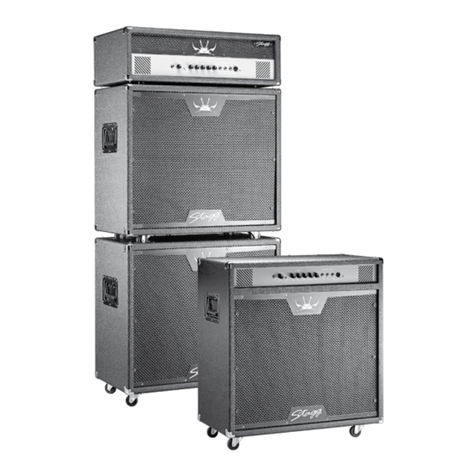
Stagg SPA-SUB 1208 EUR User manual

1
USER GUIDE
MULTI PURPOSE AMPLIFIED SPEAKER CABINETS
SPA-SUB 1208 EUR
SPA-SUB 1510 EUR
SPA-SUB 1512 EUR
SPA-SUB 1810 EUR

2
3
• This active speaker system must be connected to a mains (AC) outlet to work properly and must
be earthed to operate safely.
• Ensure that correct AC mains voltage and socket - tted with a real ground connection – are
available before powering up the unit.
• Check mains power cable and plugs before switching on the equipment.
If the mains cable and/or plug are damaged, replace the whole cable immediately.
For your own and other people’s safety, never repair or modify the mains power cable.
Dispose of the defective cable properly for waste and recycling purpose.
• After following the instructions outlined above, if your powered speaker fails to function, please
contact your vendor.
Under no circumstances should the cabinet be opened. Leave all servicing to qualied personnel.
• Electrical appliances must never be used in conditions of high humidity or heat.
To prevent any risk of re or electric shock, never spill or splash liquids on the amplier.
Should this happen, unplug the power cable from the mains outlet and switch off the powered
speaker immediately.
• May we draw your attention to the instructions printed on the rear panel of the cabinet.
WARNING: Exposure to extremely high noise levels may cause permanent hearing damage.
Please use this amplied speaker responsibly for you and your neighbourhood.
• The CE mark on this product means it conforms to the EMC Directive (2004/108/CE), CE marking
Directive (93/68/EEC) and Low Voltage Directive (2006/95/EC).
• The “Crossed-out Wheelie Bin” is featured to draw your attention to the WEEE (Waste Electric &
Electronic
Equipment) Directive (2002/96/EC). It means this apparatus must be collected separately for recycling.
• “RoHS compliant” means this device conforms to the (2002/95EC) Directive on the restriction of the use of
certain hazardous substances in electrical and electronic equipment, such as: Mercury, Lead, Cadmium,
Hexavalent Chromium, Polybrominated Buphenyl (PBB) and Polybrominated
Diphenyl Ethers (PBDE).
READ AND KEEP THESE INSTRUCTIONS. HEED ALL WARNINGS.
IMPORTANT SAFETY INSTRUCTIONS
MARKING & CONFORMITY
RoHS
compliant

2
3
Thank you for purchasing your new Stagg SPA SUB Powered PA system.
Stagg SPA SUB series powered PA SYSTEMS with SUB WOOFER are designed as compact, full-range,
multi-purpose active PA speaker systems with output powers ranging from true 300 + 2x80 to 700 + 2x200
Watts RMS.
The subs are on wheels and the two top speakers nest on top of the subwoofer for easy transportation.
The cabinet of the SUB WOOFER hosts the woofer and its power amp, the electronic crossover and two
amps that drive the two separate mid-high speakers.
The Stagg SPA-SUB 1208 consists of a sub cabinet with a 12” woofer and two satellites with a 8” mid
speaker and a compression horn tweeter.
The Stagg SPA-SUB 1510 consists of a sub cabinet with a 15” woofer and two satellites with a 10” mid
speaker and a compression horn tweeter.
The Stagg SPA-SUB 1512 consists of a sub cabinet with a 15” woofer and two satellites with a 12” mid
speaker and a compression horn tweeter.
The Stagg SPA-SUB 1810 consists of a sub cabinet with a 18” woofer and two satellites with a 10” mid
speaker and a compression horn tweeter.
Stagg SPA-SUB PA systems each consist of a sub cabinet and two satellites.
The sub cabinet has 4 sturdy wheels for easy transport. To use the cabinet, it has to be put on the rubber feet
so that the controls and in/outputs become accessible on the rear.
The two satellite cabinets have a standard 35mm built-in pole mount socket for use with a tripod-style stand
and a built-in handle.
As mentioned above, the satellites nest in the sub when the latter is on its wheels.
FOREWORD
MECHANICAL FEATURES
3
As mentioned above, the satellites nest in the sub when the latter is on its wheels.

4
5
TECHNICAL SPECIFICATIONS
Specifi cation SPA-SUB1208 SPA-SUB1510
Subwoofer Subwoofer
Woofer speaker
12”*1, aluminum
frame,75mm voice
coil, 100oz
15”*1, aluminum
frame,100mm voice
coil,125oz
Frequency Range 40Hz-130Hz 40Hz-130Hz
Impedance 8 Ohm 8 Ohm
Sensitivity (1m/1W) 92dB 95dB
Max SPL 107dB 117dB
Output Power 1*300W 1*500W
Speaker Speaker
Mid speaker 8”steel frame, 38mm
voice coil, 23oz
10” steel frame, 50mm
voice coil, 40oz
Tweeter 1.25” 1.25”
Frequency Range 65Hz-20kHz 60Hz-20kHz
Impedance 8 Ohm 8 Ohm
Sensitivity (1m/1W) 90dB 92dB
Max SPL 111dB 115dB
RMS Power for speaker 100W 200W
Output Power 2*80W 2*120W
Specifi cation SPA-SUB1512 SPA-SUB1810
Subwoofer Subwoofer
Woofer speaker
15”*1, aluminum
frame,100mm voice
coil,125oz
18”*1, aluminum
frame,100mm voice
coil,125oz
Frequency Range 40Hz-130Hz 40Hz-130Hz
Impedance 8 Ohm 8 Ohm
Sensitivity (1m/1W) 95dB 97dB
Max SPL 117dB 126dB
Output Power 1*500W 1*700W
Speaker Speaker
Mid speaker 12” steel frame,
65mm voice coil, 50oz
10” steel frame, 50mm
voice coil, 40oz
Tweeter 1.25” 1.25”
Frequency Range 55Hz-20kHz 60HZ-20kHz
Impedance 8 Ohm 8 Ohm
Sensitivity (1m/1W) 95dB 92dB
Max SPL 118dB 115dB
RMS Power for speaker 250W 200W
Output Power 2*120W 2*200W
Features and Specifi cations are subject to change without notice.

4
5
OPERATING INSTRUCTIONS
THE Stagg SPA-SUB sets are active sets, which means they have all necessary power amps on board.
The only thing you need to do to make them work is connect audio signals to the inputs on the control panel
of the sub, connect the 2 satellite speakers with speaker cables to the sub, connect the mains cable, switch
on the unit and adjust the volumes of sub speaker and satellites.
The signal fl ow in the SUB PA is as follows:
The full-range left and right signals go into the sub and are separated into a left and right low and a left and
right mid-high signal. The left and right low signals are mixed together and pass trough a limiter, then are
ampli ed and sent to the woofer in the sub cabinet. The left and right mid & high signals pass each trough a
limiter, then are ampli ed separately and sent to the 2 satellites. In the satellites the signal is separated again
into mid and high and sent respectively to the internal mid speaker and horn tweeter.
We will now show you step by step how to get the best results.
1 234 43
The inputs (1) and (2) are a combination of a phone plug and XLR plug. In the middle there is a ¼
phone jack (1); The female XLR input is in the outer ring (2) . The use of the balanced XLR input is
recommended over the use of the unbalanced phone plug input as noise levels will be much lower.
1. JACK INPUTS: These high impedance ¼” jack sockets accept unbalanced signals. We recommend the
use of a high-quality shielded audio cable to prevent any background noise interference or unwanted feedback.
2. XLR INPUT: These line level, balanced female XLR connectors are designed to only accept signals from line
level equipment with balanced output such as a mixing console, a tape machine, or another Powered Speaker
Cabinet. When the distance between the external audio device and the powered speaker cabinet exceeds 15
feet, a balanced cable should preferably be used to minimize signal loss. Wiring of the 3-pin connector is: Pin 1=
Shield; Pin 2 = Positive (Hot); Pin 3 + Negative (Cold).
3. XLR OUT: These low impedance line outputs with XLR male connectors can be connected to an other active
speaker or sub set with a balanced input
4. Speaker OUT: These speaker out connectors are used to sent the ampli ed mid/high signals to the satellites.
In- and outputs

6
7
11 141312
9 8
10 15 65 7

6
7
5. SUB WOOFER LEVEL: This control determines the volume of the low frequencies .
6. CLIP LED: This 3 colour LED shines green as long as the limiting device is not “limiting” the low signal. The
LED shines orange when the signal starts to be limited to avoid distortion. This happens when the signal to the
output power stage becomes too loud. When the limiter performs to its maximum the LED permanently lights up
red; it indicates distortion that could be harmful for the speakers. This means that one or more levels are set too
high and should be at once re-adjusted until the led fl ashes again or shuts off.
7. Phase inverter: As the name suggests it inverts the phase of the signal. When speakers perform not in
phase some information will be acoustically lost. (for example: one speaker moves forward and at the same time
an other moves backward, the result is that little air moves and the volume will be low)
8. MID - HIGH LEVELS: These controls determine the volume of the mid high frequencies sent to the satellites.
9. CLIP LED’s: These 3 colour LED’s shine green as long as the limiting device is not “limiting” the mid high
signals. The LED’s shine orange when the signal starts to be limited to avoid distortion. This happens when
the signal to the output power stage becomes too loud. When the limiter performs to its maximum the LED
permanently lights up red; it indicates distortion that could be harmful for the speakers. This means that one or
more levels are set too high and should be at once re-adjusted until the led becomes orange or green.
10. GROUND LIFT: With ground lift you can eliminate or reduce noise generated by earth loops. Earth loops
happen when equipment is earthed on several places and current fl ows in the cable shields. So by pushing the
button you can interrupt the earth connection. For safety reasons, make sure that one earth connection is left
in place.
11. POWER SWITCH: This switch turns the active speaker set on or off. When on, the power LED on the top
lights up.
12. POWER FUSE: In the event of the power fuse having to be replaced, rst unplug the power cable from the
mains outlet. Then remove the fuse cover and replace the power fuse with one of the same type and value. Never
plug the power cable back into the mains outlet without the fuse cover. When powering on the ampli er, if the
power fuse blows up again, go to a suitable service centre for repair.
13. AC (MAINS) INPUT: This is the input socket into which the moulded mains power cable must be connected.
If the socket outlets available are not suitable for the plug supplied with this equipment, use an appropriate plug
adapter that can handle the power required for this powered speaker.
14. FAN: This fan will cool the 3 power ampli ers that are built in .
15. POWER LED: Is lit up when the SPA SUB PA speaker set is switched on.
CONTROLS
MAINS SECTION

8
DISTRIBUTOR / DEALER
EMD Music 10-2010-UK
This manual suits for next models
3
Table of contents
Other Stagg Amplifier manuals
Stagg
Stagg KBA 40 User manual
Stagg
Stagg 60 GA DSP User manual
Stagg
Stagg 40 BA USA User manual
Stagg
Stagg 40 BA User manual

Stagg
Stagg 20 BA User manual
Stagg
Stagg 20 BA USA User manual
Stagg
Stagg 60 BA USA User manual
Stagg
Stagg 10 AA USA User manual
Stagg
Stagg 40 GA DSP User manual

Stagg
Stagg 10 AA User manual
Stagg
Stagg 40 AA R USA User manual
Stagg
Stagg 40 AA R User manual
Stagg
Stagg 15 GA DR User manual
Stagg
Stagg 20 AA R User manual

Stagg
Stagg EDA 40 User manual
Stagg
Stagg 10 GA User manual
Stagg
Stagg 60 AA R User manual
Stagg
Stagg 60 GA DSP USA User manual
Stagg
Stagg 15 GA DR USA User manual
Stagg
Stagg SMS8P User manual
