Stagnoli A24 User manual

1
A24
IT
EN
FR
DE
COM
STA
PHO
1
PHO
1+2
STOP
PED
+24V- M1 S1 + 5V - S2 M2
24VAC
COMFCO FCC
ANT
E
0000
Stagnoli s.r.l. - via Mantova Traversa 1, 105 a/b
25017 Lonato - Brescia - Italia
tel (+39) 030.9139511 fax (+39) 030.9139580
www.stagnoli.com
Moving Ideas.
ISTRUZIONI CENTRALE DI COMANDO A24
CONTROL UNIT A24 INSTRUCTIONS
INSTRUCTIONS CENTRALE DE COMMANDE A24
BEDIENUNGSANLEITUNG STEUERZENTRALE A24

9
EN
COM
STA
PHO
1
PHO
1+2
STOP
PED
+24V- M1 S1 + 5V - S2 M2
24VAC
COMFCO FCC
ANT
E
0000
FUSE
L N
5
9
8 7 6
10
11
12 13 14 15 16 17 18
4
1
3
2
INSTALLATION AND PROGRAMMING INSTRUCTIONS
This manual is intended for qualied technical personnel responsible for installations.
Please read these instructions carefully prior to installation.
Improper use of the product or a connection error could affect proper operation and end user safety.
Supply power: 230V ~ ±10% - 50Hz
On-board 433MHz receiver: 76 transmitters MAX
Operating temperature: -20°C / +60°C
Electronic anti-crushing device: amperometric + encoder
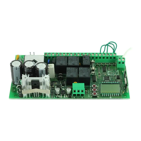
DESCRIPTION OF PARTS
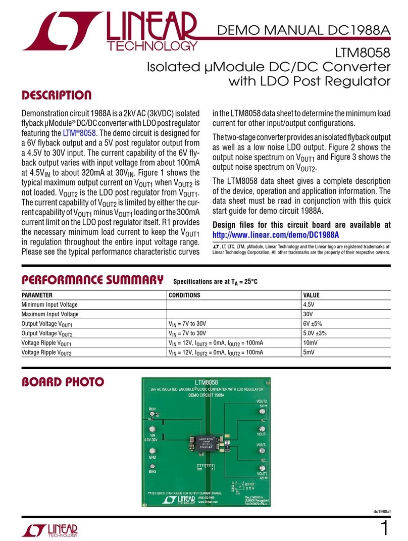
1- Line fuse 230V (T2.5A 5x20)
2- Terminal board for transformer line connection
3- Primary transformer 230V, secondary 24V~, 130VA
4- Molex power 24 V~, and hole for auxiliary grounding (to be welded)
5- Supply power fuse, (F10A 5x20)
6- Terminal board for mechanical/magnetic limit stop (ONLY for pre-set models)
7- Menu navigation buttons
8- 4-language LCD display (IT,EN,FR,ES)
9- Receiver model 433Mhz Rollingcode/xed code
10- Terminal for external antenna
11- Auxiliary power fuse 24Vac, (F2A 5x20)
12- Terminal board for control and safety connection
13- Auxiliary power 24V~, (24Vdc with battery supply power)
14- Steady light ashing light power, 24V~ (24Vdc with battery supply power)
15- Motor 1 connection
16- Encoder supply power 5Vdc
17- Motor 2 connection
18- Electric lock 12Vdc 10W (max 2 sec)
FIG 1
TECHNICAL DATA
MAX ashing light output power: 24V~ - 25W
MAX electric lock output power: 12Vdc - 10W (max 2 Sec)
Accessory supply power 24V~ - 25W
Maximum motor power current: 3.5A+3.5A
The “H24” 24V version control unit is for use on automatic residential and condominium sliding gates for intensive use. Any use differing from
that described herein or installations performed differently from that set forth in the following technical manual are prohibited.
INTENDED USE AND LIMITATIONS OF USE

10 www.stagnoli.com
COM
STA
PHO
1
PHO
1+2
STOP
PED
+24V- M1 S1 + 5V - S2 M2
24VAC
COMFCO FCC
ANT
E
0000
M1 ENCODER
1
ENCODER
2M1
FUSE
Board
Trasfor
Automatic
Manual
Battery
- 24V +
- +
BATTERY
12V
- +
BATTERY
12V
COM
STA
PHO
1
PHO
1+2
STOP
PED
+24V-
M1 S1 + 5V - S2 M2
24VAC
COMFCO FCC
ANT
E
0000
HERMES200/250
START
COMMON
PHOTOC. CLOSES
PHOTOC. OPENS AND
CLOSES
STOP
PED.
*ENCODER WIRING
green = signal
white = -
brown = +
FIG 2
Caution!
Electrical connections must be made with power cut off
and with the battery charger kit disconnected, where present.
RED M1
BLUE M1
GREEN M1
BROWN M1 E M2
WHITE M1 E M2
GREEN M2
RED M2
BLUE M2
ELECTRICAL CONNECTIONS

11
x4
1
2
1
2
1
2
1
2
1
2
1
2
ABC
DEF
1
2
1
2
1
2
GHI
NAVIGATING THE MENU
Keep the following in mind when navigating inside the menu:
- if button “E” is pressed for 1s it functions as an “ENTER” button while if it is pressed for 3s it functions as an “ESC” button
- the control unit does not give any regard to control signals when the user is inside the menu
As shown, the home screen contains a code where
the rst and second character indicate the respective position of Motor 1 and Motor 2:
o= open
c= closed
The last two digits indicate the number of TX stored.
oc00
ADD ITA R 00
-
-
SETTING THE LANGUAGE
Stagnoli control units are available in 4 different languages:
ITALIAN - ENGLISH - FRENCH - SPANISH
The default language on the control unit is English. To change language, access the menu by pressing button "E", then press the down arrow
four (4) times and then "E" again. Then use arrows to choose the desired language and press "E".
With this operation, the control unit will store encoder impulses and the forces necessary to
complete both opening and closing stroke on swing leaf gates.
Before carrying out SELF-LEARNING, set single motor operation, if necessary, selecting "FUNCTIONS" from the menu and set parameter “1M”
to “1”, otherwise the control unit is set to manage 2 motors as default.
Before carrying out SELF-LEARNING, adjust the mechanical stops (where present) according to needs.
Note: SELF-LEARNING must be repeated whenever stops are adjusted.
To perform SELF-LEARNING:
1. Unlock motors.
2. Bring gate leaves to open position.
3. Lock motors.
4. Go to "SELF-LEARNING" in the menu and press button "E".
5. The operation includes a complete closing, opening and closing cycle, specically:
a. leaf 2 starts to close, followed by leaf 1 after about 3s
b. both leaves re-open: rst leaf 1, followed by leaf 2 after about 1s
c. leaf 2 starts to close, followed by leaf 1 after about 3s
The operation is completed leaving the leaves closed and with display of the message “OK” if it has been successful.
Otherwise, the display will show the message “ERR”.
6. To conrm self-learning success, simply press button "E", which will bring you back to the main screen.
SELF-LEARNING FOR SWING GATES
CC00 Appr ATTE
OK CC00
oC00 lang

12 www.stagnoli.com
a 1.01 0123 4567 0000 0000
1212
oc00
ADDITION OF RADIO
CONTROL REGULATING FUNC-
TIONS CANCEL LEARNING
1Ch
2ch
TCA
Tped
SFAP
SFCH
ralL
FAP
FCH
VEL
SBA
Tinv
TAUX
CA
BA
BP
cr
2p
PL
1m
oc
CF
AR
Automatic closing
time [S]
Pedestrian
opening [%]
Delay in opening
time of M2 [S]
Delay in closing
time of M1 [S]
Slowing
space [1x10cm]
Opening force
[%]
Closing force [%]
Movement
speed
Strike space [cm]
Relax time
[1x10ms]
Electric lock time
[S]
Automatic
closing
Blocks impulses
during opening
Blocks impulses
during pause
Rapid closing
Open/close
operation
Preashing
Operation with 1
motor
OPEN/CLOSE
MANNED
operation
Fixed code
enable
Ramming
operation
RESET
Canc 1 tx
canc all
Reset parameters
Erase 1
transmitter
Cancel all
transmitters
Channel 1,
START impulse
Channel 2,
PED impulse
MENU DIAGRAM
LAN-
GUAGE
ITALIANO
ENGLISH
FRANCAIS
ESPANOL
press and hold
Consumption diagnostics
Software diagnostics
Software version cycle counter stroke stored
motor 1 stroke stored
motor 2
torque motor 1 in % (rst 2 digits)
torque motor 2 in % (second 2 digits)
press once
press
once
Tipe Motor type

13
R 00
-
-AGG 1 ch PREM
MEMORISING ONE OR MORE RADIO CONTROLS
Press the
transmitter button. ok
Stagnoli control units can memorise 76 transmitters per channel in both rollingcode and xed code. They are set by default to memorise Stagnoli
Rollingcode transmitters. To memorise xed codes, modify “CF” parameters in the "FUNCTIONS" menu.
In addition, Stagnoli control units provide two memory channels:
1- the rst channel controls automation: open-stop-close (or as programmed)
2- the second is used for pedestrian opening
TCA
TPED
Default: 10sec
Min: 1sec
Max: 240sec
Default: 50%
Min: 30%
Max: 99%
FAP
FCH
Default: 50
Min: 20
Max: 99
Default: 50
Min: 20
Max: 99
Trel Default: 2
Min: 0
Max: 20
SFAP Default: 1 sec
Min: 0 sec
Max: 10 sec
SFCH Default: 3 sec
Min: 0 sec
Max: 10 sec
rall Default: 2
Min: 1
Max: 10
VEL Default: 5
Min: 1
Max: 10
sba Default: 4
Min: 1
Max: cm
tAUX Default: 1 sec
Min: 0 sec
Max: 2 sec
(automatic closing time)= This is the time from when the gate is fully open to when it is closed,
which is automatic if CA=1. If the photocell is engaged, count time is reset.
(pedestrian opening)= This is the length of the pedestrian stroke (partial opening of leaf 1) ex-
pressed in % in reference to the total stroke.
DESCRIPTION OF PARAMETERS
(anti-crushing force of leaf in opening)= This is the anti-crushing force of the leaf of the gate
stated in % compared with the maximum force in the opening phase. **
(anti-crushing force of leaf in closing)= This is the anti-crushing force of the leaf of the gate stat-
ed in % compared with the maximum force in the closing phase. **
(relax time)= When the motor arrives at limit stop, both in opening and in closing, the direction of
travel is reversed for the set time, relaxing mechanical components
Equals: 1x10ms
(delay in opening time)= Delay time in seconds for leaf 2 opening.
(delay in closing time)= Delay time in seconds of leaf 1 closing.
(slowing space)= Space where stroke slows down both in opening and in closing,
Equals: 1x10cm.
(movement speed)= Movement speed\ (this parameter also automatically modies slowing
speed).
(strike space)= This is the space, expressed in cm, at the tip of the leaf before the stop in open-
ing and closing in which the control unit interprets obstacles as limit stops.
(electric lock time)= This is the electric lock power supply time.
** Stagnoli control units automatically memorise the forces necessary (FCH and FAP) for gate leaf movement, adding 10% to the average forces
detected during self-learning. Stagnoli delegates the correct setting of anti-crushing forces (FCH and FAP) in accordance with standard EN
12445 to installers.

14 www.stagnoli.com
1m Default: 0
Off: 0
On: 1
(1 motor operation)= Managed only by motor 1 if enabled.
oc
cf
Default: 0
Default: 0
Off: 0
On: 1
(open/close function)= If set to 1, the open/close function dedicates START function solely to
START input and PEDESTRIAN input takes on the sole function of CLOSE. The PEDESTRIAN
and START functions remain the same for transmitters.
If set to value 2, pedestrian input function will be dedicated to the "manned" function.
(xed code)= If activated, the control unit is enabled to memorise HT53200 xed code radio
controls.
AR Default: 0
Off: 0
On: 1
(ramming in opening) = Before starting opening, motor 1 pushes the leaf closed, allowing the
electric lock to move away from the stop. At this point, the lock activates and movement continues
regularly in opening.
FC Default: 0
Off: 0
On: 1
(limit stop) = To be used only with sliding gates; if active, the control unit enables limit stop (NC)
input in corresponding terminal boards.
(manages only 1 gate wired on motor 1)
2P
PL
Default: 0
Off: 0
On: 1
Default: 0
Off: 0
On: 1
(open/close operation)= If enabled, at each START impulse, the movement of the gate changes
direction. If not enabled, gate movement sequence becomes:
OPEN>STOP>CLOSE>STOP and TTCA is not entered
(Preashing)= Flashes 2 sec before movement starts.
CR Default: 0
Off: 0
On: 1
(rapid closing)= If photocells are activated in opening or with the gate open, TTCA pause time is
reduced to 3 sec.
DESCRIPTION OF THE CANCEL MENU
RESET
ERASE 1 tx
The menu reset option CANCEL resets all parameters and functions with default settings. Once you have entered into the
CANCEL menu, go to RESET by pressing ENTER. The display will begin to ash as it awaits conrmation. Press ENTER
again to reset to default parameters. If not, exit. If you press ENTER, the message PRG will appear on the screen to indi-
cate that resetting is in progress.
To erase a radio control from Stagnoli control units, it is necessary to have the radio control on hand. Enter the ERASE 1
TX option and press the button of the transmitter that must be cancelled. If this button is not found, the control unit will give
an ERR message; if it is found, it will be erased and we will see the message OK on the display.
ERASE all tx This option gives the possibility of erasing all radio controls from memory, both on channel 1 and channel 2.
DESCRIPTION OF ACCESSORY DIAGNOSTICS
The control unit can recognise problems or alarms that can occur in the
system; therefore it can signal some messages on the main display to
allow the problem to be identied:
•1 rf= activation of the START command on the rst radio frequency channel.
•2 rf= activation of the PEDESTRIAN command on the second radio frequency channel.
•sta= activation of the START command on terminal board input.
•ped= activation of the pedestrian input command.
•stO= activation of the STOP command on the terminal board input.
•phO= activation of photocells input in closing on the terminal board.
•phA= activation of photocells input in opening and in closing on the terminal board.
•bar= activation of the safety rib.
•sUo= activation of limit stop input in opening.
•sUc= activation of limit stop input in closing.
•am 1= activation of the amperometric sensor on the rst motor.
•enc1= operation of the sensor with encoder on the rst motor.
•prg= adjustment or function programming in progress.
•OK= successful operation.
•ERR= failed operation.
•full= radio control memory full.
•attendi= pause wait.
•tout= wait time up.
DESCRIPTION OF FUNCTIONS
CA
Ba
Default: 1
Off: 0
On: 1
Default: 0
Off: 0
On: 1
(automatic closing)= If enabled, the gate automatically re-closes after TTCA time is completed.
(blocks impulses during opening)= The control board ignores the START impulses during the
opening phase.
BP Default: 0
Off: 0
On: 1
(blocks impulses during pause)= The control board ignores the START impulses during the
pause phase.

15
TCA TPED SFAP SFCH TRAL FAP
FCH VEL FBA SBA TINV TAUX
ca ba BP CR 2p PL 1m oc cf ar fc
IMPORTANT WARNINGS AND FIRST START-UP
DISPOSAL
Always perform nal testing after having completed all programming:
• Unlock motors and make sure that the leaves move freely with a force lower than 390Nm, then re-lock them.
• Check correct operation of protective devices (anti-crushing system, stop button, photocells, etc.).
• Check correct operation of signalling devices.
• Check correct operation of control devices (radio controls, selectors, etc.).
• Adjust motor working forces (FCH and FAP) in accordance with standard EN 12445 to ensure system safety.
This product is composed of various components which in turn may contain pollutants. Do not litter! Inquire about recycling or disposal of prod-
ucts according to the laws in force at the local level.
IMPORTANT WARNINGS ABOUT INSTALLATION:
• Automatic gate systems must be installed by qualied technical staff in compliance with legal requirements and meeting the requirements of
the law and in conformity with Machinery Directive 98/37/EC and standards EN13241-1, EN 12453 and EN 12445.
• Verify the solidity of existing structures (columns, hinges, leaves) in relation to forces developed by the motor.
• Verify the conditions of any cables already present in the system.
• Analyse automation risks and take the necessary safety and signalling precautions accordingly.
• Install controls (for example key selectors) to keep users out of danger zones.
• Once installation has been completed, test safety, signalling and automation unlocking devices a few times (see FINAL TESTING).
• Make sure that users have understood correct automatic, manual and emergency operation of automation.
FIRST START-UP:
• Draft a system technical le containing: Installation drawing, Wiring diagram of connected cables, analyses of risks present and adopted
solutions, analyses of residual risks still present, declaration of conformity of all products drafted by the manufacturer and a declaration of
conformity relative to installation completed by the installer.
• Afx the CE label or plate containing hazard information and identifying data (serial number, etc.) to the machine.
• Deliver instructions for use, safety warnings, CE declaration of conformity and a copy of the technical le to the end user.
Also make sure to inform the end user:
• regarding the possible presence of unprotected residual risks and foreseeable improper use
• of the importance of disconnecting power supply when performing cleaning in the automation area or when performing small maintenance
operations (i.e. repainting)
• on the need to frequency verify that there is no visible damage to automation or, if any is detected, to immediately alert the installer
• with regards to the danger of letting children play in the immediate vicinity of automation
• Prepare a system maintenance schedule (at least every 6 months for safety devices), keeping notes regarding operations performed in a
log.
FINAL TESTING
We recommend using the spaces below to write down the parameters you have customised.
NOTES:
NOTES ON PARAMETERS AND FUNCTIONS:
Other manuals for A24
1
Table of contents
Other Stagnoli Control Unit manuals
Popular Control Unit manuals by other brands

Bosch
Bosch Rexroth H-4WEH...XE Series operating instructions

Polycom
Polycom SoundPoint IP 670 quick start guide

Honeywell
Honeywell NOTIFIER M701E installation instructions

ABB
ABB FCAN-01 Quick installation and start-up guide

Agilent Technologies
Agilent Technologies G4315A installation guide

Murata
Murata MAGICSTRAP LXMS Series Application guide