Stagnoli A24 User manual

1
A24
IT
EN
FR
DE
COM
STA
PHO
1
PHO
1+2
STOP
PED
+24V- M1 S1 + 5V - S2 M2
24VAC
COMFCO FCC
ANT
E
0000
Stagnoli s.r.l. - via Mantova Traversa 1, 105 a/b
25017 Lonato - Brescia - Italia
tel (+39) 030.9139511 fax (+39) 030.9139580
www.stagnoli.com
Moving Ideas.
ISTRUZIONI CENTRALE DI COMANDO A24
CONTROL UNIT A24 INSTRUCTIONS
INSTRUCTIONS CENTRALE DE COMMANDE A24
BEDIENUNGSANLEITUNG STEUERZENTRALE A24

2www.stagnoli.com
IT
COM
STA
PHO
1
PHO
1+2
STOP
PED
+24V- M1 S1 + 5V - S2 M2
24VAC
COMFCO FCC
ANT
E
0000
FUSE
L N
5
9
8 7 6
10
11
12 13 14 15 16 17 18
4
1
3
2
Tutti i dati e le informazioni quì contenute sono da ritenersi suscettibili di modica in qualsiasi momento e a nostro insindacabile giudizio
cod.: X51AXXX - rev.: 1.0 - data: 3/2013
ISTRUZIONI PER L’INSTALLAZIONE E LA PROGRAMMAZIONE.
Il presente libretto è destinato al personale tecnico qualicato alle installazioni
Prima di eseguire l’installazione consigliamo di leggere attentamente la presente istruzione.
Un uso improprio del prodotto o un errore di collegamento potrebbe pregiudicare il corretto funzionamento dello stesso e la sicurezza dell’utente
nale.
Alimentazione: 230V ~ ±10% - 50Hz;
Ricevitore integrato 433MHz: 76 trasmettitori MAX;
Temperatura di funzionamento: -20°C / +60°C;
Dispositivo elettronico antischiacciamento: amperometrica + encoder
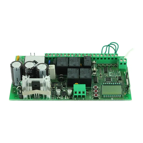
DESCRIZIONE DELLE PARTI
1- Fusibile di linea 230V (T2,5A 5x20)
2- Morsettiera per il collegamento della linea al trasformatore
3- Trasformatore primario 230V, secondario 24V~, 130VA
4- Molex alimentazione 24 V~, e foro per messa a terra (da saldare) ausiliaria
5- Fusibile alimentazione, (F10A 5x20)
6- Morsettiera per necorsa meccanici/magnetici (SOLO per modelli predisposti)
7- Tasti per la navigazione nel menù
8- Diplay LCD 4 lingue (IT,EN,FR,ES)
9- Modulo ricevitore 433Mhz Rollingcode/codice sso
10- Morsetto per l’antenna esterna
11- Fusibile alimentazione ausiliaria 24Vac, (F2A 5x20)
12- Morsettiera per collegamento comandi e sicurezze
13- Alimentazione ausiliaria 24V~, (24Vdc con alimentazione a batterie)
14- Alimentazione lampeggiante luce ssa, 24V~ (24Vdc con alimentazione a batterie)
15- Collegamento motore 1
16- Alimentazione encoder 5Vdc
17- Collegamento motore 2
18- Elettroserratura 12Vdc 10W (max 2sec)
FIG 1
DATI TECNICI
Potenza MAX dell’uscita lampeggiante: 24V~ - 25W;
Potenza MAX dell’ uscita elettroserratura: 12Vdc - 10W (max 2 Sec);
Alimentazione accessori 24V~ - 25W;
Corrente massima di alimentazione motori: 3,5A+3,5A;
La centrale “H24” è destinata ad automatizzare cancelli scorrevoli, a 24V, di tipo residenziale e condominiale anche per uso intensivo. Ogni uso,
diverso da quanto sopra descritto ed installazioni in modalità diverse da quanto esposto nel seguente manuale tecnico, sono da considerarsi
vietate.
DESTINAZIONE E LIMITI D’USO

3
COM
STA
PHO
1
PHO
1+2
STOP
PED
+24V- M1 S1 + 5V - S2 M2
24VAC
COMFCO FCC
ANT
E
0000
M1 ENCODER
1
ENCODER
2M2
FUSE
Board
Trasfor
Automatic
Manual
Battery
- 24V +
- +
BATTERY
12V
- +
BATTERY
12V
COM
STA
PHO
1
PHO
1+2
STOP
PED
+24V-
M1 S1 + 5V - S2 M2
24VAC
COMFCO FCC
ANT
E
0000
HERMES200/250
START
COMUNE
FOTOC. CHIUDE
FOTOC. APRE E CHIUDE
STOP
PED.
*CABLAGGI ENCODER
verde = segnale
bianco = -
marrone = +
FIG 2
Attenzione!
I collegamenti elettrici vanno eseguiti in assenza di alimentazione,
e con il kit caricabatterie scollegato, ove presente.
ROSSO M1
BLU M1
VERDE M1
MARRONE M1 E M2
BIANCO M1 E M2
VERDE M2
ROSSO M2
BLU M2
COLLEGAMENTI ELETTRICI

4www.stagnoli.com
x4
1
2
1
2
1
2
1
2
1
2
1
2
ABC
DEF
1
2
1
2
1
2
GHI
MUOVERSI NEL MENÙ
Per muoversi all’interno del menù è bene tenere presente che:
- il pulsante “E“ se premuto per 1s funziona da “ENTER” mentre se viene premuto per 3s funziona da “ESC”;
- quando siamo all’interno del menù la centrale non considera nessun segnale di comando;
La schermata iniziale come è illustrato, riporta una sigla dove
il primo ed il secondo carattere indicano la posizione rispettivamente del Motore 1 e del Motore 2:
o = aperto;
c = chiuso;
Le ultime due cifre indicano il numero di TX memorizzati.
oc00
AGG ITA R 00
-
-
IMPOSTARE LA LINGUA
Le centrali Stagnoli ti permettono di scegliere tra 4 lingue diverse:
ITALIANO - INGLESE - FRANCESE - SPAGNOLO
La centrale di default è impostata in inglese, per cambiare lingua accedere al menù premendo il tasto “E” poi premere quattro (4) volte la freccia
verso il basso, e nuovamente “E”; a questo punto con le frecce scegliere la lingua e premere “E”.
Con questa manovra la centrale memorizzerà gli impulsi dell’encoder e le forze necessarie al
completamento della corsa, sia in apertura che in chiusura, sui cancelli con ante a battente.
Prma di eseguire l’AUTOAPPRENDIMENTO settare, se necessario, il funzionamento a motore singolo selezionando nel menù “FUNZIONI” il
parametro “1M” su “1”, altrimenti la centrale di default è impostata per la gestione di 2 motori.
Prima di eseguire l’AUTOAPPRENDIMENTO regolare i fermi meccanici (ove previsti), secondo le proprie esigenze.
N.B.: Ogni volta che i fermi vengono regolati è necessario ripetere l’AUTOAPPRENDIMENTO.
Per eseguire l’AUTOAPPRENDIMENTO:
1. sbloccare i motori
2. portare le ante in posizione di apertura;
3. bloccare i motori
4. andare alla voce di menù “AUTOAPPRENDIMENTO” e premere il pulsante ”E”
5. la manovra comprende un ciclo completo di chiusura, apertura e chiusura nello specico:
a. l’anta 2 parte in chiusura seguita dall’anta 1 dopo circa 3s,
b. entrambe le ante si riapriranno per prima l’anta 1 seguita dall’anta 2 dopo circa 1s.
c. l’anta 2 parte in chiusura seguita dall’anta 1 dopo circa 3s,
la manovra si conclude lasciando le ante chiuse e facendo comparire sul display la scritta “OK” se tutto è andato a buon ne,
altrimenti “ERR”.
6. per confermare la riuscita dell’autoapprendimento basterà premere il pulsante “E” che ci farà tornare alla schermata principale.
AUTOAPPRENDIMENTO PER CANCELLI A BATTENTE
CC00 Appr ATTE
OK CC00
oC00 ling

5
a 1,01 0123 4567 0000 0000
1212
oc00
AGGIUNTA
RADIOCOMANDO REGOLAZIONI FUNZIONI CANCELLA APPRENDIMENTo
1Ch
2ch
TCA
Tped
SFAP
SFCH
ralL
FAP
FCH
VEL
SBA
Tinv
TAUX
CA
BA
BP
cr
2p
PL
1m
oc
CF
AR
Tempo chiusura
automatica [S]
Apertura
pedonale [%]
Sfasamento M2
in apertura [S]
Sfasamento M1
in chiusura [S]
Spazio di
rallentamento
[1x10cm]
Forza in apertura
[%]
Forza in chiusura
[%]
Velocità di
manovra
Spazio di battuta
[cm]
Tempo di relax
[1x10ms]
Tempo alettroser-
ratura [S]
Chiusura
automatica
Blocco impulsi in
apertura
Blocco impulsi in
pausa
Chiusura rapida
Funzionalità
apri/chiudi
Prelampeggio
Funzionalità ad
1motore
Funzionamento
OPEN/CLOSE/
UOMOPRESENTE
Abilitazione
codice sso
Funzionalità
ariete
RESET
Canc 1 tx
canc tutti
Reset dei para-
metri
Cancella 1
trasmettitore
Cancella tutti i
trasmettitori
Canale 1, impul-
so di START
Canale 2, im-
pulso di PED
DIAGRAMMA MENU
LINGUA
ITaliano
ENGLISH
FRANCAIS
ESPANOL
tenere premuto
Diagnostica consumi
Diagnostica software
Versione software contatore cicli corsa memo-
rizzata
motore 1
corsa me-
morizzata
motore 2
coppia motore 1 in % (prime 2 cifre)
coppia motore 2 in % (seconde 2 cifre)
pressione semplice
pressione
semplice
Tipe Tipo motore

6www.stagnoli.com
R 00
-
-AGG 1 ch PREM
MEMORIZZARE UNO O PIÙ RADIOCOMANDI
Premere il pulsante
del trasmettitore. ok
Le centrali Stagnoli possono memorizzare 76 trasmettitori per canale, sia rollingcode che codice sso, di default sono abilitate alla memorizza-
zione di trasmettitori con rollingcode Stagnoli, per la memorizzazzione di codici ssi bisogna modicare il parametro “CF” nel menù “FUNZIONI”.
Inoltre le centrali Stagnoli mettono a disposizione due canali di memorizzazione:
1- il primo canale è per il controllo dell’automazione: apri-stop-chiudi (o come da programmazione)
2- il secondo invece serve per l’apertura pedonale;
TCA
TPED
Default: 10sec
Min: 1sec
Max: 240sec
Default: 50%
Min: 30%
Max: 99%
FAP
FCH
Default: 50
Min: 20
Max: 99
Default: 50
Min: 20
Max: 99
Trel Default: 2
Min: 0
Max: 20
SFAP Default: 1 sec
Min: 0 sec
Max: 10 sec
SFCH Default: 3 sec
Min: 0 sec
Max: 10 sec
rall Default: 2
Min: 1
Max: 10
VEL Default: 5
Min: 1
Max: 10
sba Default: 4
Min: 1
Max: cm
tAUX Default: 1 sec
Min: 0 sec
Max: 2 sec
(tempo di chiusura automatica)= è il tempo che intercorre tra l’apertura completa del cancello e
la sua chiusura che avviene in modo automatico se CA=1. Se la fotocellula è occupata, il con-
teggio del tempo viene azzerato.
(apertura pedonale)= è la lunghezza della corsa pedonale (apertura parziale anta 1) espressa in
% in riferimento alla corsa totale.
DESCRIZIONE DEI PARAMETRI
(forza anti-schiacciamento delle ante in epertura)= è la forza anti-schiacciamento dell’anta
espressa in % rispetto alla forza massima in fase di apertura. **
(forza anti-schiacciamento delle ante in chiusura)= è la forza anti-schiacciamento dell’anta
espressa in % rispetto alla forza massima in fase di chiusura. **
(tempo di relax )= quanto il motore arriva in battuta, sia in apertura che chiusura, inverte il senso
di marcia per il tempo impostato, rilassando gli organi meccanici.
Vale: 1x10ms
(sfasamento in apertura)=tempo di sfasamento in secondi dell’anta 2 in apertura.
(sfasamento in chiusura)= tempo di sfasamento in secondi dell’anta 1 in chiusura.
(spazio di rallentamento)= spazio di corsa rallentata sia in apertura che in chiusura,
vale: 1x10cm.
(velocità di manovra)= velocità di manovra\ (questo parametro modica automaticamente anche
la velocità di rallentamento).
(spazio di battuta)=è lo spazio espresso in cm in punta all’anta, prima della battuta, in apertura e
chiusura, durante il quale la centrale interpreta gli ostacoli come ne-corsa.
(tempo elettroserratura)= è il tempo di alimentazione dell’elettroserratura
** La centrale Stagnoli memorizza in maniera automatica le forze necessarie (FCH e FAP) alla movimentazione delle ante, aggiungendo il 10%
alla media delle forze rilevate durante l’autoapprendimento. Stagnoli delega all’installatore il corretto settaggio delle forze antischiaccaimen-
to(FCH e FAP) in relazione alla normativa EN 12445.

7
1m Default: 0
Off: 0
On: 1
(funzionamento ad 1 motore)= se abilitato verrà gestito solo il motore 1
oc
cf
Default: 0
Default: 0
Off: 0
On: 1
(funzionamento open/close)= il funzionamento open/close se settato a 1 dedica l’ingresso START
alla sola funzione START, e l’ingresso PEDONALE alla sola funzione di CLOSE; le funzioni di
START e PEDONALE rimangono invariate per i trasmettitori.
Se impostato a valore 2, il funzionamento dell’ingresso pedonale sarà dedicato alla funzione
“uomo presente”.
(codice sso)= se attivata la centrale è abilitata alla memorizzazione di radiocomandi a codice
sso di tipo HT53200.
AR Default: 0
Off: 0
On: 1
(colpo d’ariete in apertura) = prima di iniziare l’apertura, il motore 1 spinge l’anta in chiusura
permettendo all’elettroserratura di allontanarsi dal fermo. A questo punto la serratura si attiva e la
manovra prosegue regolarmente in apertura.
FC Default: 0
Off: 0
On: 1
(ne corsa) = da utilizzare solamente con cancello scorrevole, se attivo, la centrale abilita in
ingresso i ne corsa (NC) nella apposita morsettiera.
(gestisce 1 solo cancello cablato sul motore 1)
2P
PL
Default: 0
Off: 0
On: 1
Default: 0
Off: 0
On: 1
(funzionamento apri/chiudi)=se abilitato, ad ogni impulso di START il cancello inverte direzione,
se non abilitato la sequenza degli impulsi è:
APRI>STOP>CHIUDI>STOP e non inserisce il TTCA
(Prelampeggio)= lampeggio di 2sec prima dell’inizio della manovra.
CR Default: 0
Off: 0
On: 1
(chiusura rapida)= in caso di attivazione fotocellule in apertura o a cancello aperto, il tempo di
pausa TTCA viene ridotto a 3sec.
DESCRIZIONE MENU CANCELLA
RESET
CANCEllA 1 tx
La voce reset del menu CANCELLA serve a resettare tutti i parmaetri e le funzioni,
con le impostazioni di default. Una volta entrati nel menu CANCELLA portarsi sulla dicitura RESET premendo ENTER il
display inizierà a lampeggiare in attesa di conferma, ripremere ENTER se si vogliono reimpostare i parametri di fabbrica.
Altrimenti uscire. Se viene premuto Enter sul display apparirà la scritta PRG che indica il reset in corso.
per cancellare un radiocomando dalle centrali Stagnoli è essenziale disporre di tale radiocomando, e una volta acceduto
alla voce CANCELLA 1 TX premere il pulsantedel trasmettitore da eliminare. Se tale pulsante non viene trovato la centrale
restituirà ERR se verrà invece trovato e quindi eliminato a display vedremo OK.
CANCELLA tutti i tx questa voce da’ la possibilità di eliminare tutti i radiocomandi dalla memoria, sia sul canale 1 che sul canale 2.
DESCRIZIONE DISGNOSTICA ACCESSORI
La centrale è in grado di riconoscere problemi o allarmi che si possono veri care
sull’impianto per cui può segnalare sul display principale alcuni messaggi per
permettere l’individuazione del problema:
•1 rf= attivazione del comando di START sul primo canale di radiofrequenza.
•2 rf= attivazione del comando di PEDONALE sul secondo canale di radiofrequenza.
•sta= attivazione del comando di START sull’ingresso della morsettiera.
•ped= attivazione del comando di ingresso pedonale.
•stO= attivazione del il comando di STOP sull’ingresso della morsettiera.
•phO= attivazione del l’ingresso delle fotocellule in chiusura sulla morsettiera.
•phA= attivazione dell’ingresso delle fotocellule in apertura e in chiusura sulla morsettiera.
•bar= attivazione dell’ingresso della costa di sicurezza.
•sUo= attivazione dell’ingresso del necorsa in apertura.
•sUc= attivazione dell’ingresso del necorsa in chiusura.
•am 1= intervento del sensore amperometrico sul primo motore.
•enc1= intervento del sensore ad encoder sul primo motore.
•am 2= intervento del sensore amperometrico sul secondo motore.
•enc2= intervento del sensore ad encoder sul secondo motore.
•prg= programmazione delle regolazioni o delle funzioni in corso.
•OK= esito positivo dell’operazione.
•ERR= esito negativo dell’operazione.
•full= memoria radiocomandi piena.
•attendi= pausa di attesa.
•tout= tempo di attesa scaduto.
DESCRIZIONE DELLE FUNZIONI
CA
Ba
Default: 1
Off: 0
On: 1
Default: 0
Off: 0
On: 1
(chiusura automatica)= Se abilitato, dopo il tempo TTCA il cancello si richiuderà automaticamen-
te.
(blocco impulsi in apertura)= La centrale ignora gli impulsi di START durante la fase di apertura.
BP Default: 0
Off: 0
On: 1
(blocco impulsi in pausa)= La centrale ignora gli impulsi di START durante la fase di pausa.

8www.stagnoli.com
TCA TPED SFAP SFCH TRAL FAP
FCH VEL FBA SBA TINV TAUX
ca ba BP CR 2p PL 1m oc cf ar fc
AVVERTENZE IMPORTANTI E MESSA IN SERVIZIO
SMALTIMENTO
Eseguire sempre un collaudo nale dopo aver fatto tutte le varie programmazioni:
• Sbloccare i motori ed accertarsi che le ante si muovano liberamente con una forza inferiore ai 390Nm, ed inne ribloccarli
• Controllare il corretto funzionamento dei dispositivi di protezione (sistema antischiacciamento, pulsante stop, fotocellule, ecc.)
• Controllare il corretto funzionamento dei dispositivi di segnalazione
• Controllare il corretto funzionamento dei dispositivi di comando (Radiocomandi, selettori ecc.)
• Regolare le forze di lavoro dei motori (FCH e FAP) in base alla norma EN 12445, così da poter garantire la sicurezza dell’impianto
Questo prodotto è formato da vari componenti che potrebbero a loro volta contenere sostanze inquinanti. Non disperdere nell’ambiente! Infor-
marsi sul sistema di riciclaggio o smaltimento del prodotto attenendosi alle norme di legge vigenti a livello locale.
AVVERTENZE IMPORTANTI SULL’INSTALLAZIONE:
• L’installazione dell’automazione deve essere eseguita a regola d’arte da personale qualicato avente i requisiti di legge e fatta in conformità
della direttiva macchine 98/37/CE e alle normative EN13241-1, EN 12453 e EN 12445.
• Vericare la solidità delle strutture esistenti (colonne, cerniere, ante) in relazione alle forze sviluppate dal motore.
• Vericare lo stato di eventuali cavi già presenti nell’impianto.
• Fare un’analisi dei rischi dell’automazione e di conseguenza adottare le sicurezze e le segnalazioni necessarie.
• Installare i comandi (ad esempio il selettore a chiave) in modo che l’utilizzatore non si trovi in una zona pericolosa.
• Terminata l’installazione provare più volte i dispositivi di sicurezza, segnalazione e di sblocco dell’automazione (vedi COLLAUDO FINALE).
• Accertarsi che l’utilizzatore abbia compreso il corretto funzionamento automatico, manuale e di emergenza dell’automazione.
MESSA IN SERVIZIO:
• Redigere un fascicolo tecnico dell’impianto contenente: Disegno dell’installazione, Schema elettrico dei cablaggi effettuati, analisi rischi
presenti e soluzioni adottate, analisi rischi residui ancora presenti, dichiarazione di conformità di tutti i prodotti redatta dal fabbricante, e
dichiarazione di conformità relativa all’installazione compilata dall’installatore.
• Applicare sull’automazione l’etichetta o la targhetta CE contenenti le informazioni di pericolo e i dati di identicazione (numero di serie etc).
• Consegnare all’utilizzatore nale le istruzioni d’uso, le avvertenze per la sicurezza, la dichiarazione CE di conformità e copia del fascicolo
tecnico.
Inoltre assicurarsi di informare l’utilizzatore nale a riguardo:
• dell’eventuale presenza di rischi residui non protetti e dell’uso improprio prevedibile.
• di scollegare l’alimentazione quando viene eseguita la pulizia nell’area dell’automazione o viene fatta piccola manutenzione (es: ridipinge-
re).
• Di controllare frequentemente che non vi siano danni visibili all’automazione e nel caso ve ne siano, avvertire immediatamente l’installatore
• Di non far giocare i bambini nelle immediate vicinanze dell’automazione
• Predisporre un piano di manutenzione dell’impianto (almeno ogni 6 mesi per le sicurezze) riportando su di un apposito registro gli interventi
eseguiti.
COLLAUDO FINALE
Vi consigliamo di segnare qui i Parametri che avete personalizzato.
NOTE:
ANNOTAZIONE PARAMETRI E FUNZIONI:
All data and information contained herein is to be considered subject to change at any time and at our sole discretion.
code: X51AXXX - rev.: 1.0 - date: 3/2013

9
EN
COM
STA
PHO
1
PHO
1+2
STOP
PED
+24V- M1 S1 + 5V - S2 M2
24VAC
COMFCO FCC
ANT
E
0000
FUSE
L N
5
9
8 7 6
10
11
12 13 14 15 16 17 18
4
1
3
2
INSTALLATION AND PROGRAMMING INSTRUCTIONS
This manual is intended for qualied technical personnel responsible for installations.
Please read these instructions carefully prior to installation.
Improper use of the product or a connection error could affect proper operation and end user safety.
Supply power: 230V ~ ±10% - 50Hz
On-board 433MHz receiver: 76 transmitters MAX
Operating temperature: -20°C / +60°C
Electronic anti-crushing device: amperometric + encoder
DESCRIPTION OF PARTS
1- Line fuse 230V (T2.5A 5x20)
2- Terminal board for transformer line connection
3- Primary transformer 230V, secondary 24V~, 130VA
4- Molex power 24 V~, and hole for auxiliary grounding (to be welded)
5- Supply power fuse, (F10A 5x20)
6- Terminal board for mechanical/magnetic limit stop (ONLY for pre-set models)
7- Menu navigation buttons
8- 4-language LCD display (IT,EN,FR,ES)
9- Receiver model 433Mhz Rollingcode/xed code
10- Terminal for external antenna
11- Auxiliary power fuse 24Vac, (F2A 5x20)
12- Terminal board for control and safety connection
13- Auxiliary power 24V~, (24Vdc with battery supply power)
14- Steady light ashing light power, 24V~ (24Vdc with battery supply power)
15- Motor 1 connection
16- Encoder supply power 5Vdc
17- Motor 2 connection
18- Electric lock 12Vdc 10W (max 2 sec)
FIG 1
TECHNICAL DATA
MAX ashing light output power: 24V~ - 25W
MAX electric lock output power: 12Vdc - 10W (max 2 Sec)
Accessory supply power 24V~ - 25W
Maximum motor power current: 3.5A+3.5A
The “H24” 24V version control unit is for use on automatic residential and condominium sliding gates for intensive use. Any use differing from
that described herein or installations performed differently from that set forth in the following technical manual are prohibited.
INTENDED USE AND LIMITATIONS OF USE

10 www.stagnoli.com
COM
STA
PHO
1
PHO
1+2
STOP
PED
+24V- M1 S1 + 5V - S2 M2
24VAC
COMFCO FCC
ANT
E
0000
M1 ENCODER
1
ENCODER
2M2
FUSE
Board
Trasfor
Automatic
Manual
Battery
- 24V +
- +
BATTERY
12V
- +
BATTERY
12V
COM
STA
PHO
1
PHO
1+2
STOP
PED
+24V-
M1 S1 + 5V - S2 M2
24VAC
COMFCO FCC
ANT
E
0000
HERMES200/250
START
COMMON
PHOTOC. CLOSES
PHOTOC. OPENS AND
CLOSES
STOP
PED.
*ENCODER WIRING
green = signal
white = -
brown = +
FIG 2
Caution!
Electrical connections must be made with power cut off
and with the battery charger kit disconnected, where present.
RED M1
BLUE M1
GREEN M1
BROWN M1 E M2
WHITE M1 E M2
GREEN M2
RED M2
BLUE M2
ELECTRICAL CONNECTIONS

11
x4
1
2
1
2
1
2
1
2
1
2
1
2
ABC
DEF
1
2
1
2
1
2
GHI
NAVIGATING THE MENU
Keep the following in mind when navigating inside the menu:
- if button “E” is pressed for 1s it functions as an “ENTER” button while if it is pressed for 3s it functions as an “ESC” button
- the control unit does not give any regard to control signals when the user is inside the menu
As shown, the home screen contains a code where
the rst and second character indicate the respective position of Motor 1 and Motor 2:
o= open
c= closed
The last two digits indicate the number of TX stored.
oc00
ADD ITA R 00
-
-
SETTING THE LANGUAGE
Stagnoli control units are available in 4 different languages:
ITALIAN - ENGLISH - FRENCH - SPANISH
The default language on the control unit is English. To change language, access the menu by pressing button "E", then press the down arrow
four (4) times and then "E" again. Then use arrows to choose the desired language and press "E".
With this operation, the control unit will store encoder impulses and the forces necessary to
complete both opening and closing stroke on swing leaf gates.
Before carrying out SELF-LEARNING, set single motor operation, if necessary, selecting "FUNCTIONS" from the menu and set parameter “1M”
to “1”, otherwise the control unit is set to manage 2 motors as default.
Before carrying out SELF-LEARNING, adjust the mechanical stops (where present) according to needs.
Note: SELF-LEARNING must be repeated whenever stops are adjusted.
To perform SELF-LEARNING:
1. Unlock motors.
2. Bring gate leaves to open position.
3. Lock motors.
4. Go to "SELF-LEARNING" in the menu and press button "E".
5. The operation includes a complete closing, opening and closing cycle, specically:
a. leaf 2 starts to close, followed by leaf 1 after about 3s
b. both leaves re-open: rst leaf 1, followed by leaf 2 after about 1s
c. leaf 2 starts to close, followed by leaf 1 after about 3s
The operation is completed leaving the leaves closed and with display of the message “OK” if it has been successful.
Otherwise, the display will show the message “ERR”.
6. To conrm self-learning success, simply press button "E", which will bring you back to the main screen.
SELF-LEARNING FOR SWING GATES
CC00 Appr ATTE
OK CC00
oC00 lang

12 www.stagnoli.com
a 1.01 0123 4567 0000 0000
1212
oc00
ADDITION OF RADIO
CONTROL REGULATING FUNC-
TIONS CANCEL LEARNING
1Ch
2ch
TCA
Tped
SFAP
SFCH
ralL
FAP
FCH
VEL
SBA
Tinv
TAUX
CA
BA
BP
cr
2p
PL
1m
oc
CF
AR
Automatic closing
time [S]
Pedestrian
opening [%]
Delay in opening
time of M2 [S]
Delay in closing
time of M1 [S]
Slowing
space [1x10cm]
Opening force
[%]
Closing force [%]
Movement
speed
Strike space [cm]
Relax time
[1x10ms]
Electric lock time
[S]
Automatic
closing
Blocks impulses
during opening
Blocks impulses
during pause
Rapid closing
Open/close
operation
Preashing
Operation with 1
motor
OPEN/CLOSE
MANNED
operation
Fixed code
enable
Ramming
operation
RESET
Canc 1 tx
canc all
Reset parameters
Erase 1
transmitter
Cancel all
transmitters
Channel 1,
START impulse
Channel 2,
PED impulse
MENU DIAGRAM
LAN-
GUAGE
ITALIANO
ENGLISH
FRANCAIS
ESPANOL
press and hold
Consumption diagnostics
Software diagnostics
Software version cycle counter stroke stored
motor 1 stroke stored
motor 2
torque motor 1 in % (rst 2 digits)
torque motor 2 in % (second 2 digits)
press once
press
once
Tipe Motor type

13
R 00
-
-AGG 1 ch PREM
MEMORISING ONE OR MORE RADIO CONTROLS
Press the
transmitter button. ok
Stagnoli control units can memorise 76 transmitters per channel in both rollingcode and xed code. They are set by default to memorise Stagnoli
Rollingcode transmitters. To memorise xed codes, modify “CF” parameters in the "FUNCTIONS" menu.
In addition, Stagnoli control units provide two memory channels:
1- the rst channel controls automation: open-stop-close (or as programmed)
2- the second is used for pedestrian opening
TCA
TPED
Default: 10sec
Min: 1sec
Max: 240sec
Default: 50%
Min: 30%
Max: 99%
FAP
FCH
Default: 50
Min: 20
Max: 99
Default: 50
Min: 20
Max: 99
Trel Default: 2
Min: 0
Max: 20
SFAP Default: 1 sec
Min: 0 sec
Max: 10 sec
SFCH Default: 3 sec
Min: 0 sec
Max: 10 sec
rall Default: 2
Min: 1
Max: 10
VEL Default: 5
Min: 1
Max: 10
sba Default: 4
Min: 1
Max: cm
tAUX Default: 1 sec
Min: 0 sec
Max: 2 sec
(automatic closing time)= This is the time from when the gate is fully open to when it is closed,
which is automatic if CA=1. If the photocell is engaged, count time is reset.
(pedestrian opening)= This is the length of the pedestrian stroke (partial opening of leaf 1) ex-
pressed in % in reference to the total stroke.
DESCRIPTION OF PARAMETERS
(anti-crushing force of leaf in opening)= This is the anti-crushing force of the leaf of the gate
stated in % compared with the maximum force in the opening phase. **
(anti-crushing force of leaf in closing)= This is the anti-crushing force of the leaf of the gate stat-
ed in % compared with the maximum force in the closing phase. **
(relax time)= When the motor arrives at limit stop, both in opening and in closing, the direction of
travel is reversed for the set time, relaxing mechanical components
Equals: 1x10ms
(delay in opening time)= Delay time in seconds for leaf 2 opening.
(delay in closing time)= Delay time in seconds of leaf 1 closing.
(slowing space)= Space where stroke slows down both in opening and in closing,
Equals: 1x10cm.
(movement speed)= Movement speed\ (this parameter also automatically modies slowing
speed).
(strike space)= This is the space, expressed in cm, at the tip of the leaf before the stop in open-
ing and closing in which the control unit interprets obstacles as limit stops.
(electric lock time)= This is the electric lock power supply time.
** Stagnoli control units automatically memorise the forces necessary (FCH and FAP) for gate leaf movement, adding 10% to the average forces
detected during self-learning. Stagnoli delegates the correct setting of anti-crushing forces (FCH and FAP) in accordance with standard EN
12445 to installers.

14 www.stagnoli.com
1m Default: 0
Off: 0
On: 1
(1 motor operation)= Managed only by motor 1 if enabled.
oc
cf
Default: 0
Default: 0
Off: 0
On: 1
(open/close function)= If set to 1, the open/close function dedicates START function solely to
START input and PEDESTRIAN input takes on the sole function of CLOSE. The PEDESTRIAN
and START functions remain the same for transmitters.
If set to value 2, pedestrian input function will be dedicated to the "manned" function.
(xed code)= If activated, the control unit is enabled to memorise HT53200 xed code radio
controls.
AR Default: 0
Off: 0
On: 1
(ramming in opening) = Before starting opening, motor 1 pushes the leaf closed, allowing the
electric lock to move away from the stop. At this point, the lock activates and movement continues
regularly in opening.
FC Default: 0
Off: 0
On: 1
(limit stop) = To be used only with sliding gates; if active, the control unit enables limit stop (NC)
input in corresponding terminal boards.
(manages only 1 gate wired on motor 1)
2P
PL
Default: 0
Off: 0
On: 1
Default: 0
Off: 0
On: 1
(open/close operation)= If enabled, at each START impulse, the movement of the gate changes
direction. If not enabled, gate movement sequence becomes:
OPEN>STOP>CLOSE>STOP and TTCA is not entered
(Preashing)= Flashes 2 sec before movement starts.
CR Default: 0
Off: 0
On: 1
(rapid closing)= If photocells are activated in opening or with the gate open, TTCA pause time is
reduced to 3 sec.
DESCRIPTION OF THE CANCEL MENU
RESET
ERASE 1 tx
The menu reset option CANCEL resets all parameters and functions with default settings. Once you have entered into the
CANCEL menu, go to RESET by pressing ENTER. The display will begin to ash as it awaits conrmation. Press ENTER
again to reset to default parameters. If not, exit. If you press ENTER, the message PRG will appear on the screen to indi-
cate that resetting is in progress.
To erase a radio control from Stagnoli control units, it is necessary to have the radio control on hand. Enter the ERASE 1
TX option and press the button of the transmitter that must be cancelled. If this button is not found, the control unit will give
an ERR message; if it is found, it will be erased and we will see the message OK on the display.
ERASE all tx This option gives the possibility of erasing all radio controls from memory, both on channel 1 and channel 2.
DESCRIPTION OF ACCESSORY DIAGNOSTICS
The control unit can recognise problems or alarms that can occur in the
system; therefore it can signal some messages on the main display to
allow the problem to be identied:
•1 rf= activation of the START command on the rst radio frequency channel.
•2 rf= activation of the PEDESTRIAN command on the second radio frequency channel.
•sta= activation of the START command on terminal board input.
•ped= activation of the pedestrian input command.
•stO= activation of the STOP command on the terminal board input.
•phO= activation of photocells input in closing on the terminal board.
•phA= activation of photocells input in opening and in closing on the terminal board.
•bar= activation of the safety rib.
•sUo= activation of limit stop input in opening.
•sUc= activation of limit stop input in closing.
•am 1= activation of the amperometric sensor on the rst motor.
•enc1= operation of the sensor with encoder on the rst motor.
•am 2= activation of the amperometric sensor on the second motor.
•enc2= operation of the sensor with encoder on the second motor.
•prg= adjustment or function programming in progress.
•OK= successful operation.
•ERR= failed operation.
•full= radio control memory full.
•attendi= pause wait.
•tout= wait time up.
DESCRIPTION OF FUNCTIONS
CA
Ba
Default: 1
Off: 0
On: 1
Default: 0
Off: 0
On: 1
(automatic closing)= If enabled, the gate automatically re-closes after TTCA time is completed.
(blocks impulses during opening)= The control board ignores the START impulses during the
opening phase.
BP Default: 0
Off: 0
On: 1
(blocks impulses during pause)= The control board ignores the START impulses during the
pause phase.

15
TCA TPED SFAP SFCH TRAL FAP
FCH VEL FBA SBA TINV TAUX
ca ba BP CR 2p PL 1m oc cf ar fc
IMPORTANT WARNINGS AND FIRST START-UP
DISPOSAL
Always perform nal testing after having completed all programming:
• Unlock motors and make sure that the leaves move freely with a force lower than 390Nm, then re-lock them.
• Check correct operation of protective devices (anti-crushing system, stop button, photocells, etc.).
• Check correct operation of signalling devices.
• Check correct operation of control devices (radio controls, selectors, etc.).
• Adjust motor working forces (FCH and FAP) in accordance with standard EN 12445 to ensure system safety.
This product is composed of various components which in turn may contain pollutants. Do not litter! Inquire about recycling or disposal of prod-
ucts according to the laws in force at the local level.
IMPORTANT WARNINGS ABOUT INSTALLATION:
• Automatic gate systems must be installed by qualied technical staff in compliance with legal requirements and meeting the requirements of
the law and in conformity with Machinery Directive 98/37/EC and standards EN13241-1, EN 12453 and EN 12445.
• Verify the solidity of existing structures (columns, hinges, leaves) in relation to forces developed by the motor.
• Verify the conditions of any cables already present in the system.
• Analyse automation risks and take the necessary safety and signalling precautions accordingly.
• Install controls (for example key selectors) to keep users out of danger zones.
• Once installation has been completed, test safety, signalling and automation unlocking devices a few times (see FINAL TESTING).
• Make sure that users have understood correct automatic, manual and emergency operation of automation.
FIRST START-UP:
• Draft a system technical le containing: Installation drawing, Wiring diagram of connected cables, analyses of risks present and adopted
solutions, analyses of residual risks still present, declaration of conformity of all products drafted by the manufacturer and a declaration of
conformity relative to installation completed by the installer.
• Afx the CE label or plate containing hazard information and identifying data (serial number, etc.) to the machine.
• Deliver instructions for use, safety warnings, CE declaration of conformity and a copy of the technical le to the end user.
Also make sure to inform the end user:
• regarding the possible presence of unprotected residual risks and foreseeable improper use
• of the importance of disconnecting power supply when performing cleaning in the automation area or when performing small maintenance
operations (i.e. repainting)
• on the need to frequency verify that there is no visible damage to automation or, if any is detected, to immediately alert the installer
• with regards to the danger of letting children play in the immediate vicinity of automation
• Prepare a system maintenance schedule (at least every 6 months for safety devices), keeping notes regarding operations performed in a
log.
FINAL TESTING
We recommend using the spaces below to write down the parameters you have customised.
NOTES:
NOTES ON PARAMETERS AND FUNCTIONS:

16 www.stagnoli.com
FR
COM
STA
PHO
1
PHO
1+2
STOP
PED
+24V- M1 S1 + 5V - S2 M2
24VAC
COMFCO FCC
ANT
E
0000
FUSE
L N
5
9
8 7 6
10
11
12 13 14 15 16 17 18
4
1
3
2
Toutes les données et les informations contenues dans ce livret sont susceptibles d'être modiées à tout moment et selon notre jugement sans appel.
code : X51AXXX - rév.: 1.0 - date : 3/2013
INSTRUCTIONS POUR L'INSTALLATION ET LA PROGRAMMATION
Ce livret est adressé au personnel technique qualié pour les installations.
Avant d'effectuer l'installation, nous conseillons de lire attentivement ces instructions.
Une mauvaise utilisation du produit ou une erreur de raccordement pourrait nuire au bon fonctionnement du dispositif et à la sécurité de l'utilisa-
teur nal.
Alimentation : 230V ~ ±10% - 50Hz ;
Récepteur intégré 433MHz : 76 transmetteurs MAX ;
Température de fonctionnement : -20°C / +60°C ;
Dispositif électronique anti-écrasement : ampèremétrique + codeur
DESCRIPTION DES PARTIES
1- Fusible de ligne 230V (T2,5A 5x20)
2- Bornier pour la connexion de la ligne au transformateur
3- Transformateur primaire 230V, secondaire 24V~, 130VA
4- Molex alimentation 24 V~, et trou pour mise à la terre (à souder) auxiliaire
5- Fusible alimentation, (F10A 5x20)
6- Bornier pour n de course mécaniques/magnétiques (SEULEMENT pour modèles prédisposés)
7- Touches pour la navigation dans le menu
8- Écran LCD 4 langues (IT,EN,FR,ES)
9- Module récepteur 433Mhz Rollingcode/code xe
10- Borne pour l'antenne extérieure
11- Fusible alimentation auxiliaire 24Vac, (F2A 5x20)
12- Bornier pour connexion commandes et sécurités
13- Alimentation auxiliaire 24V~, (24Vdc avec alimentation à batteries)
14- Alimentation clignotante lumière xe, 24V~ (24Vdc avec alimentation à batteries)
15- Connexion moteur 1
16- Alimentation codeur 5Vdc
17- Connexion moteur 2
18- Serrure électrique 12Vdc 10W (max 2s)
FIG 1
DONNÉES TECHNIQUES
Puissance MAX de la sortie clignotante : 24V~ - 25W ;
Puissance MAX de la sortie de la serrure électrique : 12Vdc - 10W (max 2 s) ;
Alimentation accessoires 24V~ - 25W ;
Courant maximal d'alimentation moteurs : 3,5A+3,5A ;
La centrale “H24” est destinée à automatiser des portails coulissants, à 24V, de type résidentiel et copropriétés même pour des usages intensifs.
Toute utilisation qui ne correspondrait pas aux descriptions indiquées ci-dessus et les installations dont les modalités sont différentes de celles
exposées dans ce manuel technique sont interdites.
DESTINATION ET LIMITES D'UTILISATION

17
COM
STA
PHO
1
PHO
1+2
STOP
PED
+24V- M1 S1 + 5V - S2 M2
24VAC
COMFCO FCC
ANT
E
0000
M1 ENCODER
1
ENCODER
2M2
FUSE
Board
Trasfor
Automatic
Manual
Battery
- 24V +
- +
BATTERY
12V
- +
BATTERY
12V
COM
STA
PHO
1
PHO
1+2
STOP
PED
+24V-
M1 S1 + 5V - S2 M2
24VAC
COMFCO FCC
ANT
E
0000
HERMES200/250
START
COMMUN
CELLULE PHOTOÉLECTR. FERME
CELLULE PHOTOÉLECTR.
OUVRE ET FERME
STOP
PIÉTONS
*CÂBLAGES CODEUR
vert = signal
blanc = -
marron = +
FIG 2
Attention !
Les raccordements électriques doivent être effectués quand l'alimentation est coupée
et avec le kit chargeur de batteries débranché, là où présent.
ROUGE M1
BLEU M1
VERT M1
MARRON M1 ET M2
BLANC M1 ET M2
VERT M2
ROUGE M2
BLEU M2
RACCORDEMENTS ÉLECTRIQUES

18 www.stagnoli.com
x4
1
2
1
2
1
2
1
2
1
2
1
2
ABC
DEF
1
2
1
2
1
2
GHI
NAVIGUER DANS LE MENU
Pour se déplacer à l'intérieur du menu, il faut prendre en considération que :
- si le bouton “E“ est pressé pendant 1s il fonctionne comme “ENTER” alors que s'il est pressé pendant 3s il fonctionne comme “ESC” ;
- quand on est à l'intérieur du menu, la centrale ne considère aucun signal de commande ;
La page d'écran initiale, comme illustré, contient un sigle où
le premier et le deuxième caractère indiquent la position respective du Moteur 1 et du Moteur 2 :
o = ouvert ;
c = fermé ;
Les deux derniers chiffres indiquent le nombre de TX mémorisés.
oc00
AGG ITA R 00
-
-
PROGRAMMER LA LANGUE
Les centrales Stagnoli vous permettent de choisir parmi 4 langues différentes :
ITALIEN - ANGLAIS - FRANÇAIS - ESPAGNOL
La centrale par défaut est programmée en anglais, pour changer la langue, aller au menu en appuyant sur la touche “E” puis appuyer sur quatre
(4) fois la èche vers le bas, et de nouveau sur “E”; avec les èches choisir alors la langue et appuyer sur “E”.
Avec cette manœuvre, la centrale mémorisera les impulsions du codeur et les forces nécessaires à
l'achèvement de la course, aussi bien en ouverture qu'en fermeture, sur les portails à vantaux à battant.
Avant d'effectuer L'AUTOAPPRENTISSAGE, régler si nécessaire, le fonctionnement à moteur unique en sélectionnant dans le menu "FONC-
TIONS" le paramètre "1M" sur "1" autrement la centrale par défaut est programmée pour la gestion de 2 moteurs.
Avant d'effectuer L'AUTOAPPRENTISSAGE, régler les sécurités mécaniques (là où présentes) en fonction de vos exigences.
N.B.: Chaque fois que les sécurités sont réglées, il est nécessaire de répéter L'AUTOAPPRENTISSAGE.
Pour effectuer L'AUTOAPPRENTISSAGE :
1. déverrouiller les moteurs
2. mettre les vantaux en position d'ouverture ;
3. verrouiller les moteurs
4. aller à la rubrique du menu “AUTOAPPRENTISSAGE” et appuyer sur le bouton ”E”
5. la manœuvre comprend un cycle complet de fermeture, ouverture et fermeture, plus spéciquement :
a. le vantail 2 part en fermeture suivi du vantail 1 après environ 3s,
b. les deux vantaux s'ouvrent, en premier le vantail 1 suivi du vantail 2 après environ 1s.
c. le vantail 2 part en fermeture suivi du vantail 1 après environ 3s,
la manœuvre se conclue en laissant les vantaux fermés et en faisant apparaitre sur l'écran l'inscription "OK" si tout s'est correctement
passé, autrement "ERR".
6. pour conrmer la réussite de l'auto-apprentissage, il suft d'appuyer sur le bouton “E” qui permet le retour à la page d'écran principale.
AUTOAPPRENTISSAGE POUR PORTAILS À BATTANT
CC00 Appr ATTE
OK CC00
oC00 lang

19
a 1,01 0123 4567 0000 0000
1212
oc00
AJOUT
RADIOCOMMANDE RÉGLAGES FONC-
TIONS EFFACER APPRENTISSAGE
1Ch
2ch
TCA
Tped
SFAP
SFCH
ralL
FAP
FCH
VEL
SBA
Tinv
TAUX
CA
BA
BP
cr
2p
PL
1m
oc
CF
AR
Temps fermeture
automatique [S]
Ouverture
piétons [%]
Déphasage M2
en ouverture [S]
Déphasage M1
en fermeture [S]
Espace de
ralentissement
[1x10cm]
Force en ouver-
ture [%]
Force en ferme-
ture [%]
Vitesse de
manœuvre
Espace de butée
[cm]
Temps de relax
[1x10ms]
Temps serrure
électrique [S]
Fermeture
automatique
Verrouillage impul-
sions en ouverture
Verrouillage impul-
sions en pause
Fermeture rapide
Fonction
ouvre/ferme
Pré-clignotement
Fonctionnement
à 1 moteur
Fonctionnement
OPEN/CLOSE/
À ACTION MAINTENUE
Activation
code xe
Fonction bélier
RESET
Eff. 1 tx
eff. tous
Reset des para-
mètres
Efface 1 trans-
metteur
Efface tous les
transmetteurs
Chaîne 1, impul-
sion de START
Chaîne 2, impul-
sion de PED
DIAGRAMME MENU
LANGUE
maintenir pressé
Diagnostic consommations
Diagnostic logiciel
Version logiciel compteur cycles course
mémorisée
moteur 1
course
mémorisée
moteur 2
couple moteur 1 en % (2 premiers chiffres)
couple moteur 2 en % (2 deuxièmes chiffres)
pression simple
pression
simple
Tipe Type moteur
ITALIANO
ENGLISH
FRANCAIS
ESPANOL

20 www.stagnoli.com
R 00
-
-AGG 1 ch PREM
MÉMORISER UNE OU PLUSIEURS RADIOCOMMANDES
Appuyer sur le bou-
ton du transmetteur. ok
Les centrales Stagnoli peuvent mémoriser 76 transmetteurs par chaîne, aussi bien avec rollingcode qu'avec code xe, elles sont habilitées par
défaut à la mémorisation de transmetteurs avec rollingcode Stagnoli, pour la mémorisation de codes xes il faut modier le paramètre "CF" dans
le menu "FONCTIONS". De plus, les centrales Stagnoli mettent deux chaînes de mémorisation à disposition :
1- la première chaîne est pour le contrôle de l'automatisation : ouvre-stop-ferme (ou comme la programmation)
2- le deuxième au contraire sert à l'ouverture piétons ;
TCA
TPED
Par défaut : 10s
Min. : 1s
Max. : 240s
Par défaut : 50%
Min. : 30%
Max. : 99%
FAP
FCH
Par défaut : 50
Min. : 20
Max. : 99
Par défaut : 50
Min. : 20
Max. : 99
Trel Par défaut : 2
Min. : 0
Max. : 20
SFAP Par défaut : 1s
Min. : 0s
Max. : 10s
SFCH Par défaut : 3s
Min. : 0s
Max. : 10s
rall Par défaut : 2
Min. : 1
Max. : 10
VEL Par défaut : 5
Min. : 1
Max. : 10
sba Par défaut : 4
Min. : 1
Max: cm
tAUX Par défaut : 1s
Min. : 0s
Max. : 2s
(temps de fermeture automatique)= c'est le temps qui s'écoule entre l'ouverture complète du
portail et sa fermeture qui s'effectue en mode automatique si CA=1. Si la cellule photoélectrique
est occupée, le décompte du temps est remis à zéro.
(ouverture piétons) = c'est la longueur de la course piéton (ouverture partielle vantail 1) exprimée
en % en référence à la course totale.
DESCRIPTION DES PARAMÈTRES
(force anti-écrasement des vantaux en ouverture) = c'est la force anti-écrasement du vantail
exprimée en % par rapport à la force maximale en phase d'ouverture. **
(force anti-écrasement des vantaux en fermeture) = c'est la force anti-écrasement du vantail
exprimée en % par rapport à la force maximale en phase de fermeture. **
(temps de relax) = quand le moteur arrive en butée, aussi bien en ouverture qu'en fermeture,
il inverse son sens de marche pendant le temps programmé en faisant reposer les organes
mécaniques.
Vaut : 1x10ms
(déphasage en ouverture) = temps de déphasage en secondes du vantail 2 en ouverture.
(déphasage en fermeture) = temps de déphasage en secondes du vantail 1 en fermeture.
(espace de ralentissement) = espace de course ralentit en ouverture ainsi qu'en
fermeture, vaut : 1x10cm.
(vitesse de manœuvre) = vitesse de manœuvre\ (ce paramètre modie automatiquement aussi
la vitesse de ralentissement).
(espace de butée) = c'est l'espace exprimé en cm à la pointe du vantail, avant la butée, en
ouverture et fermeture, durant lequel la central interprète les obstacles comme n de course.
(temps serrure électrique) = c'est le temps d'alimentation de la serrure électrique
** La centrale Stagnoli mémorise automatiquement les forces nécessaires (FCH et FAP) au mouvement des vantaux, en ajoutant 10% à la
moyenne des forces détectées durant l'auto-apprentissage. Stagnoli délègue à l'installateur le réglage correct des forces anti-écrasement (FCH
et FAP) conformément à la norme EN 12445.
Other manuals for A24
1
Table of contents
Languages:
Other Stagnoli Control Unit manuals
Popular Control Unit manuals by other brands
VAT
VAT 612 Series Installation, operating, & maintenance instructions
Telit Wireless Solutions
Telit Wireless Solutions WE310F5-I Hardware user's guide

Cobalt Digital Inc
Cobalt Digital Inc BBG-1040-ACO product manual
Moxa Technologies
Moxa Technologies MiiNePort W1 Series user manual
GST
GST I-9305 manual
Flame
Flame +MIRROR Unipolarinverter manual
