Stahl ET 8 Series User manual

Installation Manual
Module exchange
Device platform SHARK
ET-xx8 / MT-xx8
HW-Rev. ET-xx8: 01.00.00 / 01.01.0x
HW-Rev. MT-xx8: 01.00.00 / 01.01.0x
Installation Manual version: 01.00.02
Issue: 09.07.2020

Installation Manual Module Exchange ET-/MT-xx8 Disclaimer
Page 2 of 14 R. STAHL HMI Systems GmbH / IM_Module_exchange_xx8_en_V_01_00_02.docx / 09.07.2020
Disclaimer
Publisher and copyright holder:
R. STAHL HMI Systems GmbH
Adolf-Grimme-Allee 8
D 50829 Cologne
Telephone: (Sales Support) +49 221 768 06 - 1000
(Technical Support) - 5000
Fax: - 4100
All rights reserved.
This document may not be reproduced in whole or in part except with the written consent
of the publisher.
Subject to alterations.
Any warranty claims are limited to the right to demand amendments. Liability for any damage that
might result from the contents of these instructions or all other documentation is limited to clear
cases of premeditation.
We reserve the right to change our products and their specifications at any time, provided it is in
the interest of technical progress. The information in the current manual (online or on CD / DVD /
USB stick) or in the operating instructions included in the delivery applies.
Trademark
The terms and names used in this document are registered trademarks and / or products of the
companies in question.
Copyright © 2020 by R. STAHL HMI Systems GmbH. Subject to alterations.

Table of contents Installation Manual Module Exchange ET-/MT-xx8
R. STAHL HMI Systems GmbH / IM_Module_exchange_xx8_en_V_01_00_02.docx / 09.07.2020 Page 3 of 14
Table of contents
Description Page
Disclaimer 2
Table of contents 3
1Legend 4
2Tools 4
3General information 4
4Module exchange - Step by step 5
4.1 VESA 200 Standard 5
4.1.1 Dismounting 5
4.1.2 Mounting 7
4.2 VESA 200 Top Connect 9
4.2.1 Dismounting 9
4.2.2 Mounting 11
5Release notes 13
Installation Manual Module Exchange ET-/MT-xx8 Legend
Page 4 of 14 R. STAHL HMI Systems GmbH / IM_Module_exchange_xx8_en_V_01_00_02.docx / 09.07.2020
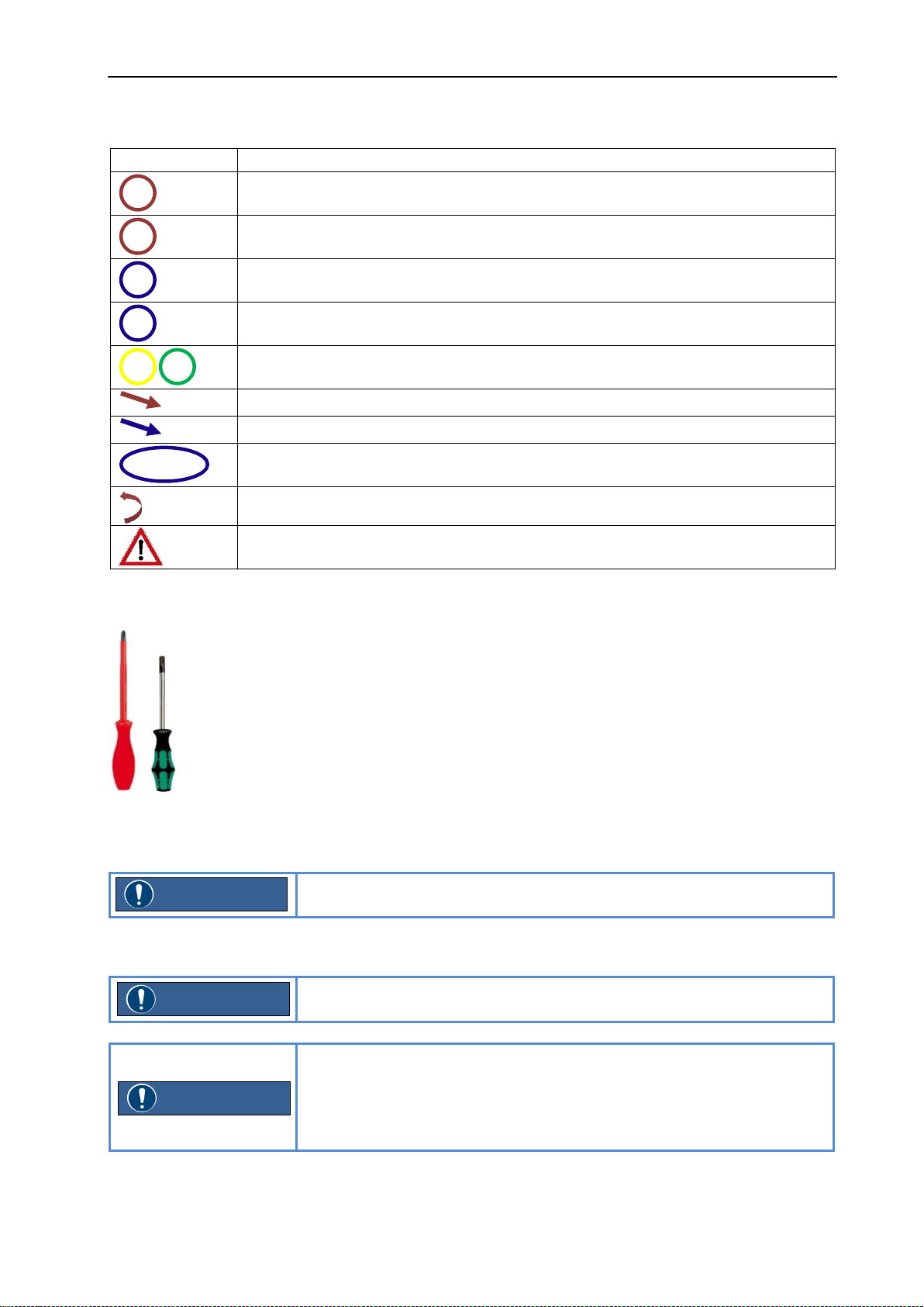
1 Legend
Symbol
Meaning
Component
Sub component
Process step
Process step, subordinate position
Order in which screws are tightened
Direction of movement or position
Process step, order, cut-out position (with or without arrow)
Cut-out, enlarged partial view
Turning movement, turning direction
Important note, must be complied with
2 Tools
1x Phillips screwdriver size 2
1x Torx wrench TX 30
Tools are not included in the delivery and must be supplied by
customer.
3 General information
If not otherwise specified, exchange of modules for devices x38 and
x98 is carried out in the same way.
If the device is installed, connected and in operation on site, the device
must first be taken out of operation.
Then all cable connections must be disconnected. Make sure that the
wires are de-energised !
Disassemble the device and all additional mounting parts !
1
1a
1
1a
13
1
NOTE
NOTE
NOTE

Module exchange - Step by step Installation Manual Module Exchange ET-/MT-xx8
R. STAHL HMI Systems GmbH / IM_Module_exchange_xx8_en_V_01_00_02.docx / 09.07.2020 Page 5 of 14
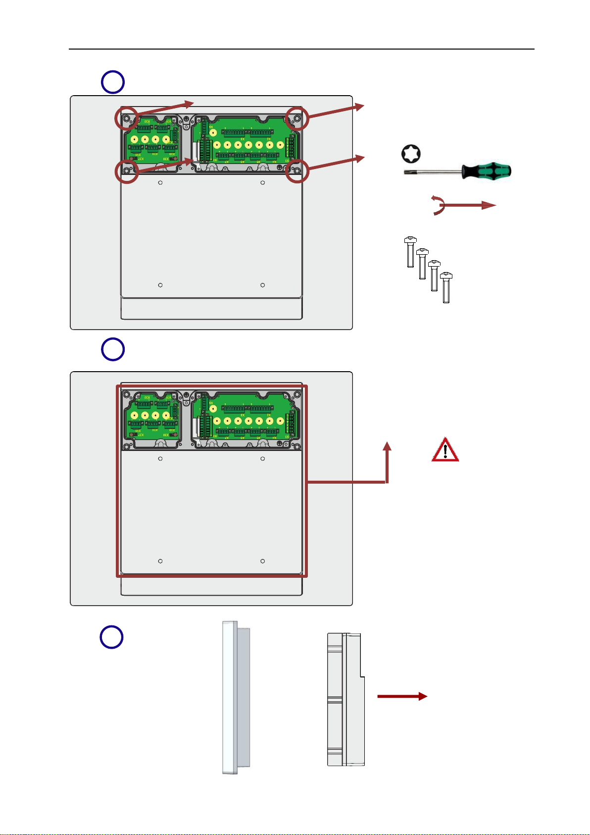
4 Module exchange - Step by step
4.1 VESA 200 Standard
4.1.1 Dismounting
8x
1
2
size 2
2x

Installation Manual Module Exchange ET-/MT-xx8 Module exchange - Step by step
Page 6 of 14 R. STAHL HMI Systems GmbH / IM_Module_exchange_xx8_en_V_01_00_02.docx / 09.07.2020
Lift in parallel
Display box
4x
3
4
E box
5
TX 30

Module exchange - Step by step Installation Manual Module Exchange ET-/MT-xx8
R. STAHL HMI Systems GmbH / IM_Module_exchange_xx8_en_V_01_00_02.docx / 09.07.2020 Page 7 of 14
4.1.2 Mounting
1a
4x
2
1
4x
E box
E box
Display box
Do not replace
in at an angle !
top
bottom
wrong
E box
Display box
Replace in
parallel !
top
bottom
4x
right

Installation Manual Module Exchange ET-/MT-xx8 Module exchange - Step by step
Page 8 of 14 R. STAHL HMI Systems GmbH / IM_Module_exchange_xx8_en_V_01_00_02.docx / 09.07.2020
3
4
5
2x
8x
size 2
6
push
4x
TX 30
tigthing torque: 10 Nm

Module exchange - Step by step Installation Manual Module Exchange ET-/MT-xx8
R. STAHL HMI Systems GmbH / IM_Module_exchange_xx8_en_V_01_00_02.docx / 09.07.2020 Page 9 of 14
4.2 VESA 200 Top Connect
4.2.1 Dismounting
Any accessories / connection kits must be removed / dismounted
before the E box is dismounted.
8x
1
2
size 2
NOTE
Installation Manual Module Exchange ET-/MT-xx8 Module exchange - Step by step
Page 10 of 14 R. STAHL HMI Systems GmbH / IM_Module_exchange_xx8_en_V_01_00_02.docx / 09.07.2020
Display box
4x
3
4
5
TX 30
Lift in parallel
E box

Module exchange - Step by step Installation Manual Module Exchange ET-/MT-xx8
R. STAHL HMI Systems GmbH / IM_Module_exchange_xx8_en_V_01_00_02.docx / 09.07.2020 Page 11 of 14
4.2.2 Mounting
1a
4x
2
3
1
4x
E box
push
E box
Display box
Do not replace
in at an angle !
top
bottom
wrong
E box
Display box
Replace in
parallel !
top
bottom
4x
right

Installation Manual Module Exchange ET-/MT-xx8 Module exchange - Step by step
Page 12 of 14 R. STAHL HMI Systems GmbH / IM_Module_exchange_xx8_en_V_01_00_02.docx / 09.07.2020
Any accessories / connection kits must be replaced after the E-box
has been replaced.
The installation instructions for the connection sets are
located in "IM_Top-Connect_xx8-*.pdf".
4
5
size 2
8x
6
NOTE
DOCUMENTATION
4x
TX 30
tigthing torque: 10 Nm

Release notes Installation Manual Module Exchange ET-/MT-xx8
R. STAHL HMI Systems GmbH / IM_Module_exchange_xx8_en_V_01_00_02.docx / 09.07.2020 Page 13 of 14
5 Release notes
The chapter entitled "Release Notes" contains all the changes made in every version of the
Instruction Manual.
Version 01.00.00
Section "Module exchange" included in this document as separate chapter
Module exchange for version VESA 200 Top Connect included
Correction of E-box illustration version VESA 200 Standard
Changing document name "IM_Connection-Kit_xx8" into "IM_Top-Connect_xx8"
Addition of headline with "Module Exchange"
Version 01.00.01
Deleting of label exchange
Text and formal changes
Version 01.00.02
Changing logo at cover
Changing HW-Rev at cover
Changing disclaimer, new mail addresses
Adaption address field verso
Addition of second note at "General information"
Addition of drawings "replace in at an angle" at standard and Top Connect
Formale changes

R. STAHL HMI Systems GmbH
Adolf-Grimme-Allee 8
D 50829 Köln
T: (Sales Support) +49 221 768 06 - 1000
(Technical Support) +49 221 768 06 - 5000
F: +49 221 768 06 - 4100
E: (Sales Support) [email protected]om
r-stahl.com
exicom.de
Other manuals for ET 8 Series
1
This manual suits for next models
1
Table of contents
Popular Server manuals by other brands

SUNLUNE
SUNLUNE JASMINER X4 instruction manual

GIGA-BYTE TECHNOLOGY
GIGA-BYTE TECHNOLOGY AMD EPYC R183-Z92-AAD1 user manual

Nortel
Nortel Enterprise Edge 2.0 Messaging Programming guide

Intel
Intel SR870BN4 - Server Platform - 0 MB RAM Product guide

Gateway
Gateway 9515 user guide

Dell
Dell PowerEdge 2800 Conversion guideline


