Stahl MANTA 400 Series User manual

Operating Instructions
Device platform MANTA
ET-xx7
SERIES 400 Panel PC
SERIES 500 Thin Clients
SERIES 600 KVM Systems
Doc. No.: 6000076
HW-Rev. ET-6x7: 01.03.05
HW-Rev. ET-4x7-*-BT: 01.03.05
HW-Rev. ET-5x7-*-BT: 01.03.05
HW-Rev. ET-4x7-*-P2: 01.03.04
HW-Rev. ET-5x7-*-P2: 01.03.04
Operating Instructions version: 01.03.24
Issue date: 19.08.2022
Order number: 296926

Operating Instructions ET-xx7 Disclaimer
Page 2 of 84 R. STAHL HMI Systems GmbH / OI_ET_xx7_en_V_01_03_24.docx / 19.08.2022
Disclaimer
Publisher and copyright holder:
R. STAHL HMI Systems GmbH
Adolf-Grimme-Allee 8
D 50829 Köln
Telephone: (Sales Support) +49 221 768 06 - 1200
(Technical Support) - 5000
Fax: - 4200
E-mail: (Sales Support) sales.dehm@r-stahl.com
(Technical Support) support.dehm@r-stahl.com
All rights reserved.
This document may not be reproduced in whole or in part except with the written
consent of the publisher.
Subject to alterations.
Any warranty claims are limited to the right to demand amendments. Liability for any damage
that might result from the contents of these instructions or all other documentation is limited to
clear cases of premeditation.
We reserve the right to change our products and their specifications at any time, provided it is in
the interest of technical progress. The information in the current manual (online or on CD / DVD
/ USB stick) or in the operating instructions included in the delivery applies.
Trademarks
The terms and names used in this document are registered trademarks and / or products of the
companies in question.
Copyright © 2022 by R. STAHL HMI Systems GmbH. Subject to alterations

Specific markings Operating Instructions ET-xx7
R. STAHL HMI Systems GmbH / OI_ET_xx7_en_V_01_03_24.docx / 19.08.2022 Page 3 of 84
Specific markings
The markings in these operating instructions refer to specific features that must be noted.
In detail, these are:
This sign alerts users to hazards that will result in death or serious
injury if ignored !
This sign alerts users to hazards that may result in death or serious
injury if ignored !
This sign alerts users to hazards that may damage machinery or
equipment or result in injury if ignored !
Information highlighted by this symbol indicates measures for the
prevention of damage to machinery or equipment !
Information highlighted by this symbol indicates important
information of which particular note should be taken !
Information highlighted by this symbol (with and without
lettering) refers to a different chapter or section in this
manual or other documentation or a web-page !
Warnings
Caution !
In ambient temperatures exceeding +45 °C the surface of the devices may heat
up. Caution when touching !
Caution !
The laser diodes installed in our Exicom operator devices, media converters and
switches emit invisible laser radiation:
100Base-FX - 1300 nm
FO-MM / 1000Base-SX - 770 … 860 nm
FO-SM / 1000Base-LX - 1270 … 1355 nm
Acc. to EN 60825-1 the laser diode is classified as a class 1M laser / Do not view
directly with optical instruments. The viewing of the laser beam through certain
optical instruments (e.g. magnifying glasses, telescopes and microscopes) from a
distance of less than 100 mm may damage eyesight. (beam output at the
emitting diode (TD-A, TD-B) or the fiber optic end).
DANGER
WARNING
CAUTION
DOCUMENTATION
NOTICE
ATTENTION

Operating Instructions ET-xx7 Table of contents
Page 4 of 84 R. STAHL HMI Systems GmbH / OI_ET_xx7_en_V_01_03_24.docx / 19.08.2022
Table of contents
Description Page
Disclaimer 2
Specific markings 3
Warnings 3
Table of contents 4
1Preface 7
2Device function 7
2.1 Image sticking 7
2.2 Processor types 7
2.3 Activation pressure touchscreen 7
2.4 ET-4x7 (SERIES 400 Panel PC) 8
2.5 ET-5x7 (SERIES 500 Thin Clients) 8
2.6 ET-6x7 (SERIES 600 KVM Systems) 8
2.7 Overview hardware revision 8
3Type allocation 9
3.1 Type marking 9
4Technical data 10
4.1 Additionally for ET-4x7 (Panel PC) 12
4.1.1 All devices up to hardware revision 01.03.00 12
4.1.2 All devices starting from hardware revision 01.03.01 13
4.1.3 All devices starting from hardware revision 01.03.03 13
4.1.4 ET-477 devices starting from hardware revision 01.03.04 13
4.2 Additionally for ET-5x7 (Thin Clients) 13
4.2.1 All devices up to hardware revision 01.03.00 13
4.2.2 All devices starting from hardware revision 01.03.01 14
4.2.3 All devices starting from hardware revision 01.03.03 14
4.2.4 ET-577 devices starting from hardware revision 01.03.04 14
4.3 Resolution at ET-6x7 (KVM Systems) with DVI3 14
5Conformity to standards 15
5.1 CEC / NEC / CSA 16
5.2 Mounting inside enclosure 16
6Certificates 17
Europe (CE / ATEX) 17
International (IECEx) 17
Russia (EAC) 17
USA (NEC) 17
Canada (CEC) 17
India (PESO / CCE / BIS) 17
Korea (KCC / KCS) 17
China (CCC / CNEx) 17
Australia (RCM) 17
Marine / ship certification (DNV / GL) 17
6.1 FSB notification 18
7Marking 18
8Power supply 19

Table of contents Operating Instructions ET-xx7
R. STAHL HMI Systems GmbH / OI_ET_xx7_en_V_01_03_24.docx / 19.08.2022 Page 5 of 84
8.1 HMI devices 19
9Permitted maximum values 19
9.1 External, non-intrinsically safe circuits 19
9.2 External inherently safe optical interface 20
9.3 External intrinsically safe circuits 20
10 Type code 21
10.1 Standard 21
10.1.1 ET-4x7 (Panel PC) 21
10.1.2 ET-4x7-*-BT (Panel PC) 22
10.1.3 ET-477-*-P2 (Panel PC) 23
10.1.4 ET-5x7 (Thin Client) 24
10.1.5 ET-5x7-*-BT (Thin Client) 25
10.1.6 ET-577-*-P2 (Thin Client) 26
10.1.7 ET-6x7 KVM System 27
10.2 Type code representation for China 28
10.2.1 ET-xx7 (Panel PC / Thin Client) 28
10.2.2 ET-6x7 (KVM Systems) 29
11 Safety information 31
11.1 General Safety Information 31
11.2 Cautionary note 31
11.3 Installation safety information 31
11.3.1 Only for HMI devices with DVI3 33
11.3.2 HMI installation in enclosures with degree of protection "e" or "t" 33
11.3.3 Conditions of safe use according to CEC / NEC / CSA 34
11.3.4 Tightening torque 34
11.3.4.1 Terminals 34
11.3.4.2 Cable glands 34
11.4 Industrial Security 34
11.5 Safety information for operation 35
11.6 Special conditions 35
12 Assembly and disassembly 36
12.1 General information 36
12.2 Cut-out ET-xx7 36
12.3 Tightening torque 36
13 Operation 37
13.1 General information 37
13.2 Connections 37
14 General Information 40
14.1 Touch driver 40
14.2 ET-4x7 (Panel PC) and ET-5x7 (Thin Client) 40
14.2.1 Up to Windows 7 operating systems 40
14.2.1.1 Licensing issues 40
14.2.1.2 Note on Windows Embedded operating systems 40
14.2.2 Windows® 10 IoT Enterprise 2019 LTSC operating system 40
14.2.2.1 Recovery 41
14.2.2.2 Company-specific Windows installations 41
14.2.3 Initial start-up ET-4x7 (Panel PC) 41

Operating Instructions ET-xx7 Table of contents
Page 6 of 84 R. STAHL HMI Systems GmbH / OI_ET_xx7_en_V_01_03_24.docx / 19.08.2022
14.2.4 Recovery Stick 41
14.2.5 Back-up 41
14.2.6 Switching off / closing down 42
14.2.7 Data loss 42
14.3 Teaming function 42
15 Maintenance, overhaul 43
15.1 Damaged sealing 43
16 Troubleshooting 43
16.1 Repairs / hazardous substances 43
17 Disposal / Restricted substances 44
17.1 Declaration of substances and restricted substances 44
17.1.1 Declarable substance groups 44
17.1.2 RoHS directive 2011/65/EC 44
17.1.3 IMO Resolution MEPC.269(68) 45
18 Defective pixels 45
18.1 Terminology 45
18.2 Display specification ET-x77 46
19 Optical acceptance of surfaces 47
19.1 Optical acceptance glass 47
19.2 Optical acceptance printing 48
19.3 Optical acceptance, other surfaces 48
20 Control Drawing CEC / NEC / CSA 50
21 Mounting inside enclosure with ET-xx7 mounting-set 52
22 Declarations of conformity 54
22.1 EC 54
22.2 RCM 56
22.3 EAC 58
22.4 CCC 62
22.4.1 English version 62
22.4.2 Chinese version 71
23 Release notes 80

Preface Operating Instructions ET-xx7
R. STAHL HMI Systems GmbH / OI_ET_xx7_en_V_01_03_24.docx / 19.08.2022 Page 7 of 84
1 Preface
These Operating Instructions contain all aspects relevant to explosion protection for the ET-xx7
devices - device platform MANTA - (SERIES 400 Open HMI - Panel PC´s, SERIES 500 Thin
Clients and SERIES 600 KVM Systems). They also contain information on the connection and
installation (etc.) of these devices.
All data relevant to explosion protection from the EC-type
examination certificate were copied into these operating instructions.
For the correct operation of all associated components please note,
in addition to these operating instructions, all other operating
instructions enclosed in this delivery as well as the operating
instructions of the additional equipment to be connected !
Please note that all certificates of the HMI devices can be
found in a separate document (CE_ET-xx7).
You can find this document in the internet at
r-stahl.com or request it from R. STAHL HMI Systems
GmbH.
2 Device function
The ET-xx7 units are explosion-protected equipment for installation in hazardous areas and can
be operated in zones 1 and 21 with interfaces for zones 0/1/2 and 20/21/22.
The devices are connected to a communication system via the serial interfaces (RS-232,
Ethernet) located in their connection box at the rear. The connection box also contains the USB
interfaces for the connection of various peripheral devices. Furthermore, the interfaces for
keyboard, mouse, video and audio signals are also located here.
2.1 Image sticking
Continuous displaying fixed pattern may include image sticking. It’s recommended to use
screen saver or moving content periodically if fixed pattern is displayed on the screen.
2.2 Processor types
All devices of 400 and 500 SERIES are fitted with modern, powerful processors. Depending on
the type of application, different processor types are used for the HMI devices (see Technical
Data).
Starting in 2016, a new Intel® ATOM™ processor type of the Bay Trail (BT) platform will
gradually replace all previous processor types in the HMI devices, up from HW Revision
01.03.01. This new processor type processes data four times as fast as the previous
processors.
In addition to the Bay Trail (BT) processor, the devices of 400 and 500 SERIES will be equipped
with an AMD GX processor, up from HW Revision 01.03.04.
2.3 Activation pressure touchscreen
To prevent damage to the touchscreen, activation pressure on the screen with polyester foil
must be very low (0.1 to max. 1 N) and on the screen with glass surface must be medium (1.8 to
max. 2.5 N) !
NOTICE
DOCUMENTATION

Operating Instructions ET-xx7 Device function
Page 8 of 84 R. STAHL HMI Systems GmbH / OI_ET_xx7_en_V_01_03_24.docx / 19.08.2022
2.4 ET-4x7 (SERIES 400 Panel PC)
The ET-4x7 HMI panel PCs are intelligent display and operating devices which can run any
software and are thus easy to operate.
The devices are fitted with powerful processors and are thus able to process even large
applications on-site. The devices have a back-up and recovery system which can be used to
save complete images and load them onto new Panel PCs without requiring specific IT skills.
The X13 interface is provided for this purpose.
2.5 ET-5x7 (SERIES 500 Thin Clients)
The ET-5x7 devices of the 500 SERIES can be integrated into modern networks as Thin Clients
or with a KVM box via KVM-over-IP. Digital Ethernet technology is used for the data transfer
between KVM box and Remote System.
Up to four ET-5x7 devices can access one KVM box with one software license, thus cost-
effectively communicating with several PCs - for example, when monitoring the production
process and simultaneously applying Condition Monitoring.
Multi-monitoring with several on-site terminals can as easily be implemented as the application
as Thin Client in a server environment with virtual work stations.
2.6 ET-6x7 (SERIES 600 KVM Systems)
The KVM Classic transfer technology is used for the point-to-point connection between a PC
and an ET-6x7 KVM device.
There are three versions (DVI1, DVI2 and DVI3) of this transfer technology that have slightly
different functionality.
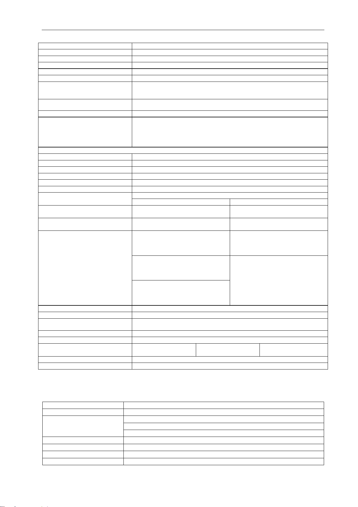
2.7 Overview hardware revision
HW-Rev.
Device type
Technical changing
Changing date
hardware
OI
version
OI date
01.02.00
ET-xx7-*
Changing from T-Ex
to ET-xx7
01.01.2013
01.02.00
17.04.2013
01.03.00
ET-xx7-*
NEC / CEC approval
12.12.2014
01.03.00
08.01.2015
01.03.01
ET-4x7-*-BT-*
ET-5x7-*-BT-*
Bay Trail processor,
quad core
01.07.2016
01.03.02
04.01.2016
01.03.02
ET-4x7-*-BT-*
ET-5x7-*-BT-*
SX with TX
15.01.2018
01.03.09
21.12.2017
01.03.03
ET-4x7-*-BT-*
ET-5x7-*-BT-*
M.2 memory
14.06.2018
01.03.11
29.08.2018
01.03.04
ET-4x7-*-P2-*
ET-5x7-*-P2-*
AMD processor
GX-222GC
31.03.2019
01.02.05
ET-4x7-*-BT-*
ET-5x7-*-BT-*
BIOS update
BIOS-V1.63r4 no C6
29.06.2021
01.03.21
27.09.2021
ET-4x7-*-BT-*
ET-5x7-*-BT-*
ET-6x7-*
Changing cable
glands

Type allocation Operating Instructions ET-xx7
R. STAHL HMI Systems GmbH / OI_ET_xx7_en_V_01_03_24.docx / 19.08.2022 Page 9 of 84
3 Type allocation
Since the beginning of 2013, the T-series devices have been allocated new type names
according to the following pattern:
To avoid having to re-write certifications, the names in the certificates remain the same, but the
devices receive new names.
In the interest of a clear link between device type and certificate, both device names are listed
on the type plate from 01.04.2013 onwards.
3.1 Type marking
Old (certificate)
New
T-Ex-##*-CAT7*-R2
ET-##7*-TX* / ET-##7-2TX*
T-Ex-##*-CAT7*-R2
ET-##7*-CAT*
T-Ex-##*-MM*-R2
ET-##7*-MM* / ET-##7-SX*
T-Ex-##*-SM*-R2
ET-##7*-SM* / ET-##7-LX*
* = alphanumeric or symbolic characters without relevance to explosion protection.
# = numeric character without relevance to explosion protection.
For the exact new device name and model please refer to the type
code.
NOTICE

Operating Instructions ET-xx7 Technical data
Page 10 of 84 R. STAHL HMI Systems GmbH / OI_ET_xx7_en_V_01_03_24.docx / 19.08.2022
4 Technical data
Function / Equipment
ET-467
ET-567
ET-667
ET-477
ET-577
ET-677
ET-487
ET-587
ET-687
Display type
TFT Color display
16.7 million colours
Display size
56 cm (22")
61 cm (24")
61 cm (24"WU)
Resolution in pixels
WSXGA+ 1680 x 1050
Full HD 1920 x 1080
WUXGA 1920 x 1200
Format
16:10
16:9
16:10
Viewing angle
at CR ≥ 5
at CR ≥ 5
at CR ≥ 10
Horizontal
178°
178°
178°
Vertical
170°
170°
178°
Display
Glass
Touchscreen (optional)
Polyester foil or glass surface
5-wire analogue resistive
Backlight
LED background lighting
Service life (MTBF) of backlight at
20 °C / 68 °F
Typically 50,000 h
Brightness
250 cd/m²
300 cd/m²
Contrast
1000 : 1
Anti-reflective display
Devices without touchscreen: chemically coated
Devices with foil touchscreen: lightly anti-reflective (foil is abraded for slight milky effect)
Device with glass touchscreen: not anti-reflective, glass is too thin for chemical or
mechanical treatment
Touchscreen activation
Foil touch: low activation pressure (0.1 up to max. 1 N)
Glass touch: medium activation pressure (1.8 up to max. 2.5 N)
Touchscreen input method
Finger, gloved finger or stylus
Touchscreen durability
Foil touch: Polyester foil is easily scratched, with high pressure force the spacer dots
could be damaged.
Glass touch: Quite good, but with high pressure force the spacer dots could be damaged.
Touchscreen scratch hardness MoHS
Foil touch: -
Glass touch: >5
Touchscreen scratch hardness pencil
hardness test ISO 15184
Foil touch: 3H
Glass touch: 9H
Touchscreen transmissivity / optics
Foil touch: small milky effect due to the foil
Glass touch: very good
Touchscreen surface contaminants
Unaffected
Touchscreen abrasive resistance
36 million times with a silicone rubber of R8 finger, hitting rate 250 g at 2 times per second
Additional keyboard (optional)
107 keys with integrated trackball / joystick / mouse pad or touch pad
Power supply
Directly in the integrated Ex e connection box
Rated operational voltage AC
230 V
Voltage range AC
100 - 240 V
Frequency range
50 - 60 Hz
Rated operational voltage DC
24 V
Voltage range DC
20 - 30 V
Power
Typically 50 W / 100 W at O30 / max. 150 W
(typically 170 BTU / 341 BTU at O30 / max. 510 BTU)
Current consumption AC
1 A
Current consumption DC
3 A
Connections
via screw terminals, green
Flexible cable up to 2.5 mm² (AWG14)
Fixed cable up to 4 mm² (AWG12)
Recommended fuses
4 AT
Max. operating voltage Um
250 VAC

Technical data Operating Instructions ET-xx7
R. STAHL HMI Systems GmbH / OI_ET_xx7_en_V_01_03_24.docx / 19.08.2022 Page 11 of 84
Interfaces
Ethernet
Either copper or optical fiber *
at ET-4x7 and ET-5x7
for information on copper, see sections 4.1 and 4.2
Optical fiber (SX)
1000Base-SX, 1000 Mbit, multi-mode, intrinsically safe (Ex op is)
Optical fiber (LX)
1000Base-LX, 1000 Mbit, single mode, intrinsically safe (Ex op is)
* Note optical fiber (SX and
LX)
Up from HW-Rev. 01.03.02, all ET-4x7 and ET-5x7 devices with SX or LX Ethernet interface
are fitted additional with an Ethernet 10/100/1000Base-TX interface !
at ET-6x7
Copper (CAT)
Direct connection, Gigabit
Optical fiber (FO) (MM / SM)
Direct connection
USB
2x Ex ia; 1x Ex e / USB 2.0, 480 Mbit/s
USB
for keyboard and mouse (Ex ia) / USB 2.0, 480 Mbit/s
Note on USB interfaces
The USB interfaces are based on USB 2.0. Due to explosion protection rules, the USB
interface properties (such as speed or power supply) may be restricted.
Serial
RS-232, (Ex e)
Video in (optional)
FBAS (Ex e) (not AMD version)
Audio
Line out interface (Ex e) (Line in only at ET-6x7)
Audio sound (optional)
Audio amplifier (mono amplifier) 3.5 W, for 2x loudspeaker connection (Ex e)
(not AMD version)
Voltage output
12 VDC, max. 500 mA **
** Note
The voltage output has an internal fuse that cannot be replaced !
Only for ET-4x7 and ET-5x7
Real-time clock
yes
Data buffer
Lithium battery and capacitor buffered, maintenance-free
Battery
> 5 years
Capacitor
at least 4 days
Cable type optical fiber
SX or MM
LX or SM
Multi-mode optical fiber cable (50 µm core cross section and 125 µm external cross section)
Multi-mode optical fiber cable (62.5 µm core cross section and 125 µm external cross section)
Single mode optical fiber cable (9 µm core cross section and 125 µm external cross section)
Data cable lengths
Optical fiber
SX or MM
up to 550 m (1,804 ft) via 50/125 μm optical fiber cable
up to 275 m (902 ft) via 62.5/125 μm optical fiber cable
LX or SM
up to 10,000 m (33,000 ft) via 9/125 μm optical fiber cable
Copper (TX)
up to 100 m (330 ft) via CAT7 installation cable AWG23 at 1x TX
2x up to 100 m (330 ft) via CAT7 installation cable AWG23 at 2TX
Copper (CAT)
for DVI1
up to 140 m (460 ft) via CAT7 installation cable AWG23
for DVI2
up to 500 m (1,640 ft) via CAT7 installation cable AWG23
for DVI3
up to 150 m (492 ft) via CAT7 installation cable AWG23
Note CAT cable
Minimum requirement is CAT5e, CAT7 recommended
Enclosure
Steel
Enclosure protection type
Front IP66 / back IP65
HMI Types
PM = PanelMount = panel mount device
OS = Operator Station
HMI Types comment
Panel mount device (PM): devices without additional enclosure (HSG) and without additional
accessories
Operator Station (OS): devices mounted inside additional enclosure (HSG)
Cable glands
Type *
HSK-M-Ex (Ex e)
Number
2 x M16 / 1 x M20 / 3 x M25
Thread size
M16 x 1.5 / M20 x 1.5 / M25 x 1.5
Cable diameter range
1x M16 = 4 … 8 mm / 1x M16 = 5 … 10 mm / M20 = 7 … 13 mm / M25 = 14 … 18 mm
Width across flats
M16 = SW20 / M20 = SW24 / M25 = SW30
Mounting version keyboards
when wiring KBDi-USB, use the cable glands 2x M16 4… 8 mm
(1x enclosed loose, exchange it for 1x M16 5… 10 mm)
when wiring KB2, use the cable gland 1x M16 5… 10 mm (is pre-assembled)
* Comment
Similar certified cable glands may be used.
* Comment a
Not used cable glands must be closed by certified screw plugs or stopping plugs !
Operating Instructions ET-xx7 Technical data
Page 12 of 84 R. STAHL HMI Systems GmbH / OI_ET_xx7_en_V_01_03_24.docx / 19.08.2022
Permitted ambient temperature range
-30 °C … +60 °C / [-22 °F … +140 °F]
Operating temperature range
Cold start temperature *
-10 °C / [+14 °F]
Operation **
-20 °C … +60 °C / [-4 °F … +140 °F]
Operation with heater version O30 ***
-30 °C … +60 °C / [-22 °F … +140 °F]
Storage temperature range
-30 °C … +70 °C / [-22 °F … +158 °F]
* Note on cold start temperature
If the device is switched on in an ambient temperature of below -10 °C / [+14 °F], the
display will require some time warming up before everything is clearly visible. Depending
on how low the actual temperature is, this process may take up to 3 hours.
** Note on operation
Operation at +60 °C / [+140 °F] for a maximum of 5 hours,
at +50 °C / [+122 °F] for continuous operation (24/7)
*** Note on the O30 version
The O30 version is only available for the AC version devices ! (not AMD version)
HMI Types comment OS
If the HMI device is installed in an additional enclosure (HSG), the upper temperature limit
is reduced by 5 °C / [41 °F], due to the device's own heating and lower
temperature dissipation in the additional enclosure !
Thus, the operator stations offers "only" an operation temperature range of
-20 °C …+55 °C / [-4 °F … +131 °F] !
Operating temperature range for DVI1
Cold start temperature
+5 °C [+41 °F]
Operation
+5 °C … +40 °C / [+41 °F … +104 °F]
Storage temperature range
-20 °C … +70 °C / [-4 °F … +158 °F]
Heat dissipation
About 40 % via the front plate and 60 % via the enclosure
Relative humidity
10 to 90 % at +40 °C / [+104 °F], non-condensing
for DVI1
20 to 80 % at +40 °C / [+104 °F], non-condensing
Environmental conditions
Valid for all devices
Level
Test specification
Damp heat (cyclic)
(only device with glass touch (TG))
+55 °C (±2 °C) ≥95 %
IEC 60068-2-30 : 2005
Dry heat
+65 °C
IEC 60068-2-2 : 2007
IEC 60068-2-78 : 2012
Vibration (sinus)
5 up to 13.2 Hz: ±1 mm
13.2 up to 100 Hz: ±0.7 g
Sweep cycle 1 oct/min
Axis X, Y, Z
IEC 60068-2-6 : 2008
71.7 up to 79.2 Hz: ±0.7 g
120 min.
Sweep cycle 1 oct/min
Axis X
IEC 60068-2-6 : 2008
Dwell test
30 Hz: ±0.7 g
90 min.
Sweep cycle 1 oct/min
Axis Y, Z
Dimensions
Front (w x h)
660 mm x 475 mm (25.98” x 18.70”)
Cut-out
(w x h) (+/-0.5 mm) (0.002")
615 mm x 435 mm (24.21” x 17.13”)
Depth of cut-out
110 mm (4.33")
Wall thickness
≤5 mm (0.02")
Cut-out dimension for rear mount module
(w x h)
475.7 mm x 298.1 mm
523 mm x 295 mm
520.4 mm x 326 mm
(18.73" x 11.74")
(20.59" x 11.61")
(20.49" x 12.83")
Mounting position
Vertical or horizontal
Weight
32.00 kg (70.55 lbs)
4.1 Additionally for ET-4x7 (Panel PC)
4.1.1 All devices up to hardware revision 01.03.00
Processor
Intel ATOM N270; 1.6 GHz
RAM
1 or 2 GB
Data memory
4 or 16 GB
128 GB MLC
128 GB SLC
Type of data memory
Flash memory (SATA)
Operating system
Windows XP Embedded / Windows XP Professional / Windows 7 Ultimate (32 bit)
Global language support
Via Multi-Language interface of Windows XP Embedded (25 languages)
Interface copper (TX)
1x 10/100Base-TX, 10/100 Mbit (Ex e)

Technical data Operating Instructions ET-xx7
R. STAHL HMI Systems GmbH / OI_ET_xx7_en_V_01_03_24.docx / 19.08.2022 Page 13 of 84
4.1.2 All devices starting from hardware revision 01.03.01
Processor
Intel Bay Trail (BT) ATOM E3845 Quad Core; 1.91 GHz
RAM
4 GB
Data memory
Size
TBW
Test profile
64 GB MLC
18.75
JESD218 Client profile
128 GB MLC
37.5
Type of data memory
Flash memory (Solid state drive - SSD) (internal via CF-Slot)
Graphics controller
Integrated Intel Gen. 7 HD Graphics
Operating system
Windows Embedded Standard 7 (64 bit) / Windows 7 Ultimate (64 bit)
Global language support
Via Windows operating system
Interface copper (TX)
1x 10/100Base-TX, 10/100 Mbit (Ex e)
or
2x 10/100Base-TX, 10/100 Mbit (Ex e)
Note copper
If the customer installs an operation system, the driver for the "USB-SK-LAN-Adapter" must
(Driver is part of STAHL images)
4.1.3 All devices starting from hardware revision 01.03.03
Type of data memory
Flash memory M.2 (Solid State Drive - SSD) (internal via SATA)
Operating system
Windows 10 IoT Enterprise (64 bit) (included in standard delivery)
Windows 10 IoT Enterprise (32 bit) (optional on USB stick)
4.1.4 ET-477 devices starting from hardware revision 01.03.04
Processor type
AMD GX-222GC
Processor details
2.2 GHz; Dual Core, 10W TDP
Graphics controller
integrated AMD Radeon R5E graphics
Interface copper (TX)
1x 10/100Base-TX, 10/100 Mbit (Ex e)
or
2x 10/100Base-TX, 10/100 Mbit (Ex e)
4.2 Additionally for ET-5x7 (Thin Clients)
4.2.1 All devices up to hardware revision 01.03.00
Processor
AMD Geode LX 800; 266 MHz
RAM
512 MB
2 GB *
Data memory
1 GB
16 GB *
Operating system
Windows Embedded Standard 2009 and Remote Firmware
Windows Embedded Standard 7, Remote Firmware and Delta V *
Interface copper (TX)
1x 10/100Base-TX, 10/100 Mbit (Ex e)
* The combination of 2 GB RAM with 16 GB data memory is only
available for the operating system with Delta V !
NOTICE
Operating Instructions ET-xx7 Technical data
Page 14 of 84 R. STAHL HMI Systems GmbH / OI_ET_xx7_en_V_01_03_24.docx / 19.08.2022
4.2.2 All devices starting from hardware revision 01.03.01
Processor
Intel Bay Trail (BT) ATOM E3845 Quad Core; 1,91 GHz
RAM
4 GB
Data memory
Size
TBW
Test profile
64 GB MLC
18.75
JESD218 Client profile
128 GB MLC
37.5
Type of data memory
Flash memory (SATA)
Graphics controller
Integrated Intel Gen. 7 HD Graphics
Operating system
Windows 10 IoT Enterprise and Remote Firmware
Interface copper (TX)
1x 10/100Base-TX, 10/100 Mbit (Ex e)
or
2x 10/100Base-TX, 10/100 Mbit (Ex e)
Note copper
If the customer installs an operation system, the driver for the "USB-SK-LAN-Adapter" must
(Driver is part of STAHL images)
4.2.3 All devices starting from hardware revision 01.03.03
Type of data memory
Flash memory M.2 (Solid State Drive - SSD) (internal via SATA)
4.2.4 ET-577 devices starting from hardware revision 01.03.04
Processor type
AMD GX-222GC
Processor details
2.2 GHz; Dual Core, 10W TDP
Graphics controller
integrated AMD Radeon R5E graphics
Interface copper (TX)
1x 10/100Base-TX, 10/100 Mbit (Ex e)
or
2x 10/100Base-TX, 10/100 Mbit (Ex e)
4.3 Resolution at ET-6x7 (KVM Systems) with DVI3
Function / Equipment
ET-667
ET-677
ET-687
Resolution in pixels
1680 x 1050
1920 x 1080
1920 x 1200
1280 x 1024
1600 x 1200
1920 x 1080
1280 x 960
1600 x 1000
1680 x 1050
1152 x 864
1400 x 1050
1600 x 1200
1024 x 768
1360 x 768
1280 x 1024
800 x 600
1280 x 1024
1280 x 960
1280 x 920
1280 x 800
1280 x 800
1152 x 864
1152 x 864
1024 x 768
1024 x 768
800 x 600
800 x 600

Conformity to standards Operating Instructions ET-xx7
R. STAHL HMI Systems GmbH / OI_ET_xx7_en_V_01_03_24.docx / 19.08.2022 Page 15 of 84
5 Conformity to standards
The ET-xx7 devices comply with the following standards and directive:
Standard
Classification
2. Supplement
ATEX directive 2014/34/EU
EN 60079-0 : 2009
General requirements
EN 60079-5 : 2007
Powder filling "q"
EN 60079-7 : 2007
Increased safety "e"
EN 60079-11 : 2007
Intrinsic safety "i"
EN 60079-26 : 2007
Device protection (EPL) "Ga"
EN 60079-28 : 2004
Optical radiation
EN 60079-31 : 2009
Protected by enclosures "tD" (dust)
EN 61241-11 : 2006
Intrinsic safety "iD" (dust)
The product corresponds to requirements from:
EN 60079-0 : 2012 + A11 : 2013
General requirements
EN IEC 60079-0 : 2018
EN 60079-5 : 2015
Powder filling "q"
EN 60079-7 : 2015
Increased safety "e"
EN IEC 60079-7 : 2015 + A1 : 2018
EN 60079-11 : 2012
Intrinsic safety "i"
EN 60079-26 : 2015
Device protection (EPL) "Ga"
EN 60079-28 : 2016
Optical radiation
EN 60079-31 : 2014
Protected by enclosures "tD" (dust)
Electromagnetic compatibility
EMC directive
2014/30/EU
Classification
EN 61000-6-2 : 2005
Interference resistance
EN 61000-6-4 : 2007 + A1 : 2011
Interference emission
Low voltage directive
Directive 2014/35/EU
EN 61010-1 : 2001+
General requirements
EN 62368-1 : 2016
IEC 62368-1 : 2014
Audio / video, information and communication
technology equipment - Safety requirements
RoHS directive
2011/65/EU
Classification
EN IEC 63000 : 2018
Technical documentation for the assessment
of electrical and electronic products with
respect to the restriction of hazardous
substances

Operating Instructions ET-xx7 Conformity to standards
Page 16 of 84 R. STAHL HMI Systems GmbH / OI_ET_xx7_en_V_01_03_24.docx / 19.08.2022
5.1 CEC / NEC / CSA
Standard
Classification
CAN/CSA-C22.2 No. 0-10
August 2011
General requirements
Canadian Electrical Code, Part II
CAN/CSA-C22.2 No. 61010-1-12
Safety Requirements for Electrical Equipment
for Measurement, Control, and Laboratory
Use - Part 1: General Requirements
(Third Edition)
CAN/CSA-C22.2 No. 60079-0 : 11
(December 2011)
Explosive atmospheres –Part 0: Equipment
General requirements
CAN/CSA-C22.2 No. 60079-5 : 11
(December 2011)
Explosive atmospheres –Part 5: Equipment
protection by powder filling “q”
CAN/CSA-C22.2 No. 60079-7 : 12
(February 2012)
Explosive atmospheres –Part 7: Equipment
protection by increased safety “e”
CAN/CSA-C22.2 No. 60079-11 : 11
(December 2011)
Explosive atmospheres –Part 11: Equipment
protection by intrinsic safety “i”
CAN/CSA-C22.2 No. 60529:05
(Reaffirmed 2010)
Degrees of protection provided by enclosures
(IP Code)
ANSI/UL 61010-1
(2012)
Electrical Equipment for Measurement,
Control, and Laboratory Use - Part 1: General
Requirements (Third Edition)
ANSI/UL 60079-0
(sixth edition July 2013)
Explosive atmospheres –
Part 0: Equipment –General requirements
ANSI/UL 60079-5
(third edition November 2013)
Explosive atmospheres –
Part 5: Equipment protection by
powder filling “q”
ANSI/UL 60079-7
(fourth edition May 2013)
Explosive atmospheres –
Part 7: Equipment protection by
increased safety “e”
ANSI/UL 60079-11
(sixth edition March 2014)
Explosive atmospheres –
Part 11: Equipment protection by
intrinsic safety “i”
ANSI/IEC 60529-2004
Degrees of protection provided by enclosures
(IP code)
5.2 Mounting inside enclosure
The ET-xx7 devices can be mounted in an enclosure with suitable cut-out using an mounting kit.
This mounting kit is approved for mounting in an Ex e, Ex p or Ex tb protected enclosure and
consist of a sealing fixed at the HMI device and 24 nuts.
The assembly is shown in drawing “10410300 T-Ex - xx7 Mounting Assembly Overview”.
The sealing must be in correct position and must not be damaged.
The nuts must be mounted with a torque of 1.0 Nm ... 1.4 Nm.

Certificates Operating Instructions ET-xx7
R. STAHL HMI Systems GmbH / OI_ET_xx7_en_V_01_03_24.docx / 19.08.2022 Page 17 of 84
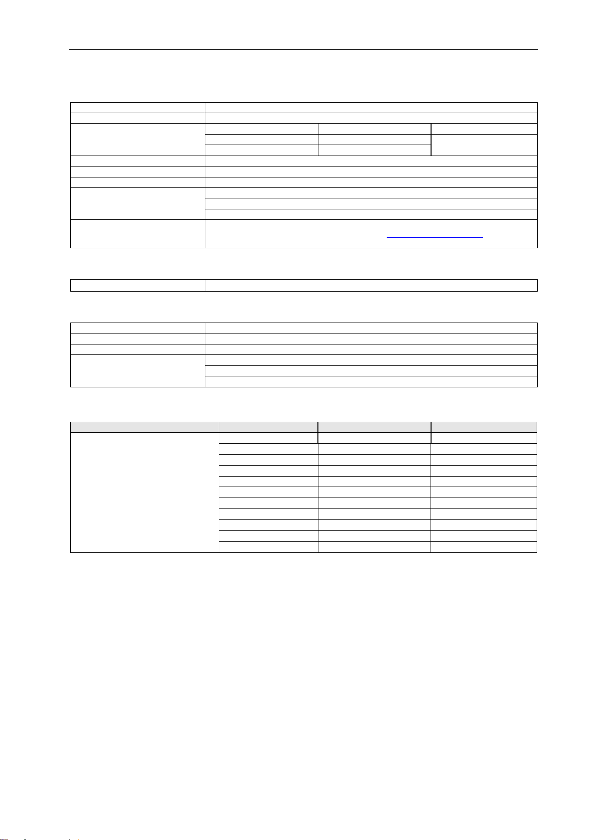
6 Certificates
The ET-xx7 devices are certified for installation in the following areas:
Synonym
Scope
Certificate number
Valid until
Comment
CE / ATEX
Europe
BVS 11 ATEX E 102 X
unlimited
IECEx
Global
IECEx BVS 11.0075X
unlimited
EAC
Russia
TC RU C-DE.HA91.B.00166/20
11.08.2025
NEC
USA
CSA 70011698
unlimited
CEC
Canada
see notice CEC
PESO
India
A/P/HQ/TN/104/5768 (P438244)
31.12.2023
CCE
P438244/1
Identification number
BIS
R-41228087
26.06.2024
only ET-577-* devices
KCC
Korea
unlimited
Device restriction see
notice KCC
KCS
12-GA4BO-0617X
unlimited
CCC
China
2021312309000500
08.06.2026
CNEX
CNEx21.1938X
16.06.2026
RCM
Australia
unlimited
According to declaration
of conformity
DNV / GL
Marine- / ship
certification
TAA00000BK
01.12.2026
Device restriction see
notice DNV / GL
You can access all IECEx certificates on the official
website of the IEC under their certificate number.
https://www.iecex-certs.com/#/home.
Note CEC:
The HMIs are certified according to Ex e q [ia] IIC T4 Gb.
According to the CEC Part 1 each device with these protection types
may be operated in Class I, Division 2 areas.
For more details on this, please refer to the CEC.
Note KCC:
In order to be able to operate these HMI devices in Korea, each
device type additionally requires a KCC certificate.
Actually the following devices has such a certificate:
T-Ex-22 (ET-x67), T-Ex-22-DVI3 (ET-667-DVI3), T-Ex-24T (ET-x77
with touch screen (foil))
The importer have to use exception documents which are applied in
Korea rule for Korea.
A corresponding example document, the so-called "Customer
confirmation letter", is included in the CE_ET-xx7 certificate
compilation of the devices.
NOTICE
DOCUMENTATION
NOTICE

Operating Instructions ET-xx7 Marking
Page 18 of 84 R. STAHL HMI Systems GmbH / OI_ET_xx7_en_V_01_03_24.docx / 19.08.2022
Note DNV / GL:
Only the HMI devices type:
ET-667-DVI3-yM-FO-TFT-TG-AC-O30-AL
ET-677-DVI3-yM-FO-TFT-TG-AC-O30-AL
ET-687-DVI3-yM-FO-TFT-TG-AC-O30-AL
have DNV / GL certification!
with y: M = FO direct connection multi-mode
S = FO direct connection single mode
6.1 FSB notification
The FSB notification of the MANTA field systems can be reviewed under this link:
https://portal.eaeunion.org/sites/odata/_layouts/15/Portal.EEC.Registry.Ui/DirectoryForm.aspx?ViewId=859e
c98d-f4fe-423a-b6bc-d01b53fd4b7c&ListId=0e3ead06-5475-466a-a340-
6f69c01b5687&ItemId=232#f=STAHL
7 Marking
Manufacturer
R. STAHL HMI Systems GmbH
Type code
ET-4x7 / ET-5x7 / ET-6x7
CE classification:
c0158
Testing authority and certificate
number:
BVS 11 ATEX E 102 X
Ex classification:
ATEX
e
II 2(1) G Ex eb q [ia op is Ga] IIC T4 Gb
II 2(1) D Ex tb IIIC [ia op is Da] IP65 T110°C Db
IECEx
Ex eb q [ia op is Ga] IIC T4 Gb
Ex tb IIIC [ia op is Da] IP65 T110°C Db
EAC
1Ex e q [ia op is Ga] IIC T4 Gb X
Ex tb IIIC [ia op is Da] T110°C Db X
NEC
Class I, Zone 1 AEx e q [ia] IIC T4 Gb
Class I, Division 2, Groups A, B, C, D
(according to NEC 501.5)
CEC
Ex e q [ia] IIC T4 Gb
Class I, Division 2, Groups A, B, C, D
(according to CEC J18-150)
PESO
Ex eb q [ia op is Ga] IIC T4 Gb
KCS
Ex e q IIC T4
Ex tb IIIC IP64 T110°C
Ex ia IIC T4
Ex ia IIIB T110°C
CCC / CNEX
Ex e q [ia op is Ga] IIC T4 Gb
Ex tD [iaD op is] A21 IP65 T110°C
NOTICE

Power supply Operating Instructions ET-xx7
R. STAHL HMI Systems GmbH / OI_ET_xx7_en_V_01_03_24.docx / 19.08.2022 Page 19 of 84
8 Power supply
8.1 HMI devices
Power supply: 24 VDC or 100 –240 VAC, 50 –60 Hz
max. power consumption: at 24 VDC max. 3 A
at 100 - 240 VAC max. 1 A
9 Permitted maximum values
9.1 External, non-intrinsically safe circuits
Input voltage “PWR” (X10):
Nominal voltage: 20 ...240 VAC/VDC (depending on type)
Power consumption Imax ≤5 A
Power Pmax ≤150 W
Max. operating voltage Um≤ 250 VAC
Short-circuit current IK≤ 1500 A
USB (X13):
Rated voltage 5 VAC/VDC (±10 %)
Max. operating voltage Um≤ 250 VAC
12 V (X14):
Rated voltage 12 VAC/VDC (±10 %)
Power consumption Imax ≤ 400 mA
Max. operating voltage Um≤ 250 VAC
RS-232 "SER" (X97):
Rated voltage 15 VAC/VDC (±10 %)
Max. operating voltage Um≤ 250 VAC
Video "CAM" (X101):
Rated voltage 5 VAC/VDC (±10 %)
Max. operating voltage Um≤ 250 VAC
Audio "AUD" (X105):
Rated voltage 100 VAC/VDC (±10 %)
Max. operating voltage Um≤ 250 VAC
Copper Ethernet (CAT7 1) (X16):
Rated voltage 5 VAC/VDC (±10 %)
Max. operating voltage Um≤ 250 VAC

Operating Instructions ET-xx7 Permitted maximum values
Page 20 of 84 R. STAHL HMI Systems GmbH / OI_ET_xx7_en_V_01_03_24.docx / 19.08.2022
9.2 External inherently safe optical interface
Ethernet optical fiber (FO 1) (X18)
Multi-mode
Wavelength 850 nm
Radiant power 0.22 mW
max. radiant power: 35 mW
Single mode
Wavelength 1310 nm
Radiant power 0.22 mW
max. radiant power: 35 mW
9.3 External intrinsically safe circuits
Keyboard (X11)
The maximum values are:
Ui
=
5.5
V
Uo
=
5.5
V
Ii
=
3
A
lo
=
309
mA
Pi
=
2
W
Po
=
629
mW
Ci
=
negligible
µF
Co
=
50
µF
Li
=
negligible
mH
Lo
=
40
µH
Pointer device (X12):
The maximum values are:
Ui
=
5.5
V
Uo
=
5.5
V
Ii
=
3
A
lo
=
309
mA
Pi
=
2
W
Po
=
629
mW
Ci
=
negligible
µF
Co
=
50
µF
Li
=
negligible
mH
Lo
=
40
µH
USB1i (X24):
The maximum values are:
Ui
=
5.5
V
Uo
=
5.5
V
Ii
=
3
A
lo
=
309
mA
Pi
=
2
W
Po
=
629
mW
Ci
=
negligible
µF
Co
=
50
µF
Li
=
negligible
mH
Lo
=
40
µH
USB2i (X25):
The maximum values are:
Ui
=
5.5
V
Uo
=
5.5
V
Ii
=
3
A
lo
=
309
mA
Pi
=
2
W
Po
=
629
mW
Ci
=
negligible
µF
Co
=
50
µF
Li
=
negligible
mH
Lo
=
40
µH
This manual suits for next models
2
Table of contents
Other Stahl Touch Panel manuals


