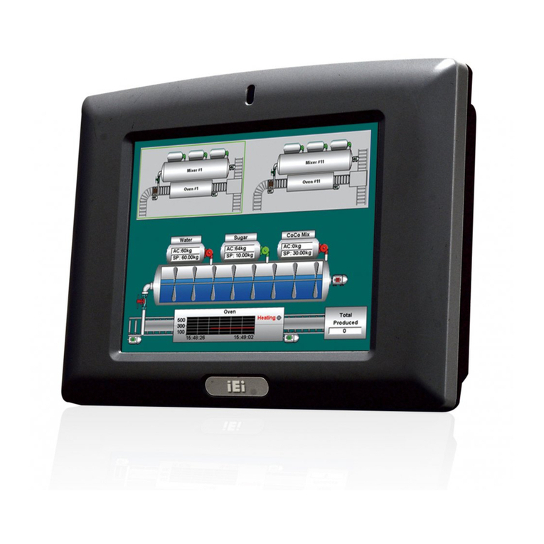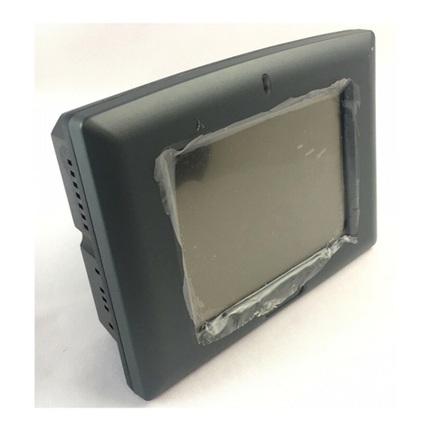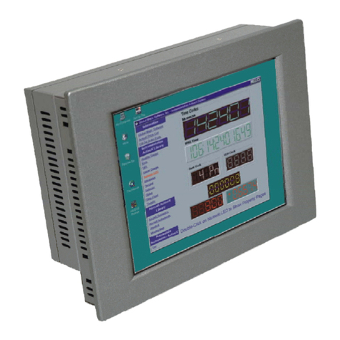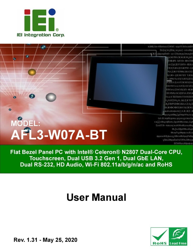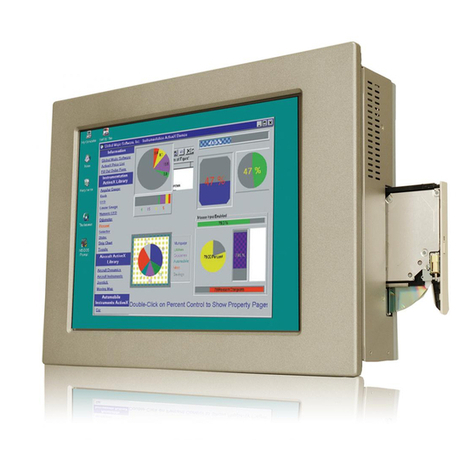
UPC-V312-D525 Panel PC
Page x
Figure 3-27: RJ-45 RS-232 Serial Device Connection...............................................................36
Figure 3-28: RS-422/485 Serial Port............................................................................................37
Figure 3-29: RS-422/485 Cable....................................................................................................37
Figure 3-30: RS-422/485 Serial Port (DB-9)................................................................................38
Figure 3-31: USB Device Connection.........................................................................................39
Figure 3-32: VGA Connector .......................................................................................................40
Figure 3-33: VGA Connector .......................................................................................................41
Figure 3-34: Power Connectors ..................................................................................................42
Figure 3-35: ACC On: AT Mode...................................................................................................43
Figure 3-36: ACC On: ATX Mode.................................................................................................43
Figure 3-37: ACC On: Switch Between PWR1 and PWR2 ........................................................44
Figure 3-38: ACC On: Shutdown.................................................................................................45
Figure 3-39: ACC Off: AT Mode...................................................................................................46
Figure 3-40: ACC Off: ATX Mode ................................................................................................46
Figure 3-41: ACC Off: Switch Between PWR1 and PWR2........................................................46
Figure 3-42: ACC Off: Shutdown.................................................................................................47
Figure 3-43: Remote Control .......................................................................................................48
Figure 5-1: Chipset Driver Screen...............................................................................................80
Figure 5-2: Chipset Driver Welcome Screen..............................................................................81
Figure 5-3: Chipset Driver License Agreement.........................................................................81
Figure 5-4: Chipset Driver Read Me File ....................................................................................82
Figure 5-5: Chipset Driver Setup Operations ............................................................................82
Figure 5-6: Chipset Driver Installation Finish Screen...............................................................83
Figure 5-7: Graphics Driver Read Me File..................................................................................84
Figure 5-8: Graphics Driver Setup Files Extracted ...................................................................84
Figure 5-9: Graphics Driver Welcome Screen...........................................................................85
Figure 5-10: Graphics Driver License Agreement.....................................................................85
Figure 5-11: Graphics Driver Read Me File................................................................................86
Figure 5-12: Graphics Driver Setup Operations........................................................................86
Figure 5-13: Graphics Driver Installation Finish Screen ..........................................................87
Figure 5-14: LAN Driver Welcome Screen .................................................................................88
Figure 5-15: LAN Driver Welcome Screen .................................................................................88
Figure 5-16: LAN Driver Installation ...........................................................................................89
Figure 5-17: LAN Driver Installation Complete..........................................................................89
Figure 5-18: Audio Driver Welcome Screen...............................................................................90
Click to buy NOW!
P
D
F
-
X
C
h
a
n
g
e
V
i
e
w
e
r
w
w
w
.
d
o
c
u
-
t
r
a
c
k
.
c
o
m
Click to buy NOW!
P
D
F
-
X
C
h
a
n
g
e
V
i
e
w
e
r
w
w
w
.
d
o
c
u
-
t
r
a
c
k
.
c
o
m
