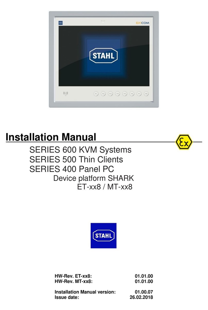
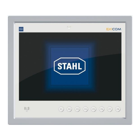
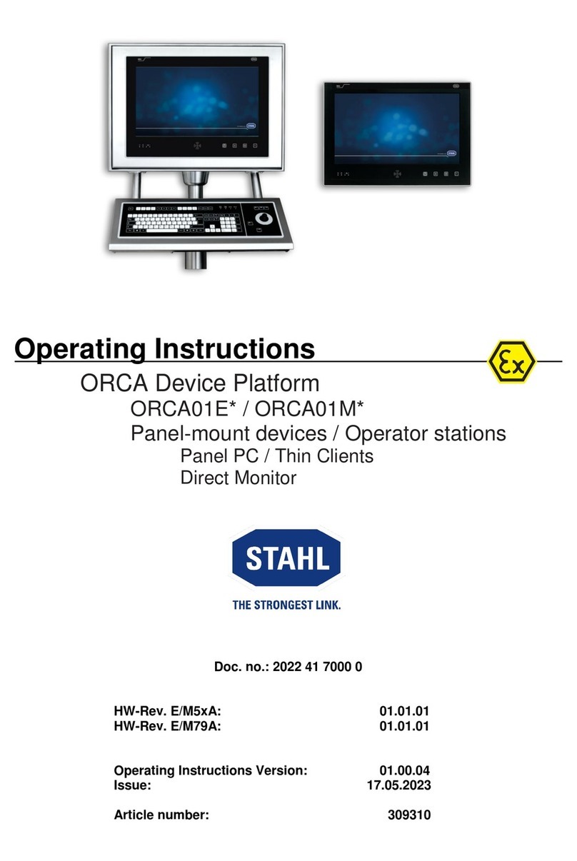
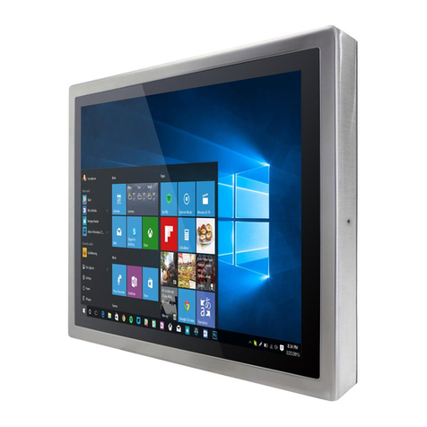
Stahl ET 6-A Series User manual

Installation Manual
SERIES 300 Operator Interfaces
SERIES 400 Panel PC
SERIES 500 Thin Clients
Device platform EAGLE
ET-xx6 / MT-xx6
HW-Rev. ET-xx6-A-FX: 03.00.12
HW-Rev. ET-xx6-A-TX: 03.00.22
HW-Rev. ET-xx6-A-FX-BT: 03.00.16
HW-Rev. ET-xx6-A-TX-BT: 03.00.26
HW-Rev. ET-3x6-A-FX-BS: 03.00.17
HW-Rev. ET-3x6-A-TX-BS: 03.00.27
Installation Manual version: 01.00.02
Issue date: 23.07.2018

Installation Manual ET-/MT-xx6 Publisher
Page 2 of 23 R. STAHL HMI Systems GmbH / IM_ET_MT-xx6_en_V_01_00_02.docx / 23.07.2018
Publisher
Publisher and copyright holder:
R. STAHL HMI Systems GmbH
Adolf-Grimme-Allee 8
D 50829 Cologne
Registered place of business: Cologne
Court of registration: District court Cologne, HRB 30512
VAT number: DE 812 454 820
Phone: (switchboard) +49 (0) 221 76 806 - 1000
(hotline) - 5000
Fax: - 4100
(hotline) support@stahl-hmi.de
All rights reserved.
This document may not be reproduced in whole or in part except with the written consent
of the publisher.
This document may be subject to change (dates, dimensions, weight, constructions,
drawings, images).
Any warranty claims are limited to the right to demand amendments. Liability for any damage that
might result from the contents of these instructions or all other documentation is limited to clear
cases of premeditation.
We reserve the right to change our products and their specifications at any time, provided it is in
the interest of technical progress. The information in the current manual (online or on CD / DVD /
USB stick) or in the operating instructions included in the delivery applies.
Trademark
The terms and names used in this document are registered trademarks and / or products of the
companies in question.
Copyright © 2018 by R. STAHL HMI Systems GmbH. Subject to alterations.

Installation Manual ET-/MT-xx6 Table of contents
R. STAHL HMI Systems GmbH / IM_ET_MT-xx6_en_V_01_00_02.docx / 23.07.2018 Page 3 of 23
Table of contents
Description Page
Publisher 2
Table of contents 3
1Intended use and location 4
2Warning 4
2.1 Touch operation 4
3Enclosure types 5
4Versions mounted on stand or elbow 6
5Mounting 7
5.1 Mounting options 7
5.2 Recommended mounting type 8
5.3 Assembly notes 9
6Tools 9
7Mechanical Installation 9
7.1 Dimensions 10
7.2 Stand mounting 12
7.2.1 View 12
7.2.2 MPFL Stand 12
7.2.3 Mounting –Step by step 13
8Electrical Installation 19
8.1 Connection of the X1 power supply 19
8.2 Stand or enclosure equipotential bonding / earthing 19
8.3 Ethernet interface TX / FX 20
8.3.1 Ethernet interface copper connection TX (X11) 20
8.3.2 Ethernet optical fiber interface FX (X10) 21
9Release notes 22

Installation Manual ET-/MT-xx6 Intended use and location
Page 4 of 23 R. STAHL HMI Systems GmbH / IM_ET_MT-xx6_en_V_01_00_02.docx / 23.07.2018
1 Intended use and location
The ET-/MT-xx6-A-* HMI devices with the EAGLE device platform are equipment for installation
in hazardous areas and can be operated in zones 1, 2, 21 and 22 according to ATEX Directive.
All HMI devices have a modular structure, which makes changes and maintenance easy. They
can be integrated into control cabinets or panels, etc.
2 Warning
2.1 Touch operation
Incorrect / phantom operation:
Incorrect operation of the touch screen may result in accidental functions and errors. The device
will then be unable to execute functions, may execute them incorrectly or in a way not intended.
- Do not realise safety-relevant functions via the touch screen
- Avoid accidental multi-touches
- Do not touch the touch screen across a large area
- Use a touch pen only for the capacitive touch screen
- Before operating the device, thoroughly acquaint yourself with the multi-touch functions of
the operating system and the application
- Switch off the device for cleaning and maintenance
Conductive liquids on thetouch screen can result in incorrect or phantom operations.This applies
in particular to salt water.
- Avoid contamination of the touch screen surface with salt water
Protect the device against rain, snow and splashes, since excessive amounts of standing or
running water will disrupt operation and may cause erratic cursor movement.
This protection can be achieved by using a canopy or some other protective roof-type
construction. Offshore, strong winds, saltwater and rain will have to also be taken into
consideration.
Touch screen damage:
Only touch the touch screen with your finger or a suitable pen.
- Do not touch the screen with pointed or sharp instruments as this may damage the touch
screen, substantially reduce its service life or result in total black-out
Foil membrane blistering / air-pockets:
Extreme ambient conditions (high humidity, temperature) may, in rare cases, result in blistering
or air-pockets underneath the foil touch screen. This does not impede functionality and is a purely
optical phenomenon.

Installation Manual ET-/MT-xx6 Enclosure types
R. STAHL HMI Systems GmbH / IM_ET_MT-xx6_en_V_01_00_02.docx / 23.07.2018 Page 5 of 23
3 Enclosure types
HSG-xx6-VxA-FR HSG-xx6-VxA-CFR
with front door as standard with front door for cleanroom
HSG-xx6-VxA-BD HSG-xx6-VxA-FRS
with rear door (Backdoor) wall mounting
for 10.4" and 15" panel-mount devices only

Installation Manual ET-/MT-xx6 Versions mounted on stand or elbow
Page 6 of 23 R. STAHL HMI Systems GmbH / IM_ET_MT-xx6_en_V_01_00_02.docx / 23.07.2018
4 Versions mounted on stand or elbow
mounted upright on elbow
mounted hanging from elbow
MPFL stand

Installation Manual ET-/MT-xx6 Mounting
R. STAHL HMI Systems GmbH / IM_ET_MT-xx6_en_V_01_00_02.docx / 23.07.2018 Page 7 of 23
5 Mounting
In regards of different applications and ambient conditions we recommend following installation
types:
5.1 Mounting options
Mounted on stand
Ceiling mounting
Elbow upright mounting
Mounted hanging from elbow
Wall mounting (for 10.4" and 15" panel-mount devices only)

Installation Manual ET-/MT-xx6 Mounting
Page 8 of 23 R. STAHL HMI Systems GmbH / IM_ET_MT-xx6_en_V_01_00_02.docx / 23.07.2018
5.2 Recommended mounting type
The following recommended mounting types are the result of trying out many different types over
the years. Please follow these recommendations to ensure the optimum mounting type for your
device.
Before deciding on how to mount the device you need to check the vibration and shock conditions.
We cannot accept any responsibility if you select an unsuitable mounting type that results in
damage or failure of the device.
Conditions present at the
point of installation
Mounting / installation type
Recommendation
No vibration and no
shocks
Mounting on stand, with /
without external
keyboard
No restriction
Ceiling mount with
MPFL stand with /
without external
keyboard
No restriction
Mounted on elbow
standing with / without
external keyboard
No restriction
Mounted on elbow
hanging with / without
external keyboard
No restriction
Wall mounting
with / without external
keyboard
No restriction
Vibration sinusoidal
acc. to IEC 60068-2-6 and
DNV Certification No. 2.4:
5 … 13.2 Hz: ±1 mm
13.2 … 100 Hz: ±0.7 g
X, Y, Z axes
acc. to IEC 60068-2-6:
10 Hz, 1 g
450 Hz, 1 g
Change cycle 1 oct/min
Operating mode 1.2
X, Y, Z axes
Mounting on stand, with /
without external
keyboard
Not recommended
Ceiling mounting with
MPFL stand, with /
without external
keyboard
Not recommended
Mounted on elbow
standing with / without
external keyboard
Not recommended
Mounted on elbow
hanging, with / without
external keyboard
Not recommended
Wall mounting
with / without external
keyboard
No restriction

Installation Manual ET-/MT-xx6 Tools
R. STAHL HMI Systems GmbH / IM_ET_MT-xx6_en_V_01_00_02.docx / 23.07.2018 Page 9 of 23
5.3 Assembly notes
The tightening torques for the cable glands depend on the cables and wires used. This
means the user has to determine the required torques.
The stand / wall bracket must be mounted with at least 4 fastening points. The type of wall
fixing used must be suitable for the wall material.
6 Tools
1x side cutter
1x wire stripping knife
1x wire stripper
1x spanner AF 10
1x spanner AF 13
1x spanner AF 14
1x spanner AF 24
1x spanner AF 30
1x Phillips screwdriver size 1
1x Phillips screwdriver size 2
1x flat-bladed screwdriver 2.5 mm
1x Allen key 5 mm
Mounting the stand or wall-mounting will require other tools not
specified here.
7 Mechanical Installation
Always have two people mount the devices.
CAUTION
NOTE

Installation Manual ET-/MT-xx6 Mechanical Installation
Page 10 of 23 R. STAHL HMI Systems GmbH / IM_ET_MT-xx6_en_V_01_00_02.docx / 23.07.2018
7.1 Dimensions
Dimensions in mm. HSG-xx6-VxA-FR
Device
A
B
C
D
E
F
G
H
I
ET-/MT-x06
ET-/MT-x16
ET-/MT-x36
625
516
190
720
304
400
78
34°
270
ET-/MT-x56
740
568
190
720
304
400
78
34°
270
HSG-xx6-VxA-CFR
Device
A
B
C
D
E
F
G
H
I
ET-/MT-x06
ET-/MT-x16
ET-/MT-x36
625
542
190
720
304
406
78
34°
270
ET-/MT-x56
720
627
190
720
304
406
78
34°
270

Installation Manual ET-/MT-xx6 Mechanical Installation
R. STAHL HMI Systems GmbH / IM_ET_MT-xx6_en_V_01_00_02.docx / 23.07.2018 Page 11 of 23
HSG-xx6-VxA-BD
Device
A
B
C
D
E
F
G
H
I
ET-/MT-x06
ET-/MT-x16
ET-/MT-x36
625
542
195
720
304
442
78
34°
270
ET-/MT-x56
740
568
195
720
304
442
78
34°
270
HSG-xx6-VxA-FRS
X
Mounting tongue for wall mounting
*a
Alternative mounting position of the mounting tongues
Choose suitable mounting screws, rawlplugs and bolts depending on
the actual local requirements and possibilities.
Enclosure dimensions
A
B
C
560
435
190
Mounting tongue dimensions
A
B
C
D
E
F
30
55
35
10.5
10.5
18
NOTE

Installation Manual ET-/MT-xx6 Mechanical Installation
Page 12 of 23 R. STAHL HMI Systems GmbH / IM_ET_MT-xx6_en_V_01_00_02.docx / 23.07.2018
7.2 Stand mounting
7.2.1 View
7.2.2 MPFL Stand
Dimensions in mm.
Stand
A
B
C
D
E
F
G
H
1216
265
200
135
20
101
Ø 60.3
Ø 88.9
Cable glands
Gl1
Gl2
Gl3
M25 x 1.5
M25 x 1.5
M20 x 1.5

Installation Manual ET-/MT-xx6 Mechanical Installation
R. STAHL HMI Systems GmbH / IM_ET_MT-xx6_en_V_01_00_02.docx / 23.07.2018 Page 13 of 23
7.2.3 Mounting –Step by step
Choose suitable mounting screws, rawlplugs and bolts depending on
the actual local requirements and possibilities.
Earthing of stand
8x Ø16
See dimensions "stand"
2
1
NOTE
(See 8.1 Connection of power supply)

Installation Manual ET-/MT-xx6 Mechanical Installation
Page 14 of 23 R. STAHL HMI Systems GmbH / IM_ET_MT-xx6_en_V_01_00_02.docx / 23.07.2018
A mounting holes, for hanging mount
B mounting holes, for upright mount
3 enclosure operating device
D mounting holes in the enclosure of the operating device
Coupling (pre-mounted)
3

Installation Manual ET-/MT-xx6 Mechanical Installation
R. STAHL HMI Systems GmbH / IM_ET_MT-xx6_en_V_01_00_02.docx / 23.07.2018 Page 15 of 23
C M6 Allen screw
E mounting coupling
F stand / wall bracket
or
4
5

Installation Manual ET-/MT-xx6 Mechanical Installation
Page 16 of 23 R. STAHL HMI Systems GmbH / IM_ET_MT-xx6_en_V_01_00_02.docx / 23.07.2018
6
7
tighten all 4 screws with a torque of 10 Nm

Installation Manual ET-/MT-xx6 Mechanical Installation
R. STAHL HMI Systems GmbH / IM_ET_MT-xx6_en_V_01_00_02.docx / 23.07.2018 Page 17 of 23
*1
Connection bolt for equipotential bonding. Already wired to the multiple connection (*2)
in operator stations (OS).
8

Installation Manual ET-/MT-xx6 Mechanical Installation
Page 18 of 23 R. STAHL HMI Systems GmbH / IM_ET_MT-xx6_en_V_01_00_02.docx / 23.07.2018
FRS enclosure
*1
Connection bolt for equipotential bonding. Already wired in operator stations (OS).
*2
Connection for equipotential bonding. See 8.1 Connection power supply
8a

Installation Manual ET-/MT-xx6 Electrical Installation
R. STAHL HMI Systems GmbH / IM_ET_MT-xx6_en_V_01_00_02.docx / 23.07.2018 Page 19 of 23
8 Electrical Installation
8.1 Connection of the X1 power supply
Pin
Signal name
Description
1
+24 VDC
Power supply +24 VDC
2
3
Earth
Power supply 0 VDC
4
8.2 Stand or enclosure equipotential bonding / earthing
see 7.2.3 step 2
1
=
Stand mounting plate
2
=
Washer 2x
3
=
Toothed washer
4
=
Hexagon screw M6x16
5
=
Split washer
6
=
Cable lug with eyelet
9
10

Installation Manual ET-/MT-xx6 Electrical Installation
Page 20 of 23 R. STAHL HMI Systems GmbH / IM_ET_MT-xx6_en_V_01_00_02.docx / 23.07.2018
8.3 Ethernet interface TX / FX
8.3.1 Ethernet interface copper connection TX (X11)
Yellow
Orange
White
Blue
Pin
Signal
Colour
Note
Connection
1
Tx+
Yellow
twist
100Base-TX interface
2
Tx-
Orange
3
Rx+
White
4
Rx-
Blue
11
twist
shielding
clamping
bracket
e.g. cable:
VB-TP-CAT5-Exe-RJ45-Patch
correct
wrong
This manual suits for next models
10
Table of contents
Other Stahl Touch Panel manuals
