Stairmaster FREERUNNER 5600 User manual

F
REE
R
UNNER
5600
OWNER’SMANUAL
®

Page iii
© 2001 StairMaster Health & Fitness Products, Inc., StairMaster, and FreeRunner
are registered trademarks or trademarks of StairMaster Health & Fitness Products, Inc. in the
UnitedStates and/or other countries. StairMaster is a Rutledge Capital company.
P/N 22870-A
Printed in the United States.
© 2001 StairMaster®Health & Fitness Products, Inc.
All rights reserved.
Corporate Headquarters
12421 Willows Road N.E., Suite 100
Kirkland, WA 98034
(800) 635-2936
(425) 823-1825
Fax (425) 823-9490
www.stairmaster.com

Page iv
ThisistocertifythattheStairMaster®FreeRunner™5600ESSelliptical
systemiswarrantedbyStairMasterHealth&FitnessProducts,Inc.tobefreeofall
defectsinmaterialsandworkmanship. Thiswarrantydoesnot apply to any defect caused
bynegligence,misuse,accident,alteration,impropermaintenance,or an “actofGod.”
Thiswarranty isnontransferablefromthe original owner.
If,withinthreeyearsfrom the date of purchase, any part oftheStairMaster
FreeRunnerellipticalsystemshouldfail tooperateproperly (exceptanyaccessories),
contactourCustomerServiceDepartmenttoreporttheproblem. Whencalling,
pleasebe prepared to provide the customerservicerepresentativewiththefollowing
information:
• Yourname, shipping address,andtelephone number.
• Themodel and serial number ofthe inoperable machine.
• Thedate(s)ofpurchaseforthe inoperable machine(s).
• Your billing address.
Thisinformationwillensure that you are the onlyoneorderingparts under your
warrantyagreement.Ifwarrantyreplacementpartsareshippedtoyou,youmaybe
requiredto return the inoperable part. To facilitate this process,thefollowingpolicyhas
beenestablished:
• PleasecallourCustomerService Department to receive a Return Materials
Authorization(RMA)number prior to shipment.
• StairMasterHealth & Fitness Products, Inc. will incurallfreightchargesfor
warranty parts for a machine that is less than45 days old.Youwill not be
responsiblefor the return shipmentof the inoperable parts.
• Someinoperablewarrantyparts must be promptly returned toour
CustomerServiceDepartment. Wewill pay theshippingcost for such
inoperablewarranty parts. Detailed instructions are included with each
warrantyreplacement part.
StairMasterHealth &FitnessProducts,Inc. neithermakes,assumes,nor
authorizesanyrepresentativeor other person to make orassumefor us any other
warrantywhatsoever, whetherexpressedorimplied, inconnectionwiththe sale,service,
orshipmentofourproducts. Wereserve the right to make changes andimprovementsin
ourproductswithoutincurringanyobligationtosimilarlyalterproductspreviously
purchased. Inorderto maintain your productwarrantyand to ensure thesafeand
efficientoperationofyourmachine,onlyauthorizedreplacementpartscanbeused.This
warrantyisvoidifpartsotherthanthoseprovidedbyStairMasterHealth&Fitness
Products,Inc. areused.
Note:Aerosolproductscannot be transported viaair.
WARRANTY

Page v
Regular use of the StairMaster® FreeRunner® 5600 ESS is a safe and effective
way to develop aerobic fitness while conditioning the major muscles of the lower
body. In order to get the best results, and to keep your machine in peak operating
condition, you should carefully read and follow the guidelines presented in this
manual.
WHAT IS IN THIS MANUAL?
The first part of this manual includes sections on safety, installation, operating
instructions, and preventive maintenance. The second part contains detailed
information on problem troubleshooting and repair procedures. An Appendix at
the end of the manual provides important phone numbers, additional instruc-
tionalillustrations, and wiringdiagrams.
Throughout this manual, the console keypad keystrokes are enclosed in
[ ]. The names of the keys and special console operational modes are shown in
capital letters. For example, your machine is ready to use when the console
displays "SELECT WORKOUT". Press the [MANUAL] key to select the MANUAL
workout option.
WHAT IS THE STAIRMASTER FREERUNNER ELLIPTICAL STRIDING
SYSTEM?
The StairMaster FreeRunner 5600 ESS is an elliptical striding system
that allows users to simulate the natural movement path of running without joint
impact or trauma. With its patent pending VSL (Variable Stride Length) technol-
ogy, the FreeRunner permits users to adjust their stride lengths from 10”to 40.”
The FreeRunner also has retractable handles to provide users with the options of
lower body only or total body workouts. Another feature of the FreeRunner is
Polar® heart rate monitoring.
PREFACE

Page vi
SAFETY GUIDELINES ................................................................................... 1
INTRODUCTION ............................................................................................ 3
INSTALLATION INSTRUCTIONS................................................................. 5
BASIC OPERATING PROCEDURES........................................................... 10
General Guidelines for Safe Operation.................................................. 10
Your First Workout.................................................................................. 11
HEART RATE MONITORING ...................................................................... 14
Locked/Non-Locked Option.................................................................... 14
Error Messages ...................................................................................... 15
TELEMETRY (POLAR®) HEART RATE...................................................... 17
Using the transmitter Belt...................................................................... 17
Maintaining the Transmitter Belt........................................................... 18
FREERUNNER 5600 ESS CONSOLE .......................................................... 19
The Display Window .............................................................................. 19
The Numeric Keypad .............................................................................. 20
The Entertainment Keypad..................................................................... 20
The Intensity Level Keys......................................................................... 20
The Stop Key .......................................................................................... 20
The Workout Statistics........................................................................... 21
The Exercise Program Keypad................................................................ 22
The Quick Start Program................................................................. 22
The Manual Program ...................................................................... 22
The Fat Burner Program .................................................................. 23
The Aerobic Training Program......................................................... 23
The Speed Intervals Program.......................................................... 23
The Constant Heart Rate Program.................................................. 24
The Fitness Test Program ....................................................................... 25
Understanding Submaximal Exercise Testing................................. 25
Pretest Screening............................................................................ 27
The StairMaster Submaximal Fit Test.................................................... 27
Console Codes........................................................................................ 31
Custom Codes ................................................................................. 31
CONTENTS

Page vii
Quick Scan Programming ................................................. 32
Machine Status Codes.................................................................... 33
Quick Scan Programming ................................................. 34
Configuration Codes ....................................................................... 34
MAINTENANCE INSTRUCTIONS ............................................................. 35
Helpful Hints........................................................................................... 35
Tool List .................................................................................................. 35
Maintenance Records ............................................................................ 35
InitialService.......................................................................................... 36
Preventive Maintenance ........................................................................ 36
Cleaning ..........................................................................................36
Inspecting........................................................................................36
Lubrication ......................................................................................37
TROUBLESHOOTING .................................................................................. 39
GeneralTroubleshootingGuidelines...................................................... 39
Basic Electrical Theory ........................................................................... 39
The Power Control Board ....................................................................... 39
Systematic Electrical Troubleshooting................................................... 43
Console Diagnostic Tests ....................................................................... 46
Systematic Mechanical Troubleshooting............................................... 51
PARTS REMOVAL AND REPLACEMENT ................................................. 53
Alternator ............................................................................................... 53
Bearings ................................................................................................. 54
Bearing Blocks –Heel Link .............................................................54
Bearing Blocks –Leg Assembly...................................................... 54
Flange Bearings –Heel Link ........................................................... 55
Flange Bearings –Leg Assembly.................................................... 55
Belts .......................................................................................................55
Upper Poly-V Belt............................................................................55
Lower Poly-V Belt............................................................................ 56
Brake System .........................................................................................57
Brake Actuator Arm ........................................................................57
Brake Motor ....................................................................................57
Brake ...............................................................................................58
Cables.....................................................................................................59
CONTENTS

Page viii
Alternator Cable..............................................................................59
Upper Main Cable........................................................................... 59
Lower Brake Cable..........................................................................60
Lower Main Cable...........................................................................60
LimitSwitch Cable ..........................................................................60
Power Connector Cable .................................................................. 62
Stride Sensor Cable ........................................................................63
Chains.....................................................................................................63
Upper Heel Link Chains................................................................... 63
Lower Heel Link Chains...................................................................64
Front Drive Chain Assembly............................................................65
Rear Drive Chain Assembly.............................................................65
Step Chains..................................................................................... 66
Console...................................................................................................67
Console Handlebar .................................................................................67
Covers.....................................................................................................68
Base Cover ...................................................................................... 68
Heel Link Pivot Cover ...................................................................... 68
Safety Panel....................................................................................68
Side Cover.......................................................................................68
Drive Shaft Assembly.............................................................................69
HandleAssembly....................................................................................69
HandleKnob Assembly ..........................................................................70
HeelLink.................................................................................................70
Heel Link Pivot Assembly................................................................ 71
LegAssembly .........................................................................................71
Load Resistor..........................................................................................72
Mounting Blocks ....................................................................................72
Pedal Assembly ......................................................................................73
Pedal Return Springs..............................................................................74
Power Control Board ..............................................................................74
Pulleys ....................................................................................................75
IdlerPulleyAssembly......................................................................75
Intermediate Poly-V Pulley Assembly .............................................75
Lower Poly-V Pulley ........................................................................ 76
Rear Support Bar....................................................................................76
Step ........................................................................................................77
Stride Sensor..........................................................................................77
CONTENTS

Page ix
Spring Cartridge ..................................................................................... 77
Sprockets................................................................................................78
Drive Chain Idler Sprockets and Heel Link Idler Sprockets ............ 78
Drive Sprockets...............................................................................78
Upper Heel Link Idler Sprockets .....................................................79
Turnbuckle Assembly Adjustment................................................... 80
GROUNDING INSTRUCTIONS .................................................................. 81
NOTICE OF FCC COMPLIANCE ................................................................. 82
APPENDICES
Important Phone Numbers ..................................................................... 83
Figures 18-37..........................................................................................84
LIST OF TABLES
Table1: Dimensions and Specifications ..................................................4
Table 2: Fitness Rating Norms (VO2max)...................................................22
Table 3: Recommended Preventive Maintenance Schedule.................. 38
LIST OF ILLUSTRATIONS
Figure 1: Major Parts.................................................................................3
Figure 2: Shipping Components ................................................................5
Figure 3: Tywrap Location .........................................................................6
Figure 4: Cable Locations ..........................................................................7
Figure 5: Level Adjusting End Caps...........................................................8
Figure 6: DC Power Connector ..................................................................9
Figure 7: Correct Foot Placement ............................................................12
Figure 8: Transmitter Belt........................................................................16
Figure 9: The FreeRunner 5600 ESS Console..........................................19
Figure 10: StairMaster Fitness Protocol .................................................29
Figure 11: Alternator Mounting...............................................................53
Figure 12: Belt Location...........................................................................56
Figure 13: Brake Location........................................................................58
Figure14: Limit Switch Assembly...........................................................62
Figure 15: Upper Heel Link Chains .......................................................... 64
CONTENTS

Page x
Figure 16: Grounding System ..................................................................81
Figure 17: Final Assembly - Left Side......................................................84
Figure 18: Final Assembly - Right Side ...................................................85
Figure19: Chain Assemblies...................................................................86
Figure 20: Belt Tension............................................................................87
Figure 21: Drive Shaft Assembly.............................................................88
Figure 22: Leg Assembly .........................................................................89
Figure 23: Heel Link Assembly ................................................................90
Figure 24: Pedal Mounting ......................................................................91
Figure 25: Pedal Assembly ...................................................................... 92
Figure 26: Master Links...........................................................................93
Figure 27: Heel Link Pivot Adjustment ....................................................94
Figure 28: Handle Assembly....................................................................95
Figure29: Limit Switch Assembly...........................................................96
Figure 30: Power Control Board "A" ........................................................97
Figure 31: LED Panel................................................................................98
Figure 32: Power Control Board "B" ........................................................99
Figure 33: Alternator Cable ...................................................................101
Figure 34: Power Supply........................................................................102
Figure 35: Load Resistor........................................................................103
CONTENTS
Page 1
WHEN USING ELECTRICAL EQUIPMENT, ALWAYS FOLLOW THESE BASIC PRECAUTIONS:
IMPORTANT SAFETY INSTRUCTIONS
This symbol appearing throughout this manual means
Attention! Be Alert! Your safety is involved.
The following definitions apply to the words “Danger” and “Warning”
found throughout this manual:
DANGER — Used to call attention to IMMEDIATE hazards
which, if not avoided, will result in immediate, serious personal injury or
loss of life.
WARNING — Used to call attention to POTENTIAL hazards that
could result in personal injury or loss of life.
READ ALL INSTRUCTIONS BEFORE USING THE MACHINE.
To reduce the risk of electrical shock,
always unplug the external power supply
from the AC wall outlet before cleaning,
maintaining,or repairing.
To reduce the risk of burns, fire, electric
shock, or injury to persons:
1. Close supervision is necessary whenever the machine is used by or
near children, invalids, or disabled persons.
2. Do not operate or remove the back cover while the machine is
plugged into a power source. Keep your hands away from all moving
parts.
SAFETY GUIDELINES
!
DANGER
!
WARNING
!

Page 2
3. Use this machine only for its intended use as described in this
manual. Do not use parts, attachments, or accessories other than
those provided by StairMaster®Health & Fitness Products, Inc.
4. Connect the power supply cord to a properly grounded AC wall
outlet; refer to the “Grounding Instructions” section. Keep all cords
away from heated surfaces.
5. To disconnect, remove the plug from the outlet.
6. Never drop or insert any object into any opening on the machine.
7. Do not operate where aerosol (spray) products are being used or
where oxygen is being administered.
8. Do not use the machine outdoors.
9. Never operate this equipment if it has a damaged cord or plug, if it is
not working properly, if it has been dropped or damaged, or dropped
in water. Contact our Customer Service Department at
1-800-331-3578 for help.
10. This equipment is intended for commercial use.
The design of this equipment provides a safety level that can only be
maintained when the equipment is regularly examined for damage and wear.
Inoperable components should be replaced immediately and the equipment
should be taken out of service until it is repaired.
Failure to follow all guidelines may compromise the effectiveness of
the exercise experience, expose anyone on or close to the machine to injury,
and reduce the longevity of the machine. Follow all training instructions listed
in the manual and/or on the machine. Physical injury may result from incorrect or
excessivetraining.
SAFETY GUIDELINES
SAVE THESE INSTRUCTIONS
Page 3
INTRODUCTION
Before leaving the manufacturing facility in Tulsa, Oklahoma, your
StairMaster®FreeRunner®Elliptical Striding System was thoroughly
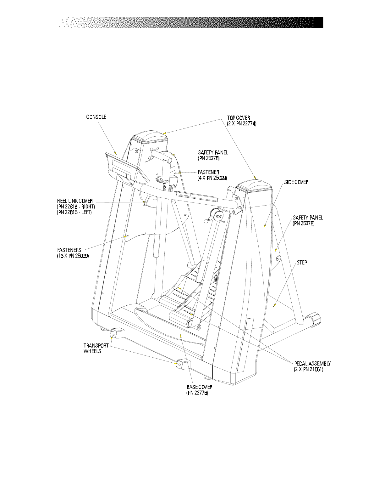
inspected and tested to ensure proper operation. The major parts of the
machine are shown in Figure 1.
Figure 1: Major Parts

Page 4
Throughout this Manual, all references to the left or right side and
to the front or back are made as if you were on the machine, ready to
exercise. For example, the console is located on the front of the machine.
The dimensions and general specifications of the machine are listed in
Table1.
Table 1. Dimensions and Specifications for the StairMaster®
FreeRunner® Elliptical Striding System
INTRODUCTION
Physical Dimensions:
Height 64.0”(163cm)
Depth
at base 40.0”(102cm)
w/Console & Back Platform 48.0”(122cm)
Width 52.0”(132cm)
Weight 485.0 lbs (220 kg)
Range of Motion:
Maximum stride length 54”
Peak elliptical pattern 12 “- 36”
Power Supply Specifications*:
Input Voltage 110-120 VAC, 50/60 Hz
Output Current Capacity 2.5Amps
Input Power Consumption 55 Watts
*Optional power supplies, intended for use outside the United States, are
available for 220-240 VAC, 50/60 Hz power requirements.

Page 5
Your FreeRunner®is shipped complete with all parts required for assembly. Study
the assembly instructions carefully. The shipping components are shown below
in Figure 2. Contact our Customer Service Department at (800) 331-3578 for
assistance. International customers should contact their local distributors.
Figure 2: Shipping Components
INSTALLATION INSTRUCTIONS
STEP
*POWER SUPPLY NOT SHOWN
(PN 24381)
CONSOLE HANDLEBAR
CONSOLE KNOB
(4 X PN 24677)
LOCK WASHER
(4 X PN 22138)
CONSOLE
READINGRACK
(PN 22775)
MOUNTING SCREWS
(18 X PN 25176)
1
(1) (1)
(1)
Page 6
A.Assemble the Machine:
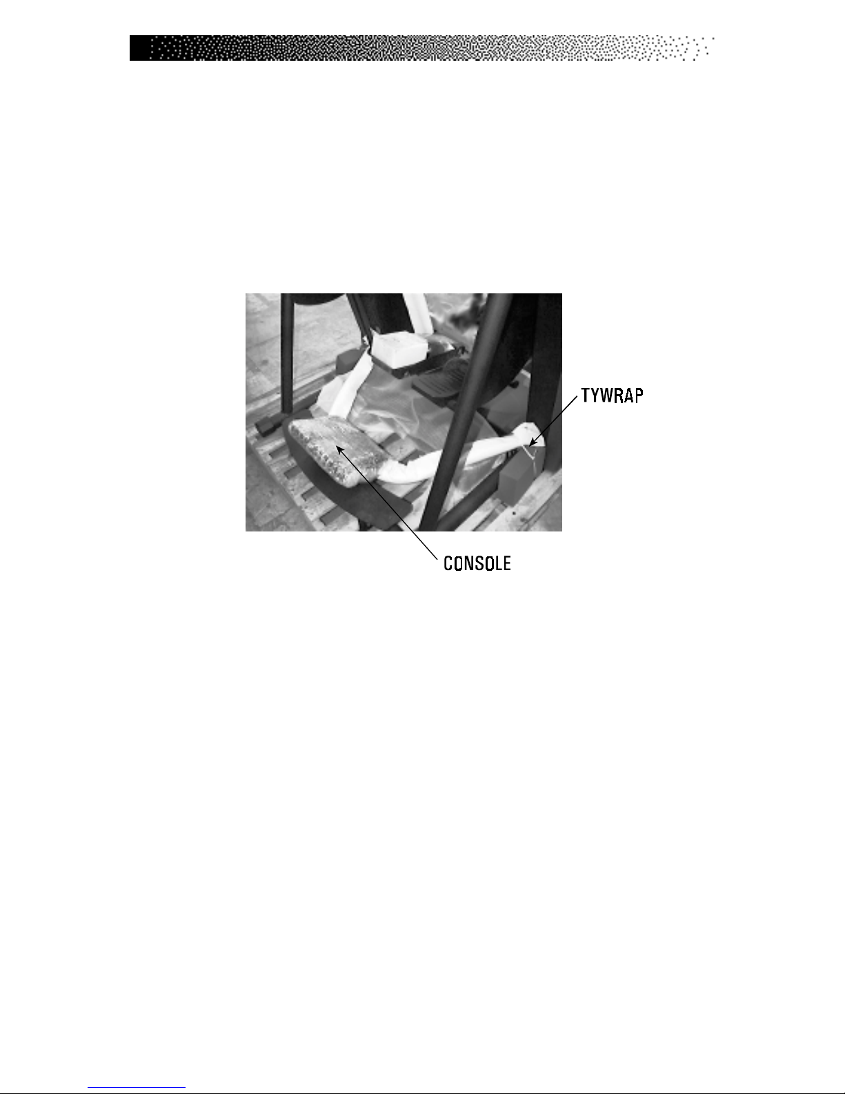
1. Cut each tywrap that secures the console handlebar to the rear
support bars (see Figure 3). Remove the foam protection from each
side of the handlebar. Lift the handlebar out from under the pedals.
Set the handlebar with console aside. Remove the step from under
the pedals and set the step aside.
Figure 3: Tywrap Location
2. Remove the shrink wrap from the pedal, and lift the power supply box,
owner’s manual, and hardware bag off the pedal. Set the parts aside.
3. Remove the top covers. Use the fastener removal tool from the
hardware bag to remove the top cover rivets. Disconnect the Polar®
heart rate receiver under the right top cover from the upper Polar
heart rate cable (see Figure 4).
4. Have an assistant support the console handlebar. Stand on the right
side of the machine and connect the lower Polar heart rate cable from
the handlebar to the upper Polar heart rate cable in the frame.
Connect the upper Polar heart rate cable to the heart rate receiver
and reinstall the top cover.
5. Stand on the left side of the machine and connect the upper main
cable coming out from the handlebar to the lower main cable from the
frame. Next, connect the upper brake cable from the handlebar to the
INSTALLATION INSTRUCTIONS

Page 7
lower brake cable from the frame. Tuck any excess slack in the cables
up inside the handlebar.
6. Attach the console handlebar to the frame. To prevent the rivnuts (see
Figure 4) from spinning in the frame, hold the rivnuts with pliers while
securing the mounting screws to the frame.
Figure 4: Cable Locations
7. Have an assistant help you slide the machine off the shipping pallet
and onto the floor. Use the transport wheels (see Figure 1) to roll the
machine into the desired location.
8. Remove the packing material from the console, handlebar, and step.
Place the step inside the rear supports and insert a mounting screw
and a washer into each step hole. Tighten each screw.
INSTALLATION INSTRUCTIONS

Page 8
B. Level the Machine:
1. Make sure the machine is level before you use it for the first time.
The rubber end caps (see Figure 5) are designed to compensate for
uneven floors. Each face of the caps is a different thickness. Twist
the caps to stabilize the machine.
Figure 5: Level Adjusting End Caps
C. Connect the Power Supply:
1. Remove the external power supply from the shipping box. Connect
the DC power cable to the DC power connector located on the lower
left side (see Figure 6).
2. Place the power supply on the floor near an AC wall outlet. To reduce
the hazard of electrical shock, place the power supply in a location
away from the machine and away from exposure to perspiration. You
should not place your power supply on carpet because it may
overheat.
INSTALLATION INSTRUCTIONS
TO REDUCE THE RISK OF ELECTRICAL SHOCK AND FIRE AND TO
PREVENT SEVERE DAMAGE TO THE MACHINE, USE ONLY THE
POWER SUPPLY APPROVED FOR USE WITH THIS EQUIPMENT.
IN ADDITION, YOUR MACHINE MUST BE PROPERLY GROUNDED.
WARNING
!

Page 9
Figure 6: DC Power Connector
4. Connect the AC power cord to the AC wall outlet. Refer to the
“Grounding Instructions”section if the AC wall outlet does not accept
a three-prong plug.
5. Watch the console. The console should display a software revision code
and then show “SELECT WORKOUT.”If it does not, unplug the power
supply, then plug it back in. If the console still does not power up
correctly, contact our Customer Service Department. Refer to the
Appendix for the appropriate telephone number.
6. The console ready to use when the display “SELECT WORKOUT”is
shown.
DCPOWER CONNECTOR
3. Check to be sure that the input AC power rating marked on the
power supply matches the available power. If it does not, obtain the
matching power supply from StairMaster®Health & Fitness Products,
Inc. before proceeding any further.
INSTALLATION INSTRUCTIONS

Page 10
GENERAL GUIDELINES FOR SAFE OPERATION
1. Obtain a complete physical examination from your medical doctor, and
enlist a health/fitness professional’s aid in developing an exercise
program suitable for your current health and fitness status.
2. When working out for the first time, use the MANUAL exercise
program at a low intensity level until you feel comfortable and
capable of higher resistance levels.
3. The intensity and duration of your exercise program should always be
subject to how you feel. Never permit peer pressure to influence your
personaljudgment while exercising.
4. Overweight or severely deconditioned individuals should be
particularly cautious when using the machine for the first time. Even
though such individuals may not have a history of serious physical
problems, they may perceive the exercise to be far less intense than it
really is, resulting in the possibility of overexertion or injury.
5. Although all equipment manufactured by StairMaster®Health &
Fitness Products, Inc. has been thoroughly inspected by the
manufacturing facility prior to shipment, proper installation and
regular maintenance are required to ensure safety. Maintenance is
the sole responsibility of the owner.
BASIC OPERATING PROCEDURES
THESE GUIDELINES ARE DIRECTED TO YOU, AS THE OWNER OF THE MACHINE.
YOU SHOULD INSIST THAT ALL USERS FOLLOW THE SAME GUIDELINES. YOU
SHOULD MAKE THIS MANUAL AVAILABLE TO ALL USERS.
WARNING
!
Page 11
YOUR FIRST WORKOUT ON THE STAIRMASTER®FREERUNNER®
ELLIPTICAL STRIDING SYSTEM
Basic Instructions for First-Time Users
1. Warm up with light calisthenics and easy stretching exercises for at
least five minutes before beginning your exercise program.
BASIC OPERATING PROCEDURES
2. Stand on the step, and then step forward onto the pedals (see
Figure 7). Notice that the pedals are braked in position. Pressing a
workout key will disengage the brake. The brake can also be disen-
gaged by pushing the pedals apart forcibly. However, this is not
reccomended as it will cause premature wear on the brake assembly.
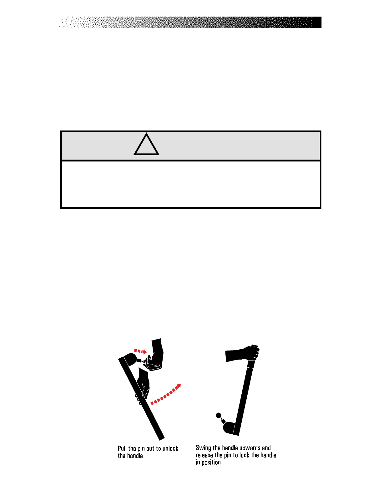
3. To raise or lower the retractable handles, pull the handle adjustment
knob out on each handle to move the handle (see Figure below). Ensure
that each knob is locked into place before beginning your workout.
Note: Always hold onto the handles when they are in the upright position.
IF AT ANY TIME DURING YOUR WORKOUT YOU FEEL CHEST PAIN,
EXPERIENCE SEVERE MUSCULAR DISCOMFORT, FEEL FAINT, OR SHORTNESS
OF BREATH, STOP EXERCISING IMMEDIATELY. IF THE CONDITION PERSISTS,
YOU SHOULD CONSULT YOUR MEDICAL DOCTOR IMMEDIATELY.
WARNING
!
Table of contents
Other Stairmaster Elliptical Trainer manuals

Stairmaster
Stairmaster ClubStride 5100-LE User manual

Stairmaster
Stairmaster FreeRunner 5400 ESS User manual

Stairmaster
Stairmaster FREEC LIMBER Silver 4200 PT Installation and operating instructions

Stairmaster
Stairmaster FreeClimber User manual

Stairmaster
Stairmaster ClubStride 5100 NSL User manual

Stairmaster
Stairmaster SC916 StairClimber User manual


