STALGAST Radom sp. z o.o. ul. Staniewicka 5 03-310 Warszawa
tel.: 22 517 15 75 fax: 22 517 15 77 www.stalgast.com email: stalgast@stalgast.com
device is not allowed. All of the above should only use the appliance under supervision of a
person responsible for their health and safety.
•Pay attention to the children not to play with the appliance. Particularly with hot burners, pan
supports, grids and pots with hot liquids as they can cause scalding of the child.
•During use, work surfaces get hot. Be careful to avoid touching hot parts.
•Do not open the gas supply valve or a valve on the gas cylinder without checking whether all
thermostat knobs are closed.
•Do not place pots directly on the burners.
•Do not hit the knobs and burners.
•Do not slam the oven door or and do not overload the oven.
•Do not turn on the knobs without holding in hand the device to ignite the gas.
•Do not extinguish the burner flame by blowing.
•Always use heat protective gloves while placing and removing pots.
•Do not allow to flood or dirty the burners. Clean and dry the burners immediately after cooling.
•Do not leave the appliance unattended during operation. Hot oils and fats may ignite due to
overheating.
If you suspect a gas leak, NEVER:
•Light matches, smoke cigarettes, turn on and off electric appliances (door bell or light
switch) and use other electrical and mechanical equipment causing t an electric or impact
spark. In such case, immediately close the shut-off valve on the gas supply installation or
on the liquid gas cylinder and ventilate the area and then call the person authorized to
remove the cause.
•In the case of ignition of gas escaping from a leaky installation immediately shut off the gas
supply using the shut-off valve.
•In case of ignition of gas escaping from a leaky liquid gas cylinder valve, cover the cylinder
with a wet blanket to cool it and then turn off the cylinder valve. After cooling move the
cylinder into the open air. Never use this cylinder again.
•When the appliance is not going to be used for several days close the main valve on the gas
installation, whereas when using a liquid gas cylinder- after each use.
•Cooking and baking causes heat and moisture emission in the room in which the appliance is
installed. Make sure that the room is well ventilated, keep natural ventilation holes open or
install a mechanical ventilation (hood with mechanical extract).
•Control appliance functioning during use.
•Always use heat protective gloves while placing and removing pots.
•Do not open the gas supply valve or a valve on the gas cylinder without checking whether all
thermostat knobs are closed.
•Turn off the gas supply on the appliance control panel and shut-off valve after the appliance
operation and during cleaning.
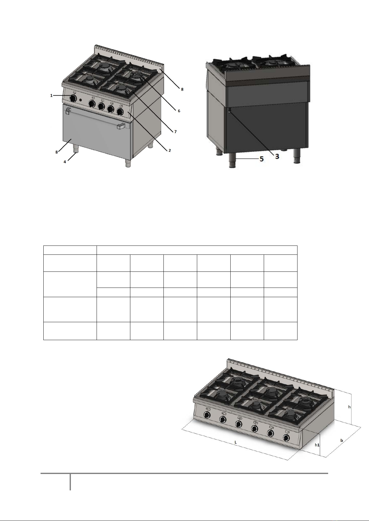
2. TECHNICAL SPECIFICATION
BURNERS CHARACTERISTICS :
This manual applies to the group of gas appliances equipped with high-power burners with flame
stabilization, which meet the requirements of norms PN-EN 203-1+A1:2010 ; PN-EN 203-2-1:2010
and PN-EN 203-2-2:2010- all comply with the Directive 2009/142/EC.
Gas appliances are adapted to use the following gases:
2E -group 2 subgroup E (20mbar) – high methane natural gas (G20)
2Lw - group 2 subgroup L (20mbar) – nitrogen-rich natural gas (G27)
3B/P - group 3 subgroup B/P (37mbar) – propane-butane gas (G30)