STAMPA Quadrifoglio User manual
TW525/01
Slampa
TLF
27/03/2007
3LIK0205
S+e
in
\e:>~
S \-ee.\
e)C.h'"o..c.rof
~
:;,
-CAPPA ASPIRANTE -lstruzioni per l'uso
~
DUNSTABZUGSHAUBE- Gebrauchsanweisung
~
CAMPANA EXTRACTORA -Manual de utilizaci6n
_..
HOTTE DE CUISINE -Notice d'utilisation
~
COOKER HOOD -User instructions '
.~·
AFZUIGKAP -Gebruiksaanwijzing
·~
COIFAASPIRANTE- Manual do usuario
>--0
m--0
o--0
c--0
m--0
,
__
_
~~---------------
'"'"\,
·.
cr
,
rg
. '
. '
·----
___
f .\
\,
&
~·
"""i
~
'<
I
~o~~-u
~~
.-~~
. t '
....
~
......
If~
1....
·······
0
3
"'
X
CD
0
(")
3

Fig.7
-
A
A B C
+ l +
•eoeee
t t t t t t
(o(Q¢
(I)
o[J~)
t t /
ttt
A1
A2
C1
C21C4
C3
I I I I I I
G B c D E A
1
1 1
11
1 1
1
.
•~oo
01
02
03
0©.
B
Fig.S Fig.9
-
4-
TW525
ITALIANO CD
GENERALITA'
Leggere attentamente
il
contenuto del presente libretto
in
quanta fornisce importanti indicazioni riguardanti
Ia
sicurezza di installazione, d'uso e di manutenzione.
Conservare
il
libretto per ogni ulteriore consultazione.
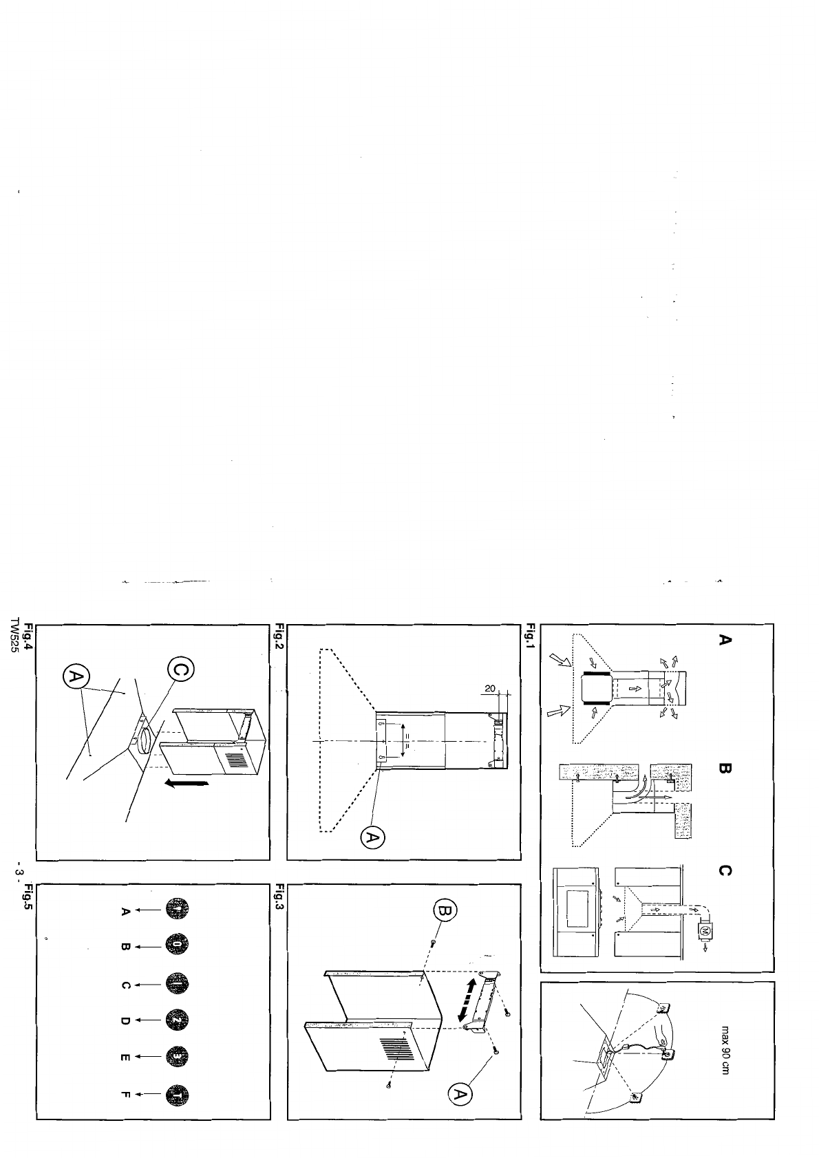
L'apparecchio e stato progettato per usa in versione
aspirante (evacuazione aria all'esterno •
Fig.1
B),
filtrante
(riciclo aria all'interno ·
Fig.1
A)
o con motore esterno
(Fig.1C).
AWERTENZE PER
LA
SICUREZZA
1. Fare attenzione se funzionano contemporaneamente
una cappa aspirante e
un
bruciatore o
un
focolare
dipendenti dall'aria dell'ambiente ed alimentati da
un'energia diversa da quella elettrica,
in
quanta
Ia
cappa
aspirando toglie all'ambiente !'aria di cui
il
bruciatore o il
focolare necessita per
Ia
combustione.
La
pressione
negativa nel locale non deve superare i 4
Pa
(4x1
0-5
bar). Per
un
funzionamento sicuro, provvedere quindi
ad
un'opportuna ventilazione del locale. Per l'evacuazione
esterna attenersi aile disposizioni vigenti
nel
vostro paese.
Prima
di
allacciare il
modello
alia rete elettrica:
·
controllare
Ia
targa
dati
(pasta
all'interno
dell'
apperecchio) per accettarsi che
Ia
tensione e potenza
siano corrispondenti a quella della rete e
Ia
presa di
collegamento sia idonea.
In
caso
di
dubbio interpellare
un
elettricista qualificato.
Se
il
cava
di
alimentazione edanneggiato, esso deve
essere sostituito da
un
cava o
un
assieme speciali di-
sponibile presso
il
costruttore o
il
suo servizio assisten-
za
tecnica.
2.ATTENZIONE!
In determinatecircostanzegli elettrodomestici possono
essere
pericolosi.
A) Non cercare
di
controllare
i
filtri
con
Ia
cappa in
funzione
B)
Nontoccare le lampade e le zone adiacenti, durante
e
subito
dopo
l'uso
prolungato
dell'impianto
di
illuminazione.
C)
E'
vietato
cuocere
cibi
alia fiamma
sotto
Ia cappa
D)
Evitare Ia fiamma Iibera, perche
dannosa
per
i
filtri
e
pericolosa
per
gli
incendi
E)
Controllare
costantemente i
cibi
fritti
per
evitare
che !'oliosurriscaldato prenda
fuoco
F)
Prima
di
effettuare
qualsiasi
manutenzione,
disinserire
Ia
cappa dalla rete elettrica.
Questa apparecchio econtrassegnato
in
conformita alia
Direttiva Europea 2002/96/EC, Waste Electrical and
Electronic Equipment (WEEE). Assicurandosi che questa
prodotto sia smallito
in
modo corretto, l'utentecontribuisce
a prevenire le potenziali conseguenze negative per
l'ambiente e
Ia
salute.
II
simbolo
~
sui prodotto o sulla documentazione di
accompagnamento indica che questa prodotto non deve
essere trattato come rifiuto domestico ma deve essere
consegnato presso l'idoneo punta di raccolta per il
riciclaggio
di
apparecchiature elettriche
ed
elettroniche.
Disfarsene seguendo
le
normative
Jocali
per
Ia
smaltimento
dei rifiuti. Per ulteriori informazioni sui trattamento,
recupero e riciclaggio di questa prodotto, contattare
l'idoneo ufficio locale,
il
servizio di raccolta dei rifiuti
domestici 0
il
negozio presso
il
quale
il
prodotto estato
acquistato.
ISTRUZIONI PER L'INSTALLAZIONE
Le operazioni
di
montaggio
e
collegamento
elettrico
devonoessere effettuateda personate specializzato.
• Collegamento elettrico
L'apparecchio e costruito in classe II, percio nessun
cava deve essere collegato alia presa di terra.
L'allacciamento alia rete elettrica deve essere eseguito
come segue:
MARRONE= L linea
BLU = N neutro
Se
non
prevista, montare sui cava una spina normalizzata
per
il
carico indicato nella etichetta caratteristiche.
Se
provvista di spina, fare
in
modo che sia facilmente
accessibile dopa l'installazione dell'apparecchio.
Nel caso di collegamento diretto alia rete elettrica e
necessaria interporre tra l'apparecchio e
Ia
rete
un
interruttore onnipolare con apertura minima Ira i contatti
3
mm,
dimensionato
a!
carico e rispondente aile norme
vigenti.
•
La
distanza minima Ira
Ia
superticie
di
supporto dei
recipienti
di
cottura sui dispositivo di cottura e
Ia
parte
piu bassa della cappa da cucina deve essere
di
almena
65
em.
Se dovesse1
essere usato
un
tuba di connessione
composto
di
due o piu parti,
Ia
parte superiore deve
essere all'esterno
dL
quella inferiore. Non collegare
Ia
scarico della cappa ad
un
condotto
in
cui circoli aria
calda o utilizzato per evacuare fumi degli apparecchi
alimentati da un'energia diversa
da
quella elettrica. Prima
di procedere aile operazioni
di
montaggio, per una piu
facile manovrabilita dell'apparecchio disinserire i filtro/i
antigrasso (Fig.6).
Nel caso di montaggio dell'apparecchio
in
versione
aspirante predisporre
il
foro di evacuazione aria.
• FISSAGGIO A PARETE
Eseguire i fori A rispettando
le
quote indicate (Fig.2).
Fissare J'apparecchio
al
muro
ed
allinearlo
in
posizione
orizzontale con i pensili. A regolazione avvenuta fissare
Ia
cappa definitivamente tramite le 2 viti A (Fig.4).
Peri vari montaggi utilizzare viti e tasselli
ad
espansione
idonei
al
tipo
di
muro (es. cementa armata, cartongesso,
ecc). Nel caso
in
cui le viti e i tasselli siano forniti
in
dotazione con
il
prodotto accertarsi che siano idonei per
il tipo
di
parete
in
cui deve essere fissata
Ia
cappa.
• Se
il
vostro apparecchio estato progettato per l'utilizzo
in
abitazioni fornite di aspirazione centralizzata eseguire
le seguenti operazioni:
·L'interruttore comanda l'apertura e
Ia
chiusura
di
una
valvola tramite
un
dispositivo termoelettrico. Commutando
l'interruttore nella posizione
ON,
dopa
un
minuto,
Ia
valvola
si
apre ruotando di 90° permettendo cosi l'aspirazione
dell'aria viziata. Commutando l'interruttore nella posizione
OFF, dopa 100 secondi,
Ia
valvola
si
chiude.
•
FISSAGGJO
DEl
RACCORDITELESCOPICJ
DECORATIVI
Predisporre J'alimentazione elettrica entro J'ingombro del
raccordo decorativo.
Se
il
vostro apparecchio deve essere
installato
in
versione aspirante o in versione motore
esterno, predisporre
il
foro evacuazione aria. Regolare
Ia
larghezza della staffa
di
supporto del raccordo superiore
(Fig.3). Successivamente fissarla
al
soffitto
in
modo che
sia
in
asse con
Ia
vostra cappa tramite
le
viti A (Fig.3) e
rispettando
Ia
distanza dal soffitto indicata in Fig.2.
Collegare, mediante
un
tuba
di
raccordo,
Ia
flangia C
a!
foro evacuazione aria (Fig.4).
lnfilare
il
raccordo superiore all'interno del raccordo
inferiore
ed
appoggiare sopra
Ia
scocca.Sfilare
il
raccordo
superiore fino alia staffa efissarlo tramite
le
viti B (Fig.3).
TW525
-5-

d'abord
Ia
largeur
de
Ia
bride
de
support
du raccord
superieur
(Fig.3), ensuite Ia fixer au plafond,
de
maniere
a
ce
qu'elle
soil
sur
l'axe de votre hotte au
moyen
des
vis A (Fig.3),
tout
en respectant Ia distance
depuis
le
plafond indiquee a Ia Fig.2.
Raccorder
Ia bride C au trou
d'evacuation
de l'air au moyen
d'un
tube
de
raccorde-
ment
(Fig.4).
lntroduire le raccord superieur a l'interieur du raccord
inferieur et
appuyer
sur
Ia coque.
. Retirer le raccord superieur
jusqu'a
Ia
bride et le fixer au
moyen
des
vis B (Fig.3). Si
on
veut
transformer
Ia hotte
du modele aspirant au
modele
filtrant,
demander
a votre
revendeur les filtres au charbon actif et suivre les ins-
tructions de montage.·
• MODELE FILTRANT .
Installer Ia hotte
et
les
deux
raccords
suivant
I'
indication
reportee au
paragraphe
concernant
le
montage
de
Ia
hotte
dans
le
modele
aspirant. En cas
de
montage
du
raccord filtrant, se
rapporter
aux
instructions
figurant
dans
le jeu. Si le jeu
n'est
pas
fourni,
commandez-le
a
votre revendeur
comme
accessoire. Les filtres
doivent
etre appliques au
groupe
aspirant
situe a l'interieur
de
Ia
hotte en les
centrant
par
rapport au groupe aspirant
et
en les
tournant
de
90
degres
jusqu'au
declic d'arret.
EMPLOI
ET
ENTRETIEN
•
Nous
vous
recommandons
de
mettre
Ia
hotte en route
avant
de
commencer
a cuisiner.
Les filtres
doivent
etre appliques
sur
le
groupe
d'aspira-
tion situe a l'interieur de Ia hotte en les centrant et en les
faisant
tourner
de
90
degres
jusqu'au
blocage.
Le bon
fonctionnement
de
Ia hotte est lie a
Ia
frequence
des
operations
d'entretien,
et
plus
particulierement
a
l'entretien du filtre anti-graisse et du filtre au charbon
act
if.
• Les
filtres
anti
graisse
ont
pour
role
de
retenir
les
particules grasses en
suspension
dans
l'air. lis
peuvent
done se
boucher
plus ou moins rapidementselon l'usage
de Ia hotte.
Dans
tous
les cas,
pour
prevenir
un
eventuel
risque
d'incendie, il est necessaire
de
nettoyer
au moins tous
les
deux
mois le filtre en suivant les indications
suivan-
tes:
-Retirer les filtres
de
Ia
hotte et les laver
avec
de l'eau
et un
detergent
liquide neutre, laisser Ia salete se decol-
ler.
-Rineer
abondamment
a l'eau
tiede
et
laisser secher.
-Les filtres
peuvent
egalement
etre laves
dans
le lave
vaisselle.
Apres plusieurs lavages
des
panneaux
en aluminium, on
peutconstater
un
changementde leurcouleur. Ceci n'ouvre
pas droit a reclamation afin
d'obtenir
un eventuel chan-
gement
des
panneaux.
• Les filtres au charbon actif servent a filtrer l'air qui
sera
rejete
dans
Ia
piece. Les filtres ne
sont
ni lavables ni
regenerables
et
doivent
etre
changes
tous les trois mois
au maximum. La saturation du
charbon
actif depend
de
!'utilisation plus ou moinsprolongee
de
l'appareil, du type
de cuisine effectue et de Ia regularite
avec
laquelle est
effectue le nettoyage du filtre anti graisse.
• Nettoyer
frequemment
tousles
depots
sur
le ventilateur
et les
autres
surfaces,
en
utilisant
un
chiffon
imbibe
d'alcool
denature
ou de
detergents
liquides neutres non
abrasifs.
• L:eclairage
de
cette
hotte
est
destine
a
etre
utilise
uniquement
lorsque vous cuisinez.
II
n'est
pas
destine
pour
une illumination generale et
pour
une longue duree;
dans
ce cas les
ampoules
peuvent
se brOier. Pourant
veuillez
eteindre
l'eclairage
des
que
vous
avez
!ermine
de cuisiner.
•
COMMANDES:
(Fig.5)
Lumineux
le
symbole
son!
le
suivant:
A=
touche
ECLAIRAGE
B
=touche
OFF
C
=touche
PREMIERE
VITESSE
D
=touche
DEUXIEME
VITESSE
E
=touche
TROISIEME
VITESSE
F
=touche
MINUTEUR
ARRET
AUTOMATIQUE 15 minu-
tes
• Si votre appareil
possede
Ia fonction vitesse
INTENSE,
maintenir
appuye
pendant
environ 2
secondes
le bouton
E
pour
activer
Ia fonction
pendant
10 minutes,
apres
quoi elle retournera a Ia vitesse etablie en precedence.
Quand Ia fonction est active, Ia
LED
clignote.
Pour
l'in-
terrompre
avant
les 10 minutes,
presser
de
nouveau
sur
Ia
touche
E.
• En
appuyant
sur
le bouton F
pendant
2
secondes
(lors-
que
Ia hotte est allumee), Ia fonction "
clean
air
, s'ac-
tive.
Celie
fonction
demarre
le
moteur
pour
10
minutes
par
heure a Ia
premiere
vitesse.
Des que Ia fonction est activee, le
moteur
demarre en 1
'"
vitesse
pour
10
minutes
pendant
lesquelles les boutons
F et C
doivent
clignoter en
meme
temps. A Ia fin
de
ce
temps, le
moteur
s'arrete et
Ia
diode electroluminescente
du bouton F reste allumee
sans
clignoter
jusqu'a
ce que
le
moteur
reparte en
1'''
vitesse
50
minutes
plus
lard.
Les diodes electroluminescentes F
etC
recommencent a
clignoter
pendant
10
minutes
et ainsi
de
suite. En ap-
puyant
sur
n'importe
quelle
touche
a
!'exception
des
touches
de
lumiere, Ia hotte retourne
immediatement
a
son
fonctionnement
normal (ex. en
appuyant
sur
le bou-
ton D
Ia
fonction "
clean
air
,
se
desactive
et
le
moteur
passe
directement
a Ia 2'm' vitesse ; en
appuyant
sur
le
bouton
B Ia fonction se desactive)
•
Saturation
filtres
anti-gras/charbon
actif:
-
Quand
Ia
touche
A
se
met
a
clignoter
par
intervalles
de
2
secondes,
il
est
temps
de
laver les filtres
anti-gras.
-
Quand
Ia
touche
A se
met
a
clignoter
par
intervalles
de
0,5
secondes,
il
esttemps de changerlesfiltres a
charbon.
Apres avoir remis le filtre propre a
sa
place,
proceder
a
une remise a zero
Ia
memoire electronique en appuyant 5
secondes
de
suite
sur
Ia
touche
A
jusqu'a
ce
que
cette
derniere
cesse
de clignoter.
•COMMANDES: (Fig.9A) Mecaniques_(Fig.9B) Ellyptique
les
symboles
sont
les suivants:
A=
touche
ECLAIRAGE
B
=touche
OFF
C
=touche
PREMIERE
VITESSE
D
=touche
DEUXIEME
VITESSE
E
=touche
TROISIEME
VITESSE
G=
voyant MOTEUR EN MARCHE
•
MAN
DOS: (Fig.S)
SLIDER
le
symbole
sont
le suivant:
A =
lnterrupteur
lumiere
A1 = bouton
Off
A2
=bouton
On
B
=bouton
voyant
GEMMA
C = Contr61e
de
vitesse
C1
= bouton
Off
C2
=bouton
PREMIERE
VITESSE
C3
=bouton
SECONDE
VITESSE
C4
=bouton
TROISIEME
VITESSE
NOUS DECLINO.STOUTE
RESPON~ABILITE
POUR LES
EVENTUELS
DEGATS PROVOQUES PAR
L'INOBSER-
VATION DES SUSDITESINSTRUCTIONS.
-
12-
T\1\/<;?o;
ENGLISH @
GENERAL
Carefully read thefollowing important information regard-
ing installation
safety
and maintenance. Keep this infor-
mation booklet accessible
for
further consultations.
The
appliance has been
designed
for use in the dueling
version (air
exhaust
to the
outside
-Fig.1 B), filtering
version (air circulation on the inside -Fig.1 A)
or
with
external
motor
(Fig.1 C).
SAFETY PRECAUTION
1. Take care
when
the
cooker
hood is operating simulta-
neously
with an open fireplace
or
burner
that
depend
on
the
air
in the
environment
and are supplied
by
other
than
electrical energy,
as
the
cooker
hood removes the
air
from the environmentwhich a burner
or
fireplace need for
combustion.
The
negative pressure in the
environment
must
not
exceed
4Pa
(4x10⁻⁵ bar). Provide
adequate
ventilation in the
environment
for a safe operation
of
the
cooker
hood.
Follow the local laws applicable
for
external air
evacua-
tion.
Before
connecting
the
model
to
the
electricity
net-
work:
-control
the
data
plate (positioned inside
the
appliance)
to ascertain
that
the voltage and
power
correspond to
the
network
and the
socket
is suitable. If
in
doubt
ask
a
qualified electrician.
If the
power
supply cable is damaged, it
must
be replaced
with
another
cable
or
a special assembly, which may be
obtained directfrom the manufacturer
or
from theTechnical
Assistance Centre.
2.WARNING!
In
certain
circumstances
electrical
appliances
may
be
a
danger
hazard.
A)
Do
not
check
the
status
of
the
filters
while
the
cooker
hood
is
operating
B)
Do
not
touch
bulbs
or
adjacent
areas,
during
or
straight
after
prolonged
use
ofthe
lighting
installation.
C)
Flambe
cooking
is
prohibited
underneath
the
cooker
hood
D)
Avoid
freeflame,
as
it
is
damaging
for
the
filters
and
a fir.e
hazard
E)
Constantly
check
food
frying
to
avoid
that
the
over-
heated
oil
may
become
a
fire
hazard
F)
Disconnect
the
electrical
plug
prior
to
any
mainte-
nance.
G)
This
appliance
is
not
intended
for
use
by
young
children
or
infirm
persons
without
supervision
H)
Young
children
should
be
supervised
to
ensure
they
do
not
play
with
the
appliance
I)
There
shall
be
adequate
ventilation
of
the
room
when
the
rangehood
is
used
at
the
same
time
as
appli-
ances
burning
gas
or
other
fuels
L)
There
is
a
risk
of
fire
if
cleaning
is
not
carried
out
in
accordance
with
the
instructions
This
appliance
conforms
to
the European Directive
EC/
2002/96,
Waste
Electrical
and
Electronic
Equipment
(WEEE).
By
making sure
that
this appliance is disposed
of
in a suitable manner, the
user
is helping
to
prevent
potential
damage
to the
environment
or
to
public health.
he ! symbol on the product
or
on the
accompanying
paperwork
indicates
that
the
appliance
should
not
be
treated as
domestic
waste,
but
should be delivered to a
suitable
electric
and
electronic
appliance
recycling
collection point.
Follow local guidelines when disposing of waste.
For
more
information
on
the
treatment,
re-use
and
recycling
of
this
product,
please
contact
your
local
authority,
domestic
waste collection service
or
the shop
where the appliance
was
purchased.
INSTALLATION INSTRUCTIONS
Assembly
and
electrical
connections
must
be
carried
out
by
specialised
personnel.
•
Electric
Connection
The
appliance
has
been
manufactured
as a
class
II,
therefore no earth cable is necessary.
The
connection
to the
mains
is carried
out
as follows:
BROWN=
L line
BLUE=
N neutral
If not provided,
connect
a plug
for
the electrical load
indicated
on
the description label.
Where
a plug is pro-
vided, the
cooker
hood
must
be installed
in
order
that
the
plug is easily accessible.
An
omnipolar
switch with a
minimum
opening
of
3mm
between
contacts,
in
line with the electrical load and
local standards,
must
be placed between the appliance
and the
network
in the
case
of
direct connection to the
electrical
networr.
•
The
minimum distance between the support surfaces of
the cooking pots oh the
cooker
top and the lowest part of
the
cooker
hood
must
be
at least 65 em.
If a connection
tube
composed
of
two
parts is used, the
upper
part
must
be placed outside the
lower
part.
Do
not
connect
the
cooker
hood
exhaust
to the
same
conductor
used
to
circulate
hot
air
or
for
evacuating
fumes from
other
appliances
generated
by
other
than an
electrical source.
Before proceeding with the assemblyoperations, remove
the anti-grease filter(s) (Fig.6) so
that
the unit is
easier
to handle.
In the
case
of
assembly
of
the appliance in the suction
version prepare the hole for evacuation
of
the air.
• Ifyourappliance has been designedforuse
in
habitations
supplied with acentralised suction device perform the
following operations:
-The
switch
controls
opening
and
closure
of a
valve
using a thermoelectical device.
By
placing the switch in
the ON position,
after
a minute, the valve
opens
rotating
90'
allowing suction ofthe stale air.
By
placing the switch
in the
OFF
position, the
valve
closes
after
100
seconds.
• FIXINGTOTHE
WALL
Drill the holesA respecting the distances indicated (Fig.2).
Fix the appliance to the wall and align it in horizontal
position to the wall units.
When
the appliance has been
adjusted, definitelyfixthe hood usingthe screws A (Fig.4).
For the various installations use
screws
and
screw
an-
chors suited
to
the type
of
wall (e.g. reinforced concrete,
plasterboard, etc.). If the
screws
and screw
anchors
are
provided with the product,
check
that
they are suitable
for
the type
of
wall on which the hood is to be fixed.
• FIXINGTHE DECORATIVETELESCOPIC FLUE
Arrange
the electrical
power
supply
within the
dimen-
sions of the decorative flue. If
your
appliance is to be
installed in the
dueling
version
or
in the version with
external motor,
prepare
the air
exhaust
opening. Adjust
the width of the
support
bracket of the
upper
flue (Fig.3).
Then
fix it to the ceiling using the screws A (Fig.3) in
such a
way
)hat it is
in
line with
your
hood and respecting
the
distance
from the ceiling indicated in Fig.2.
Connect
T\JI/<;?o; -
13
-
the flange C to the air exhaust hole using a connection
pipe (Fig.4). Insert the upper flue into the lower flue and
rest above the frame. Extract the upper flue
up
to the
bracket and fix it with the screws B (Fig.3).
To
transform the hood from a dueling version into a
filtering version, ask your dealer for the charcoal filters
and follow the installation instructions.
• FILTERINGVERSION
Install the hood and the two flues
as
described
in
the
paragraph for installation of the hood
in
dueling version.
To
assemble the filtering flue refer to the instructions
contained
in
the kit.
If the kit is not provided, order it from your dealer as
accessory.
The filters must
be
applied
to
the suction unit positioned
inside the hood. They must
be
centred by turning them 90
degrees until the stop catch is tripped (fig.
7).
USE AND MAINTENANCE
•
It
is recommended to operate the appliance prior to
cooking.
It
is
recommended to leave the appliance
in
operation for
15 minutes after cooking is terminated
in
order
to
com-
pletely eliminate cooking vapours and odours.
The properfunction ofthe cooker hood is conditioned by
the regularity of the maintenance operations,
in
particu-
lar, the active carbon filter.
• The anti-grease filters capture the grease particles
suspended
in
the air, and are therefore subject
to
clog-
ging according
to
the frequency of the use of the appli-
ance.
In
order
to
prevent fire hazard, it is recommendable to
clean the filter at a maximum of 2 months by carrying out
the following instructions:
-Removethe filters from the cooker hood and wash them
in
a solution of water and neutral liquid detergent, leaving
to soak.
-Rinse thoroughly with warm water and leave to
dry.
-The
filters may also be washed
in
the dishwasher.
The aluminium panels may alter
in
colour after several
washes. This is not cause for customer complaint nor
replacement of panels.
• The active carbon filters purify the air that is replaced
in
the environment. The filters are not washable nor
re-
useable and must
be
replaced at maximum every four
months. The saturation of the active carbon filter de-
pends
on
the frequency of use of the appliance, by the
type of cooking and the regularity of cleaning the anti-
grease filters.
• Clean the fan and other surfaces of the cooker hood
regularly using acloth moistened with denatured alcohol
or non abrasive liquid detergent.
• The illumination installation is designed for use during
cooking and notfor prolonged general illumination of the
environment. Prolonged use of the illumination installa-
tion notably reduces the duration of the bulb.
• COMMANDS: (Fig.5) LUMINOUS the key symbols are
explained below:
A=LIGHT
B=OFF
C =SPEED I
D =SPEED
II
E
=SPEED
Ill
F =AUTOMATIC ?TOPTIMER- 15 minutes
• If your appliance does not have the INTENSIVE speed
function, press key E for two seconds and it will be
activated for 10 minutes after which it will return to the
previously set speed.
When the function is active the LED flashes.
To
inter-
rupt it before the 10 minutes have expired press key E
again.
• By pressing key F for two seconds (with the hood
switched off) the "clean air" function is activated. This
function switches the appliance
on
for ten minutes every
hour at the first speed.
As
soon as this function is acti-
vated the motor starts up at the first speed for ten
minutes, During this time key F and key C must flash at
the same time.
After ten minutes the motor switches off and the LED of
key F remains switched on with a fixed light until the
motor starts
up
again at the first speed after fifty min-
utes and keys F and Cstart to flash again for ten minutes
and so on.
By pressing any key for the exclusion of the hood light
the hood will return immediately
to
its normal functioning
(e.g. if key
Dis
pressed the "clean air" function is deac-
tivated and the motor moves
to
the 2nd speed straight
away.
By pressing key B the function
is
deactivated).
•
Active
carbon/grease
filter
saturation:
-When button A flashes at afrequency of 2 seconds, the
grease filters must
be
cleaned.
-When button A flashes at a frequency of 0.5 seconds,
the carbon filters must be replaced.
After the clean filter has been replaced, the electronic
memory
must
be reset by
pressing
button
A
for
approximately 5 seconds, until the light
on
the button
stops flashing.
•COMMANDS:(Fig.9A)MECHANICAL_(Fig.9B) ELLIPTIC
the key symbols are explained below:
A=
LIGHT
B=OFF
C
=SPEED
I
D=
SPEED
II
E
=SPEED
Ill
G =MOTOR WORKING indicator
•COMMANDS: (pic.S) SLIDER the key symbols are ex-
plained below:
A = Light switch
A1
=Off
key
A2
=On
key
B
=Gemma
warning light key
C = Speed control
C1
=Off
key
C2
=FIRST
SPEED key
C3
=SECOND SPEED key
C4
=THIRD SPEED key
THE
MANUFACTURER
DECLINESALLRESPONSIBILITY
FOR EVENTUAL DAMAGES CAUSED BY BREACHING
THE
ABOVEWARNINGS.
-
14-
TW525
NEDERLANDS
~
ALGEMEEN
De
inhoud van dit boekje grondig doorlezen, daar het
belangrijke informatie bevat voor veilige installatie, ge-
bruik
en
onderhoud.Het boekje bewaren voor verdere
raadpleging.Het apparaat is ontworpen als afzuigkap
(luchtafvoer naar buiten, waarbij gezorgd moe! worden
voor voldoende luchttoevoer naar de keuken) of als filter
(luchtrecirculatie binnen). Het apparaat is ontworpen om
gebruikt
te
worden
in
de afzuigversie (externe afvoer
van de Iucht -
Afb.1
B),
in
de filterversie (interne her-
circulatie van de Iucht -
Afb.1
A)
of met externe motor
(Afb.1C).
VEILIGHEIDSVOORSCHRIFTEN
Opletten indien tegelijkertijd een afzuigkap
en
een bran-
der of haard functioneren die afhankelijk zijn van de
omgevingslucht
en
gevoed worden door een andere ener-
giebron dan
de
elektrische energie.
De
afzuigkap kan de
Iucht die
de
brander of haard nodig heeft voor
de
ver-
branding aan
de
omgeving onttrekken.
De
negatieve druk
in
de omgeving mag niet boven
de
4
Pa
(4x10⁻⁵ bar)
liggen. Voor een veilige werking dient u te zorgen voor
een goede ventilatie
van
de
ruimte. Voor de afvoer naar
buiten moet u zich houden aan de geldende voorschrif-
ten die van toepassing zijn
in
uw
land.
Voordat u hetmodel
op
het
elektriciteitsnet
aansluit:
-controleer op het gegevensplaatje (aan de binnenkant
van het apparaat) of de spanning en he! vermogen over-
eenkomen met die van het net,
en
of de stekker geschikt
is voor de aansluiting. Neem
in
geval van twijfel contact
op met een gekwalificeerde elektricien.
Als
de
voedingskabel beschadigd is dient deze
te
worden
vervangen door een andere kabel of een speciale
kabelcombinatie, beschikbaar bij de fabrikant of de
technische servicedienst.
2.WAARSCHUWING!
Onderbepaalde omstandigheden kunnen huishoudelijke
apparaten
gevaarlijk
zijn.
A) Probeerde
filters
niet
te controleren als de afzuig-
kap in
werking
is
B)
Onmiddellijk
na en
tijdens
de
langdurige
werking
van
de
vertichtingsinstallatie
de
lampen
en
aangren;zende zones nietaanraken.
C)
Hetisverboden om onderde afzuigkap gerechten te
flamberen
D)
Laatde branders nietopen en blootbranden, omdat
dit
schadelijk
is
voor
de
filters
en
gevaarlijk
is
met
het
oog
op brand.
E)Tijdensfrituren constantopletten, omte voorkomen
datde olie
door
oververhitting
vlam
zou vatten
F)
Alvorens onderhoudswerkzaamheden aan hetappa-
raatte verrichten, de
stroom
uitschakelen.
Dit
apparaat
is
voorzien
van
het
keurmerk Waste Electrical
and Electronic Equipment (WEEE), zeals vastgesteld
door
de
Europese Norm 2002/96/EC. Door
te
zorgen dat
de afvalverwijdering van dit product correct word!
uitgevoerd, werkt
de
gebruiker
mee
aan het voorkomen
van potentiele negatieve consequenties voor omgeving
en
gezondheid.
Het symbool ! op het product of
op
het bijgeleverde
documentatiemateriaal geeft aan dat het niet moet worden
behandeld als normaal huisvuil, maar dat het moet worden
ingeleverd
bij
een
speciaal verzamelpunt voor het recyclen
van elektrische
en
elektronische apparatuur.
De
afvalverwijdering moet plaatsvmden
in
het respect
van
de
gemeentelijke normen.
Voor meer informatie over het onderhoud
en
het recyclen
van
dit product kunt ucontact opnemen
met
uw
gemeente,
de
locale reinigingsdienst, of
de
winkel waar u het product
heeft aangeschaft.
INSTALLATIE INSTRUCTIES
De
werkzaamheden m.b.t de montage
en
de elektrische
aansluiting dienen verricht
te
worden door gespeciali-
seerd personeel.
ELEKTRISCHEAANSLUITING
Het apparaat is gemaakt
in
klasse
II
(dubbel ge"lsoleerd),
het sneer hoeft derhalve niet op een geaard stopcontact
aangesloten
te
worden.
De
aansluiting op het elektriciteitsnet moet als volgt uit-
gevoerd worden:
BRUIN= L lase
BLAUW = Nnulleiding
Als deze niet reeds voorzien
is
moe! u een stekker op
het sneer aansluiten die genormaliseerd is voor
de
be-
lasting die op het typeplaatje is aangegeven. lndien van
stekker voorzien moet de afzuigkap zodanig ge"lnstal-
leerd worden dat de stekker bereikbaar is.
In
het geval varl een rechtstreekse aansluiting op het
elektriciteitsnet moet u tussen het apparaat
en
het net
een meerpolige schakelaar plaatsen met een minimale
opening tussen de contacten van 3
mm.
Deze schake-
laar moet berekend zijn op
de
belasting vermeld op het
typeplaatje
en
moet aan de geldende voorschriften vol-
doen.
•
De
minimumafstand tussen het oppervlak dat de pan-
nen op het fornuis ondersteunt
en
de onderkant van
de
afzuigkap moet minstens 65
em
bedragen lndien een
verbindingsbuis bestaande uit twee of meer delen ge-
bruikt word!, dan moet het bovenste gedeelte aan de
buitenkant van het onderste gedeelte zitten.
Sluit de afvoer van de afzuigkap niet aan op een Ieiding
waardoor warme Iucht circuleert of die gebruikt wordt
voor de afvoer van rook van apparaten die door een
andere energiebron dan elektrische energie gevoed wor-
den.
Voordat u verder gaat met
de
montage dient
u,
om het
apparaat makkelijker te kunnen verplaatsen, de anti-
vetfilter(s)
te
verwijderen (Afb.6).
Bij montage van het apparaat
in
de afzuigversie dient u
voor een gat voor
de
luchtafvoer
te
zorgen.
• lndien uw apparaat ontworpen is voor het gebruik
in
woningen die voorzien zijn met een gecentraliseerd afzuig-
systeem dan voert u onderstaande handelingen uit:
-
De
schakelaar regelt de opening
en
de sluiting van een
klep via een thermo-elektrisch systeem. Door
de
schake-
laarop
ON
te zetten gaat
de
klep
na
een minuut open met
een rotatie van goo zodat
de
vervuilde Iucht afgezogen
kan
worden. Zet u
de
schakelaarop OFF dan gaat de klep
na
100 seconden dicht.
•BEVESTIGING AAN
DE
MUUR
Maak
de
gaten A
en
neem daarbij de aangegeven maten
in
acht (Alb. 2). Bevestig het apparaat aan
de
muur op
een horizontale lijn met de keukenkastjes. Na de instal-
ling bevestigt u
de
kap definitief met de 2 schroeven A
(Afb.4).Voor
de
verschillende montages maakt ugebruik
van geschikte schroeven en expansiepluggen afhanke-
lijk van het type muur
(bv.
gewapend beton, gipsplaat,
enz.). Mochten
de
schroeven
en
de pluggen
bij
het product
geleverd zijn, dan dient u
te
controleren of
ze
geschikt
zijn voor
he.1
type muurwaaraan de
kap
bevestigd wordt.
TWFi::>Fi
-
15-
lstruzioni
di
montaggio della cappa aspirante
Attenzione
Questa allegata deve considerarsi
in
sostituzione dei:
1)
disegni tecnici;
2) paragrafi "Montaggio della cappa alia parete", "Versione aspirante" e "Versione filtrante".
Montaggio della cappa alia parete
Regolare
Ia
staffa Z fino
ad
ottenere
Ia
lunghezza
di
212mm.
Eseguire i
fori
A e D rispettando
le
quote indicate (Fig.3)
ed
i fori C utilizzando come dima
Ia
staffa Z assemblata
in
precedenza posizionando i
c·entri
dei fori
Cad
una distanza
di
17,5
mm
dalla sommita del raccordo.
Peri
yari montaggi utilizzare viti e tasselli
ad
espansione idonei
al
tipo
di
muro
(es.
cementa armata, cartongesso, ecc).
Nel
caso
in
cui
le
viti e i tasselli siano forniti
in
dotazione con
il
prodotto accertarsi che siano idonei per
il
tipo
di
parete
in
cui deve essere fissata
Ia
cappa.
Bloccare
Ia
staffa Z alia parete (Fig.
4).
Appendere
Ia
cappa alia parete utilizzando i fori A (Fig.3).
Fissare definitivamente
Ia
cappa alia parete utilizzando i due fori
di
sicurezza inferiori B (Fig.3).
Versione aspirante
Collegare, mediante
un
tubo
di
raccordo,
Ia
flangia Y
al
foro
di
scarico (non eseguire nella versione filtrante).
lnfilare
il
raccordo superiore E all'interno del raccordo inferiore
F;
appendere i due raccordi inserendoli verticalmente
nella cappa bloccando
il
raccordo inferiore F alia parete utilizzando i fori D (fig. 3), sfilare
il
raccordo superiore E verso
I'
alto, bloccarlo
con
le
apposite viti sui fori G della staffa Z (fig.
2)
precedentemente fissata
al
muro tramite i fori C (fig. 3).
Per trasformare
Ia
cappa da versione aspirante a versione filtrante, richiedere
al
vostro rivenditore i filtri a carbone attivo
e seguire
le
istruzioni
di
montaggio della versione filtrante.
Versione filtrante
lnstallare
Ia
cappa e i due raccordi come indicate
nel
paragrafo riguardante
il
montaggio della cappa nella versione
aspirante.
I filtri devono essere applicati
al
gruppo aspirante posto all'interno della cappa centrandoli
ad
esso e ruotandoli
di
90
gradi fino allo scatto d'arresto. ·
L.:aria
e rimessa nell'ambiente attraverso
le
asole ricavate
sui
raccordo
E.
Instructions
on
mounting of the cooker hood
ATTENTION
The enclosed paper replaces:
1) the technical drawings
2) the paragraphs "Mounting of the hood on the wall", "Exhausting version" and "Filtering version".
Mounting the cooker hood to the wall
Regulate the bracket Z
in
order to obtain a length of 212 mm.
Perform drill holes A and D respecting the figures indicated (Fig.
3)
and the drill holes C using the bracket Z as
template previously assembled positioning the centre of the holes C at a distance of 17.5
mm
from the connector.
Use screws and screw ancliors suitable for wall (e.g. reinforced cement, plasterboard) for the mounting of the
cooker hood.
Where screws and screw anchors are supplied ensure that they are suitable for the type of wall where the cooker
hood is to be mounted
Fasten the bracket Z to the wall (Fig. 4). Hang the cooker hood
on
the wall using the drill holes A (Fig.3).
Permanently affix the cooker hood to the wall by using the two lower securing drill holes B (Fig.3).
Suction Version
Connect the flange Y
to
the discharge opening with a connecting tube (do not carry out for filter version).
Thread the upper connector E to the inside of the lower connector
F;
hang the two connectors inserting them
vertically on the cooker hood locking the lower connector F to the wall using the drill holes D (fig. 3). unthread the
upper connector E towards the top, locking it
in
with the appropriate screws
in
the drill holes G of the bracket Z
(fig.
2)
previously affixed to the wall via the drill holes C (fig. 3).
In order to transform your cooker hood from suction version to filter version, ask your local retailer for active
carbon filters and then carry out instructions for mounting filter version cooker hood.
Filter Version
lnst9-ll the cooker hood and the two connectors as described
in
the paragraph mounting the suction version
cooker hood.
The filters must be applied to the suction kit located inside the cooker hood and centred by rotating at 90 degrees
until
lotked
in.
The air is replaced
in
the environment via the eyelets impressed
on
the connector
E.
3LIOQRACC02.1-
41/00-
3LIOQR2132

FIG.1 Mod.Quadrifoglio/Pulsar
<=::;:!';)
®
5l
0 ®
"'
"'
~~
~
I_
600.
900
_I
0
"'
"'
0
..
"'
FIG.2
®
0
"'
"'
Mod.Decor/Luxor
295
®
F
~/
~
Mod.Trapezio
295
r-1
-
f--®
®
I
~
900-1200
®
y
ooooo
600 . 900-1000-1200 I
-
FIG.3
Mod.Quadrifoglio/Pulsar Mod.Decor/Luxor
~t
,l
b
N
?;:
~
"'
g]
Mod.Trapezio
~i==ll~ik
FIG.4
z
This manual suits for next models
3
Table of contents


