Best CC34E6SB User manual

Model CC34E6SB
ENGLISH.....................................2
FRANÇAIS.................................15
ESPAÑOL.................................. 29
In USA - BEST Hartford, Wisconsin
In CANADA - BEST Drummondville, QC, Canada
REGISTER YOUR PRODUCT ONLINE AT : www.BestRangeHoods.com/register
For additional Information visit www.BestRangeHoods.com

- 2 -
READ AND SAVE THESE INSTRUCTIONS
WARNING
TO REDUCE THE RISK OF FIRE, ELECTRIC SHOCK, OR INJURY TO PERSONS, OBSERVE
THE FOLLOWING:
1. Use this unit only in the manner intended by the manufacturer. If you have questions, contact
the manufacturer at the address or telephone number listed in the warranty.
2. Before servicing or cleaning unit, switch power off at service panel and lock service panel to
prevent power from being switched on accidentally. When the service disconnecting means can-
not be locked, securely fasten a prominent warning device, such as a tag, to the service panel.
3. Installation work and electrical wiring must be done by a qualified person(s) in accordance with
all applicable codes and standards, including fire-rated construction codes and standards.
4. Sufficient air is needed for proper combustion and exhausting of gases through the flue (chimney)
of fuel burning equipment to prevent backdrafting. Follow the heating equipment manufacturer’s
guidelines and safety standards such as those published by the National Fire Protection Associa-
tion (NFPA), and the American Society for Heating, Refrigeration and Air Conditioning Engineers
(ASHRAE), and the local code authorities.
5. When cutting or drilling into wall or ceiling, do not damage electrical wiring and other hidden
utilities.
6. Ducted fans must always be vented to the outdoors.
7. Do not use this unit with any separate solid-state speed control device.
8. To reduce the risk of fire, use only metal ductwork.
9. This unit must be grounded.
!
INTENDED FOR DOMESTIC COOKING ONLY
!
TO REDUCE THE RISK OF A RANGE TOP GREASE FIRE:
A. Never leave surface units unattended at high settings. Boilovers cause smoking and greasy
spillovers that may ignite. Heat oils slowly on low or medium settings.
B. Always turn hood ON when cooking at high heat or when flambeing food (i.e. Crepes Suzette,
Cherries Jubilee, Peppercorn Beef Flambe’).
C. Clean ventilating fans frequently. Grease should not be allowed to accumulate on fan or filter.
D. Use proper pan size. Always use cookware appropriate for the size of the surface element.
TO REDUCE THE RISK OF INJURY TO PERSONS IN THE EVENT OF A RANGE TOP GREASE
FIRE, OBSERVE THE FOLLOWING:*
1. SMOTHER FLAMES with a close-fitting lid, cookie sheet, or metal tray, then turn off the burner.
BE CAREFUL TO PREVENT BURNS. If the flames do not go out immediately, EVACUATE AND
CALL THE FIRE DEPARTMENT.
2. NEVER PICK UP A FLAMING PAN - You may be burned.
3. DO NOT USE WATER, including wet dishcloths or towels - violent steam explosion will result.
4. Use an extinguisher ONLY if:
A. You know you have a Class ABC extinguisher and you already know how to operate it.
B. The fire is small and contained in the area where it started.
C. The fire department is being called.
D. You can fight the fire with your back to an exit.
* Based on “Kitchen Fire Safety Tips” published by NFPA.

- 3 -
!
CAUTION
1. For indoor use only.
2. To reduce risk of fire and to properly exhaust air, be sure to duct air outside. Do not vent exhaust
air into spaces within walls or ceilings or into attics, crawl spaces, or garages.
3. Take care when using cleaning agents or detergents.
4. Avoid using food products that produce flames under the Range Hood.
5. For general ventilating use only. Do not use to exhaust hazardous or explosive materials and
vapors.
6. To avoid motor bearing damage and noisy and/or unbalanced impellers, keep drywall spray,
construction dust, etc. off power unit.
7. Your hood motor has a thermal overload which will automatically shut off the motor if it becomes
overheated. The motor will restart when it cools down. If the motor continues to shut off and
restart, have the hood serviced.
8. For best capture of cooking impurities, the bottom of the hood should be a minimum of 48” and
a maximum of 72” above the cooking surface.
9. Two installers are recommended because of the large size and weight of this hood.
10. The light source is designed for this specific application and can overheat if serviced by untrained
personnel. If any servicing is required, the product should be returned to an authorized service
facility for examination or repair.
11. Please read specification label on product for further information and requirements.
12. To reduce the risk of fire and electric shock, install this range hood only with Best Exterior
BlowersModelsEB6,EB9,EB12andEB15orBestIn-LineBlowerModelsILB3,ILB6,ILB9,or
ILB11. Other blowers cannot be substituted. (Blowers sold separately).

- 4 -
OPERATION
Controls (Fig. 1)
The hood is operated using the (5) push-buttons located on the hood and the remote control.
LED colors are displayed on hood control only.
FIG. 1
(P1) Delay- Off Switch
• Your hood includes a 10 minute blower delay off switch. Press this switch once to activate the
timer and the LED Ring (L1) flashes blue. The blower will continue to operate for 10minutes.
After 10 minutes, the blower turns off automatically.
• To cancel the 10-minute delay, press the delay switch once again.
(P2) Filter Alarm Switch
• After 30 hours of blower operation, the filter alarm is activated and the LED ring (L1) turns
red/flashes. It indicates that the grease filters need to be cleaned.
• After cleaning the grease filters, reset the hour counter by pressing the Filter Alarm/Timer
Reset button (P2) during display of the alarm.
(P3) Blower Speed Decrease and Off Switch
• Press to decrease blower speed, high to low. The LED ring (L1) flashes blue at a speed
proportionate to the blower setting (i.e.: four flashes is high speed, one flash is low speed,
etc.)
• Continue pressing this switch to turn the blower off.
(P4) Blower Speed Increase and On Switch
• Press this switch to turn the blower on to low speed.
• Press again to increase blower speed, low to high. The LED ring (L1) flashes blue at a speed
proportionate to the blower setting (i.e.: four flashes is high speed, one flash is low speed,
etc.)
(P5) Light Switch
Turns the lights on and off.
Master On-Off Switch
Located behind one of the corner filters, this switch must be ON (indicated as “I”) before the
hood will operate. Turn the switch OFF (indicated as “O”) to disconnect power to the hood.
P1
P2
P3 P4
P1: Activate/deactivate delay-off (10 minute)
P2: Filter change indication timer reset
P3: Decreases fan motor speed until turned off (4>3>2>1>OFF)
P4: Turns fan motor on and increased speed (ON>1>2>3>4)
P5: Turns lights on/off
L1: LED Indicator Ring Signalling crown:
- Hood in standby: lights up green. 30 seconds after
the last key has been pressed the crown turns off
- Motor on: L1 lights up blue The
frequency is proportional to the speed setting.
- 10’ TIMER function : L1 lights up and flashes blue.
- Filter alarm active: L1 lights up red
L1
LED
RING
P5 +
-
ƒ
¤

- 5 -
CLEANING AND MAINTENANCE
Proper maintenance of the Range Hood will assure proper performance of the unit.
Motor
The motor is permanently lubricated and never needs oiling. If the motor bearings make excessive or
unusual noise, replace the motor with the exact service motor. The impeller should also be replaced.
Grease Filters
The grease filters should be cleaned frequently. Use a warm detergent solution. Grease filters are
dishwasher safe.
Clean all-metal filters in the dishwasher using a non-phosphate detergent. Discoloration of the filter may
occur if using phosphate detergents, or as a result of local water conditions - but this will not affect filter
performance. This discoloration is not covered by the warranty.
See “INSTALL FILTERS” section for removal and installation instructions.
Stainless Steel Cleaning
DO:
• Regularly wash with clean cloth or rag soaked
with warm water and mild soap or liquid dish
detergent.
• Always clean in the direction of original polish
lines.
• Always rinse well with clear water (2 or 3 times)
after cleaning. Wipe dry completely.
• You may also use a specialized household
stainless steel cleaner.
DON’T:
•
Use any steel or stainless steel wool or any
other scrapers to remove stubborn dirt.
• Use any harsh or abrasive cleansers.
• Allow dirt to accumulate.
• Let plaster dust or any other construction
residues reach the hood. During construction/
renovation, cover the range hood to make sure
no dust sticks to the stainless steel surface.
Avoid: When choosing a detergent
• Any cleaners that contain bleach will attack stainless steel
• Any products containing: chloride, fluoride, iodide, bromide will deteriorate surfaces rapidly.
• Any combustible products used for cleaning such as acetone, alcohol, ether, benzol, etc., are highly
explosive and should never be used close to a range.

- 6 -
PREPARE THE HOOD
Unpack hood and check contents.
You should receive:
1 - Range Hood Body
1 - Remote Control
6 - Grease Filters
6 - Lag Bolts, 6 x 70 mm
6 - Washers
6 LAG BOLTS
(6 x 70 mm)
FIG. 2
REMOTE
CONTROL
RANGE HOOD
BODY 6 GREASE
FILTERS
6 WASHERS
EXTERIOR OR IN-LINE
BLOWER SELECTION
The blower must be cULus Listed for
Canadian and U.S. use, and evaluated for
use with a solid-state speed control, rated
120V, 60Hz, 6.0A max.
CAUTION:Either an exterior blower or
an in-line blower may be used with this
range hood. The Model CC34E6SB range
hood must be installed only with Best
Exterior Blower Models EB6, EB9, EB12,
EB15 or Best In-Line Blower Models ILB3,
ILB6, ILB9 or ILB11.
Other blowers cannot be substituted.
(Blower sold separately).

- 7 -
INSTALL THE DUCTWORK
PREPARE THE CEILING
OPENING
The hood should always be centered over the
cooktop. Make sure there is adequate space
in the ceiling structure to install the hood and
ductwork. The hood should be mounted 48”
to 72” above the cook top for best removal of
cooking impurities. Fig 4.
Use joist size lumber to frame in around the
range hood opening. The ceiling structure
must be able to support the weight of the
hood (58 pounds). Fig 5.
FIG. 5
FIG. 4
WARNING: To
reduce the risk of
fire, use only metal
ductwork.
1. Choose the loca-
tion of the hood,
exterior or in-line
blower and any
roof or wall caps,
and decide where
the ductwork will
run. See Fig. 4 and
exterior or in-line
blower instructions
for suggestions.
2. A straight, short
duct run will allow
the hood to perform
most efficiently. Long duct runs, elbows, and transitions will reduce the performance of the
hood. Use as few of them as possible. Larger ducting may be required for best performance
with longer duct runs.
3. Install an exterior or in-line blower.
4. Connect metal ductwork to exterior or in-line blower and work back towards hood location.
Elbows and transitions may be necessary. See exterior or in-line blower instructions for
further information. Use duct tape to seal the joints between ductwork sections.
DOUBLE HEADERS
42
1
/
2
”
26¾”
EXTERIOR BLOWER
48" TO 72" ABOVE
COOKING SURFACE
HOOD
IN-LINE BLOWER
(Shown ducted through wall/gable).
See in-line blower instructions
for specific duct size &
ducting requirements.
8" ROUND
METAL DUCT
8" ROUND TO 10” ROUND TRANSITION
METAL
DUCT
ELBOW
WALL
CAP
min. 9-7/16"
max. 13-3/4"

- 8 -
PREPARE THE HOOD
SUPPORT
1. Construct a wood framing system as
shown in Fig. 6.
2. The structure must be capable of support-
ing its own weight, plus the weight of the
hood (58 pounds).
FIG. 6
2 x 4
FRAMING
37-1/4”
42-1/2”
26-3/4”
2-5/8”
1/8” PILOT
HOLE (6)
11” 11”11” 11”
1/8” PILOT
HOLE (6)
9-5/8"

- 9 -
2x4
WOODEN
FRAME
(6) LAG
BOLTS &
WASHERS
INSTALL THE HOOD
CAUTION: At least two installers are
recommended because of the large size
and weight of this range hood.
1. Lift range hood into the ceiling opening.
2. Secure each support frame to the wooden
hood support frame using (6) 6 x 70 mm
lag bolts and washers provided. Fig. 7.
3. Adjust height of the telescoping support
frame to ensure a tight fit between the
hood and finished ceiling.
4. At the blower discharge collar, connect
ductwork that exhausts air to the outside
discharge. Fig. 8.
5. Duct tape all joints to ensure an air tight
seal.
FIG. 7
8” ROUND
DUCT
FIG. 8

- 10 -
120VAC 60Hz
LINE-IN
BLOWER AND POWER CONNECTION AT HOOD
POWER CONNECTION
CONNECT:
WHITE-TO-WHITE
BLACK-TO-BLACK
GREEN-TO-GROUND
BOX MARKED
“120VAC INPUT”
BOX MARKED
“MOTOR CONNECTION”
BLOWER CONNECTION
CONNECT:
WHITE-TO-WHITE
RED-TO-BLACK
GREEN-TO-GROUND
FROM EXTERIOR
OR IN-LINE
BLOWER
FIG. 10
CONNECT THE WIRING
WARNING: All electrical wiring
should be done by a qualified person (s)
in accordance with all applicable codes
and standards. This range hood must be
properly grounded.
Do not turn blower on at the service panel until
all wires have been connected.
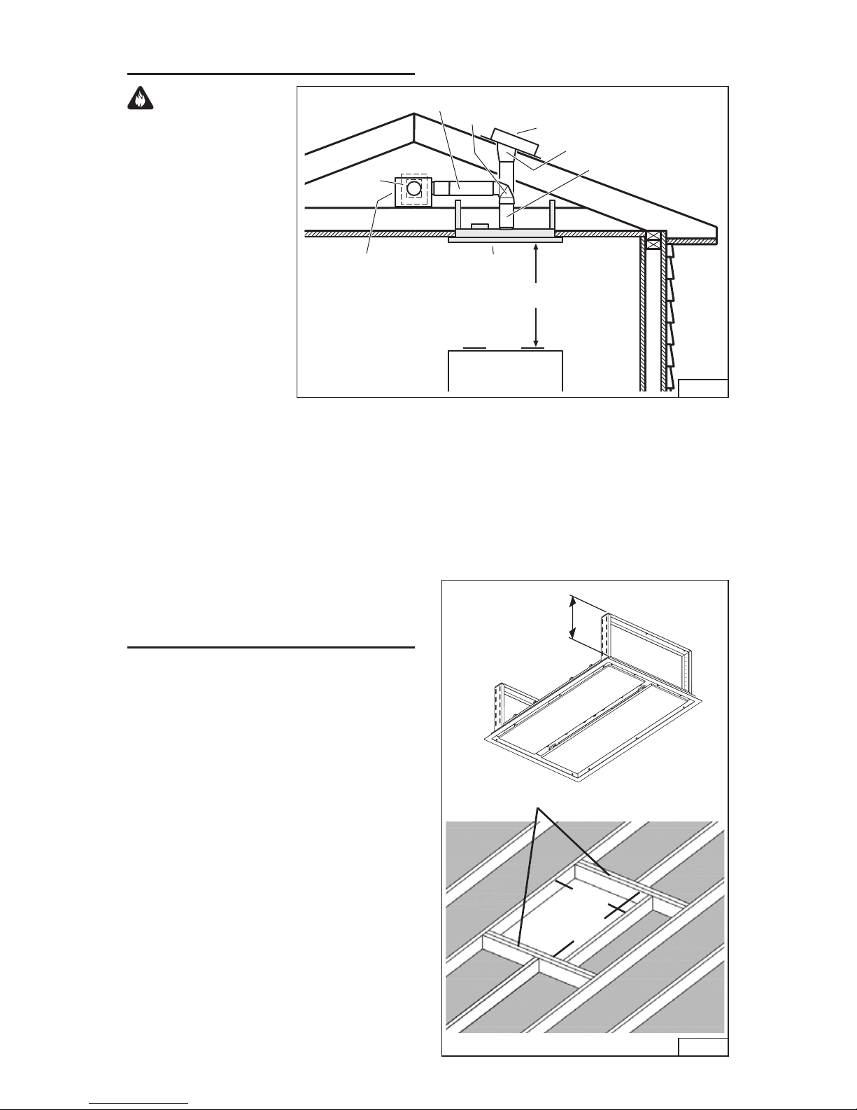
1. From the room interior, pull down both
closure panels. Fig. 9.
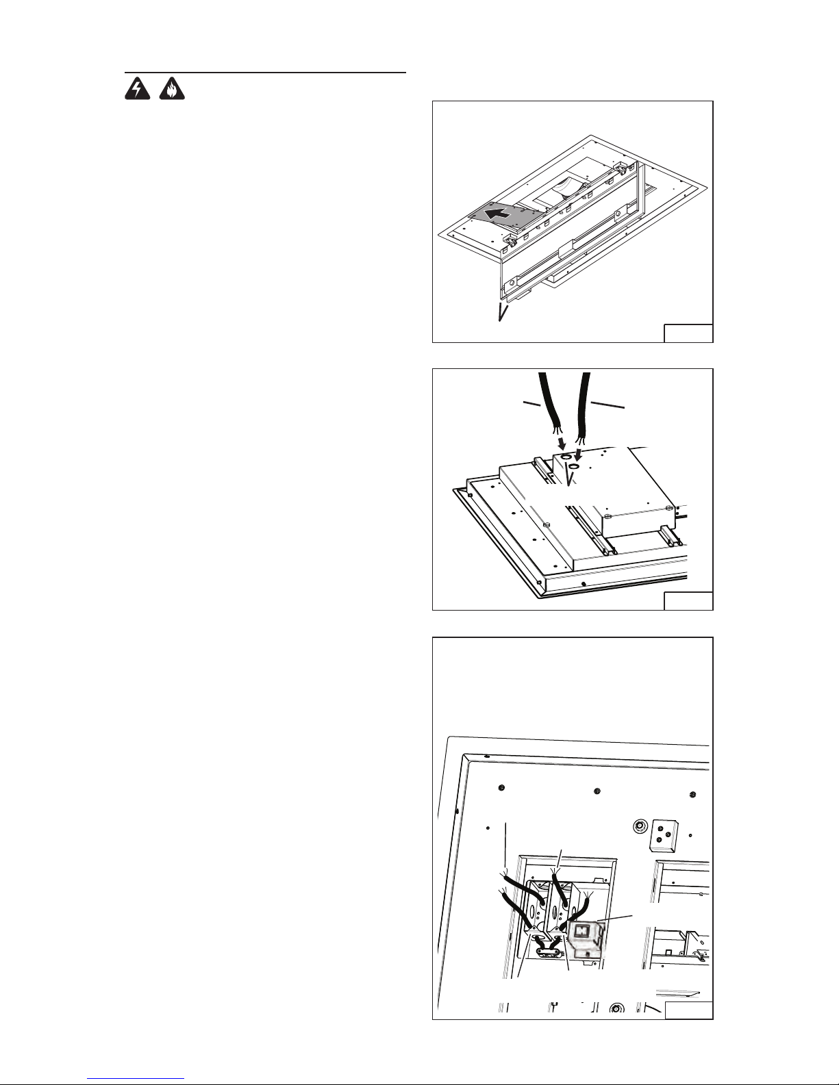
2. Remove (4) screws from the electrical
compartment access panel. Slide the panel
sideways to expose the electrical wiring box.
BLOWER CONNECTION AT THE HOOD
1. Run 2-wire plus ground power cable to a ¾”
knockout located on the back of the hood.
Fig. 10.
2. Remove a ¾” electrical knockout from the
back of the hood.
5. From the electrical box marked “MOTOR
CONNECTION”, remove (2) screws that
secure the cover to the metal wiring box.
Fig. 11.
6. Pull 6” of cable into the box and secure with
an appropriate cable clamp.
7. Make electrical connections inside the “MO-
TOR CONNECTION” box. Connect white-
to-white, red-to-black and green-to-ground.
8. Replace the wiring box cover and the
screws. Make sure wires are not pinched
between the cover and box.
CONNECTIONS AT EXTERIOR OR IN-LINE
BLOWER
1. Make electrical connections at the exterior
or in-line blower (see blower instructions).
BLOWER CONNECTION AT THE HOOD
1. Run 2-wire plus ground, 120 VAC electrical
power cable to a ¾” knockout located on the
back of the hood. Fig. 10.
2. Remove a ¾” electrical knockout from the
back of the hood.
3. From the electrical box marked “120VAC
INPUT”, remove (2) screws that secure the
cover to the metal wiring box. Fig. 11.
4. Pull 6” of cable into the box and secure with
an appropriate cable clamp.
5. Make electrical connections inside the
“120VAC INPUT” box. Connect white-to-
white, black-to-black and green-to-ground.
6. Replace the wiring box cover and the
screws. Make sure wires are not pinched
between the cover and box.
7. Replace the electrical compartments ac-
cess panel and (4) screws.
2-WIRE PLUS
GROUND
120 VAC
LINE IN
KNOCKOUTS
FIG. 9
FIG. 11
2-WIRE PLUS
GROUND
BLOWER
CONNECTION
CLOSURE PANELS
MAIN
SWITCH

- 11 -
INSTALL THE FILTERS
1. Pull down both closure panels as shown.
2. To install the grease filters, align rear filter
tabs with slots in the hood. Push latch tab
in, push filter into position and release.
Make sure filter is securely engaged after
installation. Fig. 12.
3. To remove the filters for cleaning, push
latch tab in to disengage filter from hood.
Tilt the filter downward and remove. Fig. 13.
FIG. 12
FIG. 13
PROGRAMMING MODE
PROCEDURE
The range hood is designed to work with
several different blower models. Before us-
ing, the control must first be programmed to
your blower model, in order to achieve proper
operating speeds.
From the chart below:
1. Find the SETUP number that corresponds
to the blower model that is installed with
your range hood.
2. The control is factory-preset to SETUP 3. If
your blower model is listed under SETUP
3, no programming is required. The range
hood is ready to use.
3. For blower models listed under SETUP 1
or 2 follow this program sequence:
A - Power at the service box must be ON
while programming. The blower and
lights must be turned off.
B - Press P2 for 3 seconds. The L1 LED
ring will flash at 3 different rates of
speed: slow flashing speed = SETUP
1; medium flashing speed = SETUP 2;
fastest flashing speed = SETUP 3 (the
factory-preset default).
C - To select the proper SETUP, press P3
(-) or P4 (+) to change to SETUP 1, 2
or 3.
D - Once the proper SETUP is found, press
P2 (f) to memorize the SETUP setting.
E - The range hood is now ready to use.
P1
P2
P3 P4
P1: Activate/deactivate delay-off (10 minute)
P2: Filter change indication timer reset
P3: Decreases fan motor speed until turned off (4>3>2>1>OFF)
P4: Turns fan motor on and increased speed (ON>1>2>3>4)
P5: Turns lights on/off
L1: LED Indicator Ring Signalling crown:
- Hood in standby: lights up green. 30 seconds after
the last key has been pressed the crown turns off
- Motor on: L1 lights up blue The
frequency is proportional to the speed setting.
- 10’ TIMER function : L1 lights up and flashes blue.
- Filter alarm active: L1 lights up red
L1
LED
RING
P5 +
-
ƒ
¤
SETUP 1 SETUP 2 SETUP 3 (default)
BLOWER
MODEL
NUMBER
EB6
ILB3
ILB6
EB12
ILB9
EB15 EB9
ILB11

- 12 -
WARRANTY
ONE YEAR LIMITED WARRANTY FOR BEST PRODUCTS
Broan-NuTone LLC (Broan-NuTone) warrants to the original consumer purchaser of Best products that such products
will be free from defects in materials or workmanship for a period of one year from the date of original purchase. THERE
ARE NO OTHER WARRANTIES, EXPRESS OR IMPLIED, INCLUDING, BUT NOT LIMITED TO, IMPLIED WARRAN-
TIES OR MERCHANT ABILITY OR FITNESS FOR A PARTICULAR PURPOSE.
During this one-year period, Broan-NuTone will, at its option, repair or replace, without charge, any product or part which
is found to be defective under normal use and service.
THIS WARRANTY DOES NOT EXTEND TO FLUORESCENT LAMP STARTERS, TUBES, HALOGEN AND INCANDES-
CENT BULBS, FUSE, FILTERS, DUCTS, ROOF CAPS, WALL CAPS AND OTHER ACCESSORIES FOR DUCTING.
This warranty does not cover (a) normal maintenance and service or (b) any products or parts which have been subject
to misuse, negligence, accident, improper maintenance or repair (other than by Broan-NuTone), faulty installation or
installation contrary to recommended installation instructions.
The duration of any implied warranty is limited to the one-year period as specified for the express warranty. Some states
do not allow limitation on how long an implied warranty lasts, so the above limitation may not apply to you.
BROAN-NUTONE’S OBLIGATION TO REPAIR OR REPLACE, AT BROAN-NUTONE’S OPTION, SHALL BE THE
PURCHASER’S SOLE AND EXCLUSIVE REMEDY UNDER THIS WARRANTY. BROAN-NUTONE SHALL NOT BE LI-
ABLE FOR INCIDENTAL, CONSEQUENTIAL OR SPECIAL DAMAGES ARISING OUT OF OR IN CONNECTION WITH
PRODUCT USE OR PERFORMANCE. Some states do not allow the exclusion or limitation of incidental or consequential
damages, so the above limitation or exclusion may not apply to you.
This warranty gives you specific legal rights, and you may also have other rights, which vary from state to state. This
warranty supersedes all prior warranties.
To qualify for warranty service, you must (a) notify Broan-NuTone at the address stated below or telephone number stated
below, (b) give the model number and part identification and (c) describe the nature of any defect in the product or part.
At the time of requesting warranty service, you must present evidence of the original purchase date.
In USA - Best®, 926 W. State Street, Hartford, WI 53027 (800-558-1711)
In Canada - Best®, 550 Lemire Blvd., Drummondville, QC J2C 7W9 (866-737-7770)
www.BestRangeHoods.com

- 13 -
SERVICE PARTS
KEY NO. PART NO. DESCRIPTION
1 B08092793 FRAME
9 B08087804 GREASE FILTER
16 BE3351504 ELECTRICAL BOX SUPPORT
22 FEEDER
38 B03295595 ELECTRICAL PRINTED CIRCUIT BOARD BOX
56 B08092517 CONNECTION AIR OUTLET
57 B02011341 DAMPER FLAP
62 BE3351505 BLOWER BRACKET
64 B03115251 BOTTON BRACKET
67 B02300995 WIRES
92 BE3350923 SWITCH BOARD BOX SUPPORT
107 B03202287 CABLE STOP
115 BE3350233 FEEDER CABLE CONNECTION BOX
116 FEEDER CABLE CONNECTION BOX COVER
124 BE3404989 BOTTOM TELESCOPIC SKELETON
125 B08092997 UPPER SUPPORT FRAME
166 B08080869 ELECTRICAL PRINTED CIRCUIT BOARD
167 B03295596 ELECTRICAL BOX COVER
223 B03293201 SWITCH BUTTON
228 B08080359 CONTROLS PRINTED CIRCUIT BOARD
230 B03293193 SWITCH BOARD BOX COVER
234 B03293400 SWITCH BOARD BOX
250 B02011389 RING NUT
282 BE3404224 MAIN SWITCH SUPPORT
283 B02300907 MAIN SWITCH
343 B08092798 CLOSURE PANEL
362 B02011421 DISPLAY VISOR SPRING
415 B03292596 FAIRLEAD
415 B03202288 FAIRLEAD
474 B02300885 HALOGEN LAMP
477
B02011376
CLOSING
998 B080810962 FITTING SET
999 B080813576 INSTALLATION INSTRUCTIONS SET
- B08092501 CONNECTION AIR OUTLET
(INCLUDES KEY No. 56, 57)
- B06145168 ELECTRICAL INSTALLATION ASSEMBLY
(INCLUDES KEY No. 22, 38, 166, 167, 208, 282, 283)
- B06103842 SWITCH BOX ASSEMBLY
(INCLUDES KEY No. 223, 228, 230, 234)
- B08999140 REMOTE CONTROL (COMPLETE)
Model CC34E6SB
B02300998
67 WIRES
B02300999
BE3351530

- 14 -
SERVICE PARTS
Model CC34E6SB
16
116
125
124
62
474
477
343
250
9
166
230
228
234
223
AQI
38
115
22
167
107
1
64
362
415 (03292596)
415 (03202288)
282
283
56
57
67 (02300995)
92
67 (02300999)

Modèle CC34E6SB
ENGLISH.....................................2
FRANÇAIS.................................15
ESPAÑOL.................................. 29
Aux ÉTATS-UNIS - BEST Hartford, Wisconsin
Au CANADA - BEST Drummondville, QC, Canada
ENREGISTREZ VOTRE PRODUIT EN LIGNE À : www.BestRangeHoods.com/register
Pour de plus amples informations, visitez www.BestRangeHoods.com

- 16 -
LIRE CES DIRECTIVES ET LES CONSERVER
AVERTISSEMENT
OBSERVEZ LES DIRECTIVES CI-DESSOUS AFIN DE RÉDUIRE LES RISQUES D’INCENDIE,
DE CHOC ÉLECTRIQUE OU DE BLESSURES CORPORELLES :
1. N’utilisez cet appareil que de la manière prévue par le fabricant. Si vous avez des questions,
communiquez avec le fabricant à l’adresse ou au numéro de téléphone indiqués dans la garantie.
2. Avant de procéder à la réparation ou à l’entretien de l’appareil, coupez l’alimentation du panneau
électrique et verrouillez l’interrupteur principal afin d’empêcher que le courant ne soit accidentellement
rétabli. S’il est impossible de verrouiller l’interrupteur principal, fixez solidement un message
d’avertissement, par exemple une étiquette, sur le panneau électrique.
3. La pose de l’appareil et les travaux d’électricité doivent être effectués par des personnes qualifiées
conformément à la réglementation en vigueur, notamment les normes de la construction ayant trait à
la protection contre les incendies.
4. Pour éviter les refoulements, l’apport d’air doit être suffisant pour brûler les gaz produits par les appareils
à combustion et les évacuer dans le conduit de fumée (cheminée). Respectez les directives du fabricant
de l’appareil de chauffage et les normes de sécurité, notamment celles publiées par la National Fire
Protection Association (NFPA), l’American Society for Heating, Refrigeration and Air Conditioning
Engineers (ASHRAE) et les codes des autorités locales.
5. Veillez à ne pas endommager le câblage électrique ou d’autres équipements non apparents lors de la
découpe ou du perçage du mur ou du plafond.
6. Les ventilateurs canalisés doivent toujours rejeter l’air à l’extérieur.
7. N’utilisez pas de commande de régime à semi-conducteurs conjointement avec cet appareil.
8. Pour réduire les risques d’incendie, utilisez seulement des conduits en métal.
9. Cet appareil doit être relié à une mise à la terre.
POUR RÉDUIRE LES RISQUES D’INCENDIE CAUSÉS PAR DE LA GRAISSE SUR LE PLAN
DE CUISSON :
A. Ne laissez jamais les éléments de surface allumés à haute température. Les débordements peuvent
causer de la fumée et occasionner des écoulements de graisse inflammables. L’huile doit être chauffée
graduellement à basse ou à moyenne température.
B. Mettez toujours la hotte en MARCHE lors de la cuisson à feu vif ou lors de la cuisson d’aliments
à flamber (crêpes Suzette, cerises jubilé, bœuf au poivre flambé).
C. Nettoyez souvent la hotte. Ne laissez pas la graisse s’accumuler sur le ventilateur ou les filtres.
D. Utilisez des casseroles de dimension appropriée. Utilisez toujours une batterie de cuisine adaptée à la
dimension de la surface chauffante.
OBSERVEZ LES CONSIGNES SUIVANTES DE MANIÈRE À RÉDUIRE LES RISQUES DE
BLESSURES CORPORELLES EN CAS D’INCENDIE CAUSÉ PAR DE LA GRAISSE SUR LE
PLAN DE CUISSON :*
1. ÉTOUFFEZ LES FLAMMES à l’aide d’un couvercle étanche, d’une tôle à biscuits ou d’un plateau en
métal puis éteignez le brûleur. FAITES ATTENTION DE NE PAS VOUS BRÛLER. Si les flammes ne
s’éteignent pas immédiatement, QUITTEZ LES LIEUX ET APPELEZ LE SERVICE DES INCENDIES.
2. NE SOULEVEZ JAMAIS UNE CASSEROLE EN FLAMMES - vous pourriez vous brûler.
3. N’UTILISEZ PAS D’EAU, ni de serviettes ou de linges mouillés – une violente explosion de vapeur
pourrait survenir.
4. Utilisez un extincteur SEULEMENT si :
A. Vous savez qu’il est de classe ABC et vous connaissez déjà son mode de fonctionnement.
B. L’incendie n’est pas très important et ne se propage pas.
C. Les pompiers ont été avisés.
D. Vous pouvez combattre l’incendie en faisant dos à une sortie.
* Conseils tirés de la publication de la NFPA « Kitchen Fire Safety Tips ».
!
POUR USAGE DOMESTIQUE SEULEMENT
!

- 17 -
!
ATTENTION
1. Pour usage intérieur seulement.
2. Pour réduire les risques d’incendie et évacuer l’air correctement, assurez-vous qu’il est canalisé à
l’extérieur. N’évacuez pas l’air dans des espaces enfermés par des murs ou un plafond ou dans un
grenier, un vide sanitaire ou un garage.
3. Faites attention lorsque vous utilisez des agents nettoyants ou des détergents.
4. Évitez d’utiliser des produits alimentaires pouvant produire des flammes sous la hotte.
5. Pour ventilation générale uniquement. N’évacuez pas cet appareil pour évacuer des matières ou des
vapeurs dangereuses ou explosives.
6. Pour éviter d’endommager les roulements de moteur, de déséquilibrer les pales ou de les rendre
bruyantes, débarrassez l’appareil de la poussière de plâtre, de construction, etc.
7. Le moteur de la hotte est muni d’un dispositif de protection de surcharge électrique qui coupe
automatiquement le moteur en cas de surchauffe. Il se remet en marche lorsqu’il a refroidi. Faites
réparer la hotte si le moteur continue à fonctionner par intermittence.
8. Pour mieux capter les vapeurs de cuisson, le bas de la hotte doit être au minimum à 122 cm (48 po)
et au maximum à 183 cm (72 po) de la surface de cuisson.
9. Il est recommandé d’avoir deux installateurs, compte tenu de la taille et du poids de cette hotte.
10. La source d’éclairage est conçue pour cette application particulière et peut surchauffer si elle est
réparée par un personnel sans formation. Si une réparation est nécessaire, le produit doit être retourné
à un centre de service agréé pour être examiné ou réparé.
11. Veuillez lire l’étiquette de spécifications du produit pour obtenir plus de renseignements, notamment
sur les exigences.
12. Pour réduire les risques d’incendie ou de choc électrique, installez cette hotte uniquement avec
lesmodèles de ventilateur extérieur Best EB6, EB9, EB12 ou EB15, ou les modèles de ventilateur
intermédiareBest ILB3, ILB6, ILB9 ou ILB11. Aucun autre ventilateur ne peut être substitué (Ventilateur
vendu séparément).

- 18 -
FONCTIONNEMENT
Commandes (Fig. 1)
La hotte fonctionne à l’aide de cinq (5) boutons-poussoirs situés sur la hotte et avec la télécommande.
Couleurs de LED sont affichés sur le contrôle hotte uniquement.
FIG. 1
(P1) Interrupteur d’arrêt différé
• Votre hotte comprend un interrupteur pour l’arrêt différé de 10 minutes. Appuyez une fois pour activer
la minuterie d’arrêt différé et l’anneau DEL (L1) se met à clignoter en bleu. Le ventilateur continuera de
fonctionner pendant 10 minutes. Après 10 minutes, le ventilateur s’arrête automatiquement.
• Pour annuler l’arrêt différé, appuyez de nouveau sur l’interrupteur.
(P2) Interrupteur d’alarme de filtre
• Après 30 heures de fonctionnement du ventilateur, l’alarme de filtre s’active et l’anneau DEL (L1) se met
à clignoter en rouge. Cela indique que les filtres à graisses doivent être nettoyés.
• Une fois ceux-ci nettoyés, appuyez sur le bouton de remise à zéro de l’indicateur de changement de
filtre (P2) pendant l’affichage de l’alarme.
(P3) Bouton de réduction de la vitesse du ventilateur et d’arrêt
• Appuyez pour réduire la vitesse du ventilateur. La vitesse de clignotement de l’anneau DEL (L1) en
bleu est fonction du réglage choisi (par ex. : quatre clignotements correspondent au régime maximal,
un clignotement au régime lent, etc.)
• Pour arrêter le ventilateur, continuez d’appuyer sur l’interrupteur.
(P4) Bouton de mise en marche et d’augmentation de la vitesse du ventilateur
• Appuyez une fois pour mettre le ventilateur en marche au régime le plus lent.
• Appuyez de nouveau pour augmenter le régime du ventilateur. La vitesse de clignotement de l’anneau
DEL (L1) en bleu est fonction du réglage choisi (par ex. : quatre clignotements correspondent au régime
maximal, un clignotement au régime lent, etc.)
(P5) Interrupteur d’éclairage
Il allume et éteint l’éclairage.
Maître interrupteur On-Off
Situé derrière l’un des filtres d’angle, ce commutateur doit être sur ON (indiquée comme “I”) avant de la
hotte fonctionner. Éteignez le commutateur (indiquée comme “O”) pour couper l’alimentation de la cagoule.
P1
P2
P3 P4
ANNEAU
DEL L1
P5 +
-
ƒ
¤
P1 : Activer/désactiver l’arrêt différé (10 minutes)
P2 : Remise à zéro de l’indicateur de changement de filtre
P3 : Réduit la vitesse du ventilateur jusqu’à son arrêt
(4>3>2>1>ARRÊT)
P4 : Actionne le ventilateur et augmente sa vitesse
(MARCHE>1>2>3>4)
P5 : Allume/éteint l’éclairage.
L1 : Anneau d’indicateur DEL :
- Hotte en veilleuse : s’allume de couleur verte. S’éteint 30
secondes après que l’on ait appuyé sur une touche
- Moteur en marche : L1 clignote en bleu. La rapidité du
clignotement est fonction de réglage de la vitesse.
- Délai différé de 10 minutes : L1 s’allume et clignote en bleu
- Alarme de filtre activée : L1 s’allume en rouge

- 19 -
NETTOYAGE ET ENTRETIEN
Un entretien adéquat de la hotte assurera son bon fonctionnement.
Moteur
Le moteur est lubrifié en permanence et n’a pas besoin d’être huilé. Si les roulements du moteur sont anormalement
bruyants, remplacez le moteur exactement par le même modèle. La roue à ailettes doit aussi être remplacée.
Filtres à graisses
Les filtres à graisses doivent être nettoyés fréquemment. Utilisez une solution tiède de détergent. Ces filtres sont
lavables au lave-vaisselle.
Nettoyez les filtres entièrement métalliques au lave-vaisselle avec un détergent sans phosphate. Une décoloration du
filtre peut se produire si des détergents phosphatés sont utilisés et selon les conditions locales de l’eau, sans toutefois
affecter le rendement du filtre. Cette décoloration n’est pas couverte par la garantie.
Voir la section « INSTALLATION DES FILTRES » pour leur enlèvement et leur pose.
Nettoyage de l’acier inoxydable
À FAIRE :
• Régulièrement, nettoyez toutes les surfaces avec un
chiffon propre imbibé d’eau tiède et de savon doux
ou de liquide à vaisselle.
• Nettoyez toujours dans le sens des lignes du poli
original.
• Rincez toujours à l’eau propre (2 ou 3 fois) après le
nettoyage. Séchez complètement en essuyant.
• Vous pouvez également utiliser un nettoyant spécial
pour acier inoxydable.
À NE PAS FAIRE :
•
N’utilisez pas de laine d’acier ordinaire ni de laine
d’acier inoxydable ou tout genre de grattoir pour
déloger la saleté.
• N’utilisez aucun nettoyant puissant ou abrasif.
• Ne laissez pas la saleté s’accumuler.
• Ne laissez pas la poussière de plâtre ou tout autre
résidu de construction pénétrer dans la hotte. Pendant
des travaux de construction ou de rénovation, couvrez
la hotte pour empêcher la poussière d’adhérer aux
surfaces d’acier inoxydable.
À éviter : lors du choix d’un détergent
• Tout nettoyant contenant de l’eau de javel attaquera l’acier inoxydable.
• Tout produit contenant : du chlore, du fluor, de l’iode ou du brome détériorera rapidement les surfaces.
• Tout produit combustible utilisé pour le nettoyage comme l’acétone, l’alcool, l’éther, le benzol, etc., est hautement
explosif et ne doit jamais être utilisé à proximité d’une hotte.

- 20 -
PRÉPARATION
DE LA HOTTE
Déballez la hotte et vérifiez le contenu de la boîte.
Celle-ci doit contenir les éléments suivants :
1 - Boîtier de hotte
1 - Télécommande
6 - Filtres à graisses
6 - Tire-fonds, 6 x 70 mm
6 - Rondelles
6 TIRE-FONDS
(6 x 70 mm)
FIG. 2
TÉLÉCOMMANDE
BOÎTIER DE
LA HOTTE 6 FILTRES À
GRAISSES
6 RONDELLES
SÉLECTION D’UN
VENTILATEUR EXTÉRIEUR
OU INTERMÉDIAIRE
Le ventilateur doit être homologué cULus pour
être utilisé au Canada ou aux États-Unis, et
évalué avec une commande de régime à semi-
conducteurs de 120V, 60Hz, 6.0A max.
ATTENTION: Un ventilateur extérieur ou
intermédiaire peut être utilisé avec cette
hotte. Le modèle de hotte CC34E6SB ne peut
être installé qu’avec les modèles de
ventilateur extérieur Best EB6, EB9, EB12
ou EB15 les modèles des ventilateur
intermédiaire Best ILB3, ILB6, ILB9 ou ILB11.
Aucun autre ventilateur ne peut être
substitué. (Ventilateur vendu séparément).
Other manuals for CC34E6SB
1
Table of contents
Languages:
Other Best Ventilation Hood manuals

Best
Best IS241 User manual

Best
Best CP55IQ series User manual

Best
Best WC43I80 User manual

Best
Best IM32I100SP User manual

Best
Best PKEX2238SS User manual

Best
Best WC26E Series User manual

Best
Best CP35 Series User manual

Best
Best IPP9 User manual

Best
Best Ispira WCB3I30SBS User manual

Best
Best WT32I SERIES User manual