Stancor SEW Series User manual

EI-700-006 REV 1
Installation,
Operation
and Maintenance
Manual
Stancor™
SEW Series
Pumps
_______________________________________________________________________

2
READ THESE INSTRUCTIONS CAREFULLY BEFORE ATTEMPTING TO INSTALL, OPERATE, OR SERVICE YOUR
PRODUCT.
KNOW THE PRODUCT’S APPLICATION, LIMITATIONS, AND POTENTIAL HAZARDS. PROTECT YOUR-SELF AND
OTHERS BY OBSERVING ALL SAFETY INFORMATION. FAILURE TO COMPLY WITH THESE INSTRUCTIONS COULD
RESULT IN PERSONAL INJURY AND/OR PROPERTY DAMAGE!
WARNING: RISK OF ELECTRIC SHOCK.
Safety Guidelines
This instruction manual provides you with the information required to safely own and operate your
product. Retain these instructions for future reference.
The product you have purchased is of the highest quality workmanship and material and has been engineered to give
you long and reliable service.
This product has been carefully tested, inspected, and packaged to ensure safe delivery and operation. Please examine
your item(s) carefully to ensure that no damage occurred during shipment.
If damage has occurred, please contact the place of purchase. They will assist you in replacement or repair, if required.
To reduce the risk of electric shock, be certain that it is connected only to a properly grounded, grounding type
receptacle.
When a pump is in a basin, etc., do not touch motor, pipes or water until unit is unplugged or shut off. If your
installation has water or moisture present, do not touch wet area until all power has been turned off. If shut-off box is
not accessible, call the electric company to shut off service to the location, or call your local fire department for
instructions. Failure to follow this warning can result in fatal electrical shock.
The flexible jacketed cord assembly mounted to the pump must not be modified in any way, with the exception of
shortening the cord to fit into a control panel. Any splice between the pump and the control panel must be made within
a junction box and mounted outside of the basin and comply with the National Electrical Code. Do not use the power
cord for lifting the pump.
The pump motor is equipped with an automatic resetting thermal protector and may restart unexpectedly.
Protector tripping is an indication of motor overloading as a result of operating the pump at low heads (low
discharge restriction), excessively high or low voltage, inadequate wiring, incorrect motor connections, or a
defective motor or pump.
For a submersible well pump:
Reduced risk of electric shock during operation of this pump requires the provision of acceptable grounding:
When the means of connection to the supply-connection box is other than grounded metal conduit, ground the
pump back to the service by connecting a copper conductor, at least the size of the circuit conductors supplying
the pump, to the grounding screw provided within the wiring compartment.
This pump is provided with a means for grounding. To reduce the risk of electric shock from contact with adjacent
metal parts, bond supply box to the pump-motor-grounding means and to all metal parts accessible at the well
head, including metal discharge pipes, metal well casing, and similar parts, by means of:
•An equipment-grounding conductor at least the size of the well-cable conductors or the equivalent, that
runs down the well with the well cable and
•A clamp, a weld, or both when required, secured to the equipment-grounding lead, the equipment-
grounding terminal, or the grounding conductor on the pump housing.
•The equipment-grounding lead, when one is provided, is the conductor that has an outer surface of
insulation that is green with or without one or more yellow stripes.

3
For a cord and plug-connected pump:
Risk of electric shock - This pump is supplied with a grounding conductor and grounding-type attachment plug. To
reduce the risk of electric shock, be certain that it is connected only to a proper grounded, grounding type
receptacle.
When use as a fountain pump, to reduce the risk of electric shock, use only on portable self-contained fountains
no larger than 5 feet in any dimension. Read all instructions and Safety Guidelines thoroughly. Failure to follow
the guidelines and instructions could result in serious bodily injury and/or property damage.
During normal operation, this pump is immersed in water. Also, during rainstorms, water may be present in the
surrounding area of the pump.
Caution must be used to prevent bodily injury when working near the pump. Electrical power should be disconnected
prior to touching, servicing or repairing the pump.
Do not run the pump in a dry basin. If the pump is run in a dry basin, the surface temperature of the
pump will rise to a high level. This high temperature could cause skin burns if the pump is touched
and will cause serious damage to your pump.
Do not install in locations classified as hazardous in accordance with the National Electrical Code,
ANSI/NFPA 70.
Do not remove cord and strain relief. Do no connect conduit to pump.
DO NOT USE TO PUMP FLAMMABLE OR EXPLOSIVE FLUIDS SUCH AS GASOLINE, FUEL OIL, KEROSENE, ETC.
FAILURE TO FOLLOW THIS WARNING CAN RESULT IN PERSONAL INJURY, DEATH AND/OR PROPERTY DAMAGE.

4
Instruction Manual
2.5" & 3" Full-Passage Submersible Pump
SEW DN65/80 SERIES
INDEX
Introduction… ..............PAGE. 4
Spécifications………….PAGE. 4
Installation…….……....PAGE. 5
Electrical wiring………..PAGE. 5
Operation………..….….PAGE. 6
Maintenance…………...PAGE. 6
Construction (SEW DN 1.5~2HP)……PAGE. 7
Construction (SEW DN 3HP)… .......... PAGE. 9
Disassembly and Assembly…………..PAGE. 11
Nameplate format………………………PAGE. 11
Troubleshooting…………………….…..PAGE. 12
Introduction
Check the following points upon receipt of your pump:
>
Is the pump exactly what you ordered? Check nameplate. It is especially important that you check
whether the pump is to be used with 50 or 60 Hz.
>
Has any damage occurred during shipment? Are any bolts or nuts loose?
>
Have all necessary accessories been supplied?
(For a list of standard accessories see
Construction.)
We recommend that you keep a spare pump on hand in case of emergencies.
Keep this instruction manual in a place for future reference.
Specifications
Check the nameplate for your pump’s head, discharge volume, speed (R.P.M), motor voltage
and current.
Other specifications are noted in the chart below.
Item
Specifications
Liquid handled
Type
Sewage, wastewater, miscellaneous drain water
Temperature
Non-Automation
1.5~3 HP
0~40℃ (32~104°F)
Automation
1.5~2
HP
0~40℃ (32~104°F)
Materials
Casing
FC 200
Impeller
FC 200
Shaft SUS410 stainless steel
Motor type
Dry type submersible motor
Shaft seal lubrication oil
Turbine No.32 ISO VG-32
Maximum water depth
10m (33ft)

5
Installation
1.
Check the following before beginning installation.
Insulation resistance measurement:
With the motor and cable (excluding the power supply cable) immersed in water, use a Megger to measure the insulation
resistance between ground and each phase of the motor, and again between each phase of the motor. The Megger should
indicate an insulation resistance of not less than 20mega ohms. While making the measurement, keep the power supply
cable off the ground.
We recommend that an auxiliary pump be kept on hand in case of emergency.
2.
Installation
1. ! WARNING: Under no circumstances should cable be
pulled while the pump is being transported or installed.
Attach a chain or rope to the grip and install the pump.
2. This pump must not be installed on its side or operated a
dry condition. Ensure that it is installed upright on a
secure base.
3.Install the pump at a location in the tank where there is
the least turbulence.
4.If there is a flow of liquid inside the tank, support the
piping where appropriate.
5. Install piping so that air will not be entrapped. If piping
must be installed in such a way that air pockets are un-
avoidable, install an air release valve wherever such air
pockets are most likely to develop.
6.
Do not permit end of discharge piping to besubmerged,
as backflow will result when the pump is shut down.
7. ! WARNING: Non-automatic pumps do not have an
automatic operating system. Do not operate the pump for
a long time with the water level near the lowest water
level(H1) as shown in Fig.1, as the automatic cut-off
switch incorporated inside the motor will be activated.
8.To avoid dry operation, install an automatic operating
system so that this will not happen, as shown in Fig.2
and maintain a safe operating water level.
Electrical wiring
1.Wiring
A. Wire as indicated for the appropriate start system as
shown in Fig-3.
B. Loose connections will stop the pump. Make sure all
electrical connections secure.
2. Cable
C. ! WARNING: Never let the end of the cable con-
tact water.
D. If the cable is extended, do not immerse the splice
in water.
E. Fasten the cable to the discharge piping with tape or
vinyl strips.
F. Install the cable so that it will not overheat. Over-
heating caused by coiling the cable and exposing it
to direct sunlight.
3. Grounding
As shown in Fig-4 ground the green wire (label E).
Under no circumstances should the green wire be
connected to the power supply.
4. ! WARNING: Use short circuit breakers to prevent
danger of electrical shock.
H1: Lowest water level (Motor flange)
H2: Operating water level
This must be above the top of the motor
Operating Water Level
Stop Water Level
Fig-2
Fig-3
Fig-4
on
off
Fig-1
H2
H1
6
Operation
1.
Before starting the pump
a. After completing installation, measure the insulation resistance again as described in Installation.
b. Check water level.
If the pump is operated continuously for an extended period of time in a dry condition or at the lowest water
level, the motor protector will be activated. Constant repetition of this action will shorten pump service life. Do
not start the pump again in such a situation until after the motor has completely cooled.
2.
Test operation….
Non-automatic pump
Automatic pump
a. Turn the operating switch on and off a couple of times to check for normal pump start.
Floating switch must be raised for the pump to start.
b. Next, check direction of rotation. If discharge volume is low or unusual sounds are heard when the pump is
operating, rotation has been reversed. When this happens, reverse two of the wires.
Maintenance
Check pressure, output, voltage, current and other specifications. Unusual readings may indicate.
Refer to Troubleshooting and correct as soon as possible.
1. Daily inspections
Check current and ammeter fluctuation daily. If ammeter fluctuation is great, even though within the limits of pump
rating, foreign matter may be clogging the pump. If the quantity of liquid discharged falls suddenly, foreign matter
may be blocking the suction inlet.
2. Regular inspections
Monthly inspections
Measure the insulation resistance. The value should be more than 1M ohm. If resistance starts to fall rapidly even
with an initial indication of over 1M ohm, this may be an indication of trouble and repair work is required.
Annual inspections
To prolong the service life of the mechanical seal by replacing the oil in the mechanical seal chamber once a year.
Water mixed the oil or cloudy textures are indications of a defective mechanical seal requiring replacement. When
replacing the oil, lay the pump on its side with filler plug on top. Inject suitable amount turbine oil No.32 (ISO VG-32)
.
Inspections at 3-5year intervals
Conduct an overhaul of the pump. These intervals will preclude the possibility of future trouble.
3. Parts that will need to be replaced
Replace the appropriate part when the following conditions are apparent.
Replaceable part
Mechanical seal
Oil filler plug O-ring
Lubricating oil
O-ring
Replacement guide
Whenever oil in
mechanical seal
chamber is clouded
Whenever oil is replaced
or inspected
Whenever clouded or dirty Whenever pump is
overhauled
Frequency Annually A half yearly A half yearly Annually
Note: above replacement schedule is based on normal operating conditions.
Motor output 1.5HP 2HP 3HP
Mechanical seal 15Ø
Oil seal 15Øx 24Øx 7 t
Oil filler plug O-ring (Inner diameter) x (outer diameter) x (thickness) = 7.52Øx14.5Øx3.53 t
Lubricating oil
(turbine oil #32) 280 cc
7
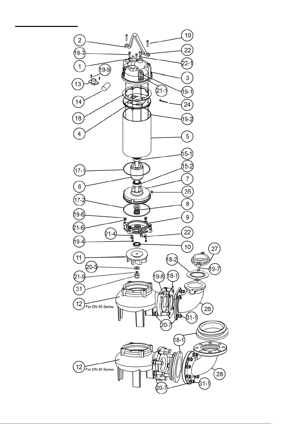
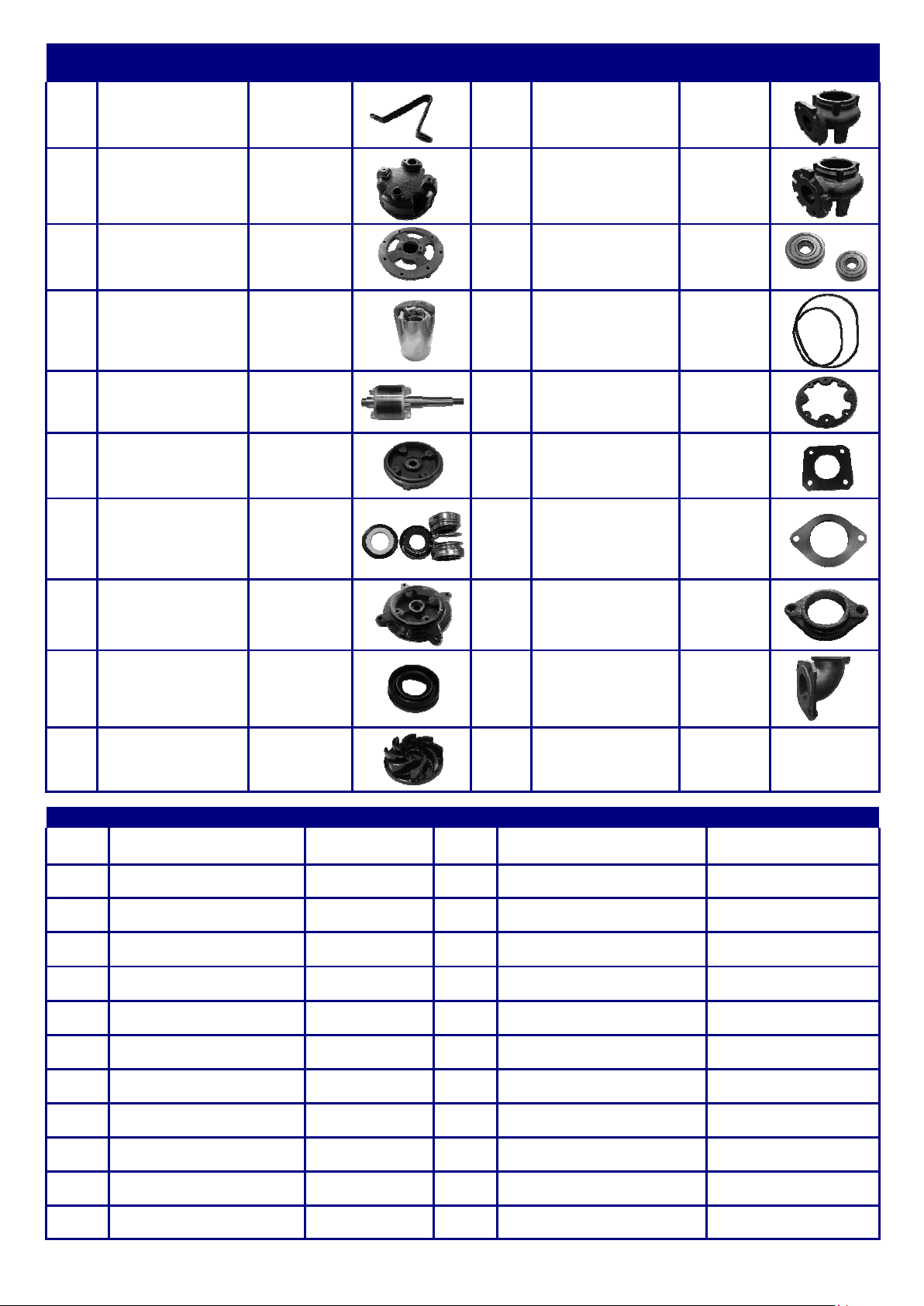
Construction
SEW DN 1.5~2HP
8
NO Name Mtrl Photo NO Name Mtrl Photo
2
Handle
SS41
12 Pump Casing
(DN65)
FC 200
3
Motor
Cover
FC 200
12 Pump Casing
(DN80)
FC 200
4
Bracket
FC 200
15
Bearings
5
Motor Housing
+Stator
SUS 304
17
O-rings
NBR
6
Shaft with Rotor
SUS 410
18
Gasket
NBR
7
Oil Chamber
FC 200
18-1
Elbow Gasket
NBR
8
Double Mech.
Seal
CA/CE
+
SIC/SIC
18-2
Flange Packing
NBR
9
Seal Housing
FC 200
27
Flange
FC 200
10
Oil Seal
NBR
28
Elbow
FC 200
11
Impeller
FC 200
NO
Name
Mtrl
NO
Name
Mtrl
1 Cable
H07RN-F/
SJTOW/STOW
20-5 Washer SUS 304
13 Protector (3 Phase)
20-7 Washer SUS 304
14 Capacitor (1 Phase)
21-1 Spring Washer SUS 304
19 Screw SUS 304 21-4 Washer with O-ring SUS 304+NBR
19-1 Screw SUS 304 21-6 Spring Washer SUS 304
19-2 Long Screw of motor Steel 21-9 Spring Washer SUS 304
19-3 Screw SUS 304 22 Oil Filler Plug SUS 304
19-4 Screw SUS 304 22-1 O-ring of Oil Filler Plug NBR
19-6 Screw SUS 304 24 Wire and Screw SUS 304
19-7 Screw SUS 304 31 Nut of impeller SUS 304
19-8 Screw SUS 304 31-1 Nut of Elbow SUS 304
19-9 Screw SUS 304 35 Key SUS 304

9
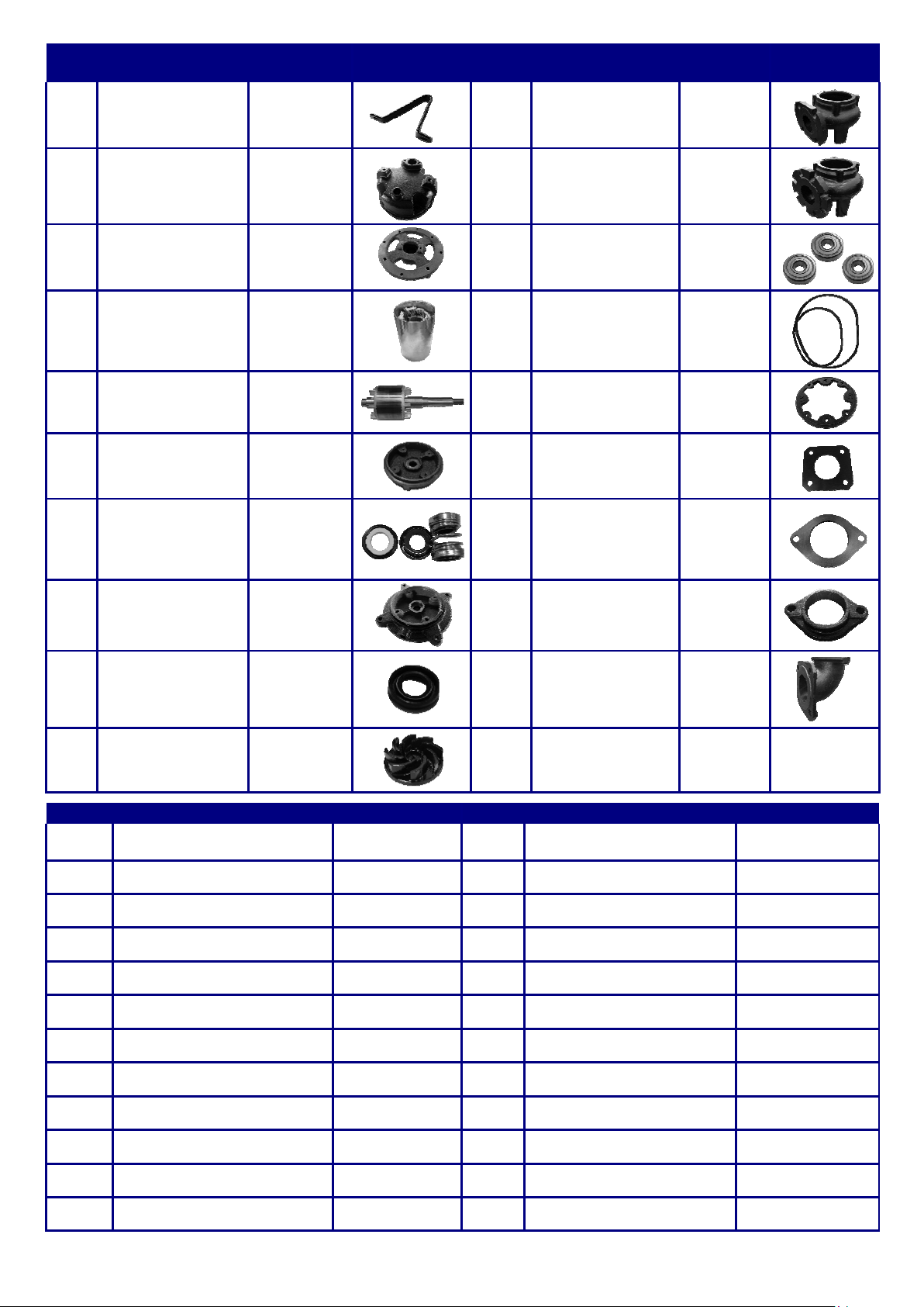
Construction
SEW DN 3HP
10
NO Name Mtrl Photo NO Name Mtrl Photo
2
Handle
SS41
12 Pump Casing
(DN65)
FC 200
3
Motor
Cover
FC 200
12 Pump Casing
(DN80)
FC 200
4
Bracket
FC 200
15
Bearings
5
Motor Housing
+Stator
SUS 304
17
O-rings
NBR
6
Shaft with Rotor
SUS 410
18
Gasket
NBR
7
Oil Chamber
FC 200
18-1
Elbow Gasket
NBR
8
Double Mech.
Seal
CA/CE
+
SIC/SIC
18-2
Flange Packing
NBR
9
Seal Housing
FC 200
27
Flange
FC 200
10
Oil Seal
NBR
28
Elbow
FC 200
11
Impeller
FC 200
NO
Name
Mtrl
NO
Name
Mtrl
1 Cable
H07RN-F/
SJTOW/STOW
20-5 Washer SUS 304
13 Protector (3 Phase)
20-7 Washer SUS 304
14 Capacitor (1 Phase)
21-1 Spring Washer SUS 304
19 Screw SUS 304 21-4 Washer with O-ring SUS 304+NBR
19-1 Screw SUS 304 21-6 Spring Washer SUS 304
19-2 Long Screw of motor Steel 21-9 Spring Washer SUS 304
19-3 Screw SUS 304 22 Oil Filler Plug SUS 304
19-4 Screw SUS 304 22-1 O-ring of Oil Filler Plug NBR
19-6 Screw SUS 304 24 Wire and Screw SUS 304
19-7 Screw SUS 304 31 Nut of impeller SUS 304
19-8 Screw SUS 304 31-1 Nut of Elbow SUS 304
19-9 Screw SUS 304 35 Key SUS 304

11
Disassembly and Assembly
1.
Disassembly-
When disassembling pump, have a piece of cardboard or wooden board ready to place the different parts on as
you work. Do not pile parts on top of each other.
They should be laid out neatly in rows. The “O” ring and gasket cannot be used again
once they are removed. Have replacement parts ready. Disassemble in the following order, referring to the
sectional view.
Be sure to cut off power source before disassembly.
(1)
Remove pump casing bolts, raise the motor section and remove pump casing.
(2)
Remove shaft head bolt and impeller.
(3)
Remove oil filler plug and drain lubricating oil.
(4)
Remove intermediate casing bolts and oil chamber.
(Remember that any lubricating oil remaining in the mechanical seal chamber will flow out.)
(5)
Carefully remove mechanical seal, beware of not to scratch sliding surface of motor shaft.
2.
Assembly-
Re-assemble in reverse order of disassembly.
Be careful of the following points.
(a)
During re-assembly, rotate the impeller by hand and check for smooth rota- tion. If rotation is not smooth,
perform steps-(3) through -(5) again.
(b)
Upon completion of re-assembly step -(1) rotate the impeller by hand from the suction inlet and check that it
rotates smoothly without touching the suction cover before operating the pump.
Please order “O” rings, packing, shaft seals and other parts from your dealer.
Nameplate format

12
Troubleshooting
Trouble Cause Remedy
Does not start.
Starts, but imme-
diately stops.
(1) Power failure
(1) ~(3) Contact electric power company
and devise counter-measures
(2) Large discrepancy between power source and
voltage
(3) Significant drop in voltage
(4) Motor phase malfunction
(4) Inspect electric circuit
(5) Electric circuit connection faulty
(5) Correct wiring
(6) Faulty connection of control circuit
(6) Inspect connections and magnetic coil
(7) Fuses is blown
(7) Check circuit then replace fuse
(8) Faulty magnetic switch
(8) Replace with correct one
(9) Water is not at level indicated by Float
(9) Raise water level
(10) Float is not in appropriate level
(10) Adjust the position of float
(11) Float is not effective
(11) Repair or replace
(12) Short circuit breaker is functioning
(12) Repair location of short circuit
(13) Foreign matter clogging pump
(13) Remove foreign matter
(14) Motor burned out
(14) Repair or replace
(15) Motor bearing broken
(15) Repair or replace
Operates, but
stops after a
while.
(1) Prolonged dry operation has activated motor
protector and caused pump to stop
(1) Raise water level to C.W. L
(2) High liquid temperature has activated motor
protector and caused pump to stop
(2) Lower liquid temperature
(3) Reverse rotation
(3) Correct rotation
Does not pump.
Inadequate vol-
ume.
(1) Reverse rotation
(1) Correct rotation (see Operation)
(2) Significant drop in voltage
(2) Contact electric power company
(3) Operating a 60Hz pump with 50Hz
(3) Check nameplate
(4) Discharge head is high
(4) Recalculate and adjust
(5) Large piping loss
(5) Recalculate and adjust
(6) Low operating water level causes air suction
(6) Raise water level or lower pump
(7) Leaking from discharge piping
(7) Inspect, repair
(8) Clogging of discharge piping
(8) Remove foreign matter
(9) Foreign matter in suction inlet
(9) Remove foreign matter
(10) Foreign matter clogging pump
(10) Remove foreign matter
(11) Worn impeller
(11) Replace impeller
Over current
(1) Unbalanced current and voltage
(1) Contact electric power company
(2) Significant voltage drop
(2) Contact electric power company and de-
vise countermeasure
(3) Motor phase malfunction
(3) Inspect connections and magnetic switch
(4) Operating 50Hz pump on 60Hz
(4) Check nameplate
(5) Reverse rotation
(5) Correct rotation
(6) Low head. Excessive volume of water
(6) Replace pump with high head pump
(7) Foreign matter clogging pump
(7) Remove foreign matter
(8) Motor bearing is worn out or damaged
(8) Replace bearing
Pump vibrates;
excessive oper-
ating noise.
(1) Reverse rotation
(1) Correct rotation
(2) Pump clogged with foreign matter
(2) Disassemble and remove foreign matter
(3) Piping resonates
(3) Improve piping
(4) Strainer is closed too far
(4) Open strainer

13
Notes
Industrial Flow Solutions Operating, LLC • 104 John W Murphy Drive, New Haven, CT 06513, USA • 860-399-5937 • www.flowsolutions.com
Stancor™ is a trademark of Industrial Flow Solutions Operating, LLC. All rights reserved.
Table of contents
Other Stancor Water Pump manuals


Popular Water Pump manuals by other brands

Graco
Graco 970056 Instructions-parts list

Safe Fleet
Safe Fleet FoamPRO 1600 System Installation and operation manual

CountyLine
CountyLine CL3P owner's manual

Evolution Aqua
Evolution Aqua Varipump 10000 instruction manual

Liberty Pumps
Liberty Pumps HT40 Series installation manual

AquaCharge
AquaCharge AquaCharge owner's manual


KSB
KSB KWP-Bloc Installation & operating manual

BGS technic
BGS technic 4064 instruction manual

Clarke
Clarke EBP1100 Operation & maintenance instructions

NITTOH Power
NITTOH Power UP-40H Series Operation & maintenance manual

Grundfos
Grundfos DDA 7.5-16 Installation and operating instructions

KIRLOSKAR
KIRLOSKAR GK Series Instruction on installation, operation and maintenance