Standard IGL15 User manual

IGL15
Permanent magnet synchronous elevator traction machine
Product Operation and Maintenance Manual
S2018.05

IGL15 Spare parts replacement manual
Version:S2018.05 1
Catalogue
ATALOGUE............................................................................................................................................1
1. PREFACE.......................................................................................................................................2
1.1. SAFETY DECLARATION .............................................................................................................2
1.2. IGL15 TRACTION MACHINE SPARE PARTS LIST ..........................................................................2
2. SPARE PARTS REPLACEMENT OPERATION.......................................................................3
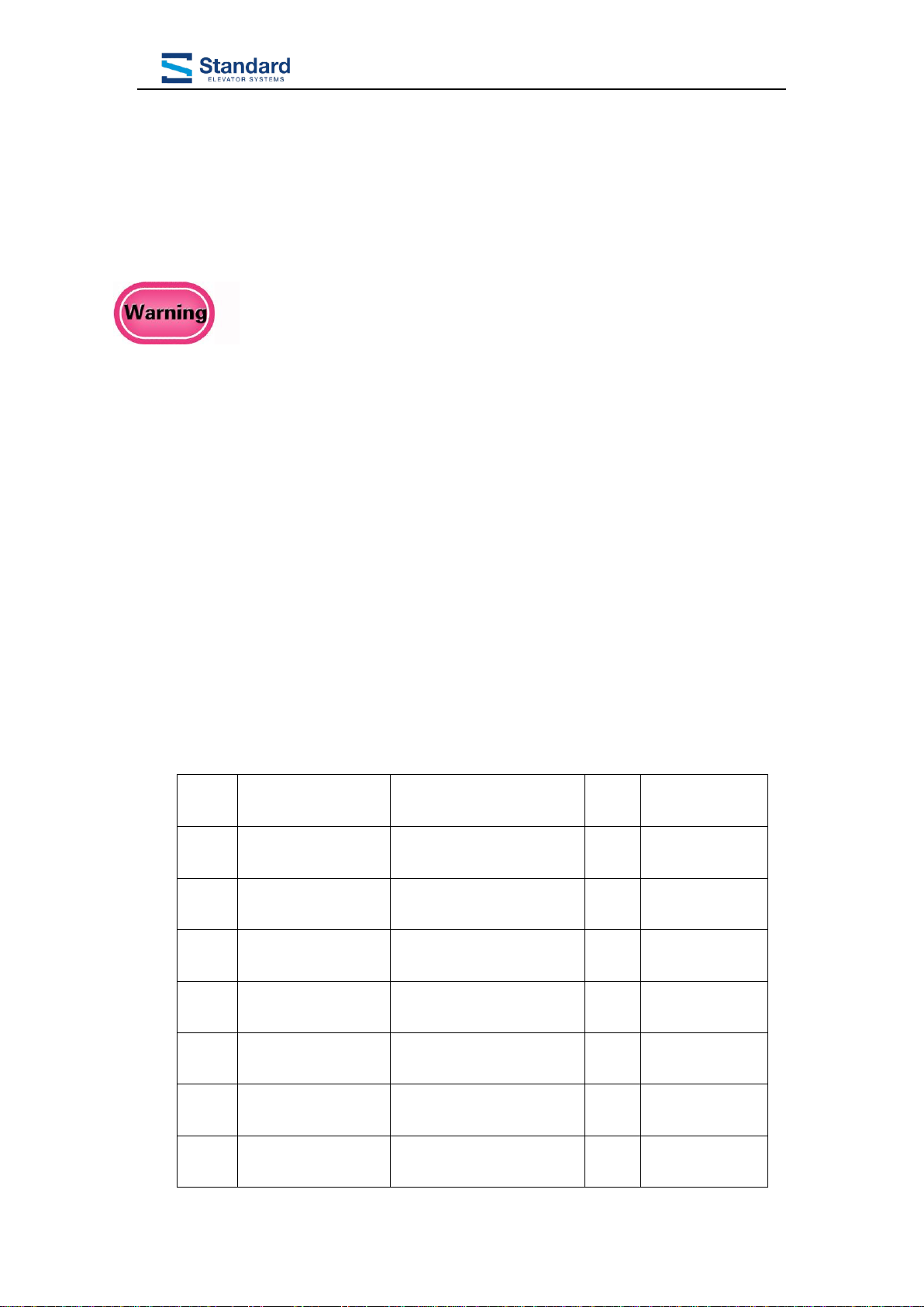
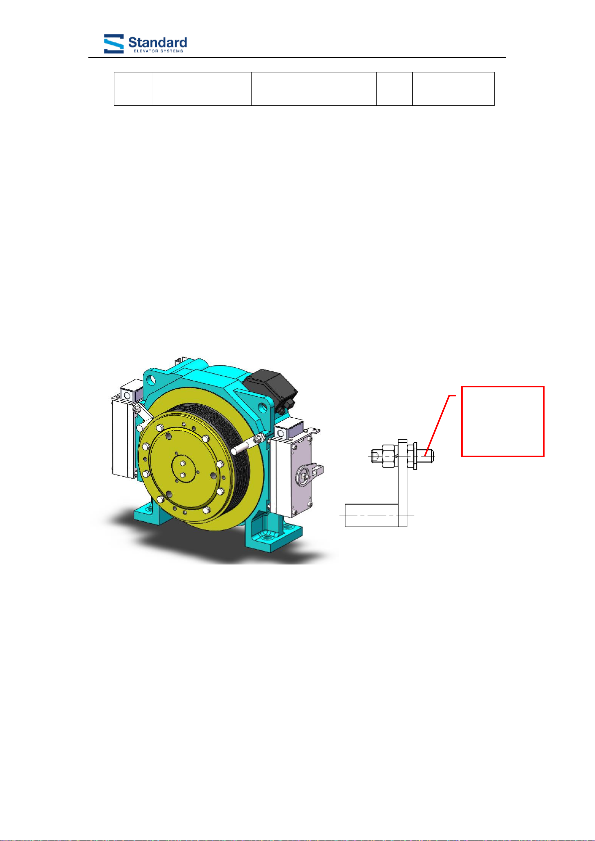
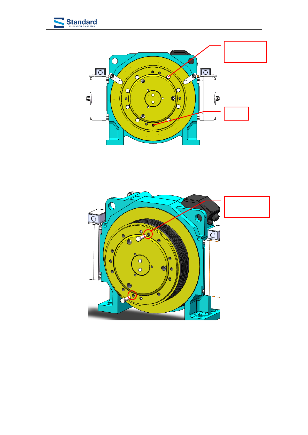
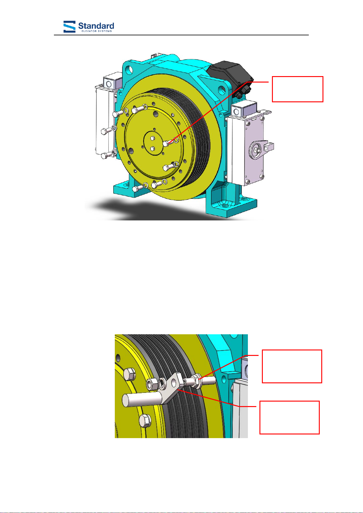
2.1. TRACTION WHEEL REPLACEMENT.............................................................................................3
2.1.1. Remove the traction sheave.............................................................................................3
2.1.2. Install the traction sheave ...............................................................................................5
2.2. ENCODER REPLACEMENT .........................................................................................................7
2.2.1. Remove the encoder ERN1387........................................................................................7
2.2.2. Install the encoder ERN1387...........................................................................................9
2.3. BEARING 6212-2RS REPLACEMENT .......................................................................................12
2.3.1. Remove the bearing 6212-2RS ......................................................................................12
2.3.2. Install the bearing 6212-2RS.........................................................................................15
2.4. BEARING 6317-2RS/C3 REPLACEMENT .................................................................................17
2.4.1. Remove the bearing 6317-2RS/C3.................................................................................17
2.4.2. Install bearing 6317-2RS/C3.........................................................................................21
2.5. BRAKE FZD10 REPLACEMENTAND ADJUSTMENT (SHOWNAS THE RIGHT SIDE BRAKE) .........25
2.5.1. Remove the FZD10 brake..............................................................................................25
2.5.2. Install the FZD10 brake ................................................................................................27
2.5.3. Adjust brake noise .........................................................................................................31
2.6. BRAKE RUBBER ASSEMBLY REPLACEMENT............................................................................32
2.6.1. Remove the brake rubber assembly...............................................................................32
2.6.2. Install the brake rubber assembly .................................................................................33
2.7. STROKE SWITCH REPLACEMENT.............................................................................................34
2.7.1. Remove the stroke switch assembly ...............................................................................34
2.7.2. Install the stroke switch assembly..................................................................................36
2.8. MICRO-SWITCH REPLACEMENT..............................................................................................38
2.8.1. Remove the Micro-Switch assembly ..............................................................................38
2.8.2. Install and adjust the Micro-Switch assembly ...............................................................41

IGL15 Spare parts replacement manual
Version:S2018.05 2
1. Preface
1.1.Safety Declaration
Only qualified personnel are allowed to perform any planning, installation
or maintenance work to GTW7 series gearless PMS elevator traction machines.
The personnel must be trained for the job and must be familiar with the
installation, assembly, commissioning and operation of the product. Sufficient knowledge in lift
construction is essential. Their commissioning is prohibited until the requirements of the directive
are satisfied by or upon integration of the motor into the final product.
The regulations concerning operation, maintenance and inspection in accordance with the
applicable safety regulations in lift construction such as GB 7588-2003 “Safety rules for the
construction and installation of electric lifts” (equal to EN81-1: 1998) and other relevant.
Regulations shall be strictly observed.
The operator is responsible for the proper installation of the gearless PMS elevator traction
machines with regard to safety requirements as well as for its inspection and maintenance as
specified in the applicable regulations. No liability can be assumed for any damage caused by
improper handling or any other acts, which are not in conformity with these operating instructions
and thus deter from the qualities of the product.
1.2.IGL15 traction machine spare parts list
NO.
Part No.
Name
QTY
Remark
1
IGL15.1.1-1
Traction Wheel
1
2
ERN1387
OIH100
Encoder
1
Selectable
3
Bearing
GT/T276
Bearing 6213-2RS
1
Main Shaft
Bearing
4
Bearing
GB/T276
Bearing 6317-2RS/C3
1
Main Shaft
Bearing
5
GTW7.2.1
FZD10 Brake
2
Brake
6
GTW7.2.1.1
Brake Piece part
2
7
KCB_R-5
Basket Switch
1
For Hand Wheel

IGL15 Spare parts replacement manual
Version:S2018.05 3
8
V4NSY10
Micro-Switch
2
1000mm(UL)
2. Spare Parts Replacement Operation
2.1.Traction wheel replacement
2.1.1.Remove the traction sheave
1. Loosen nut M12 and washer 12 with an open wrench (18 mm) and remove the
swing bar. Loosen nut M12 and washer 12 with an open wrench (18mm), and
remove screw M12×55 with a hexagon wrench (10mm).
2. Loosen bolt M12×40 and washer 12 with an open wrench (18mm). Use a
one-word screwdriver and a hammer to turn the head of two pin 12 to remove pin
12 easily.
Bolt M12×55
Nut M12
Washer M12
Rope rod

IGL15 Spare parts replacement manual
Version:S2018.05 4
3. Remove the bolt M12×50 from the threaded hole in the traction wheel 2-m12,
and tighten the bolt diagonally with an open wrench (18mm) until the traction
wheel and pin 12 are pushed out and the traction wheel is removed.
Bolt M12×40
Washer M12
Pin 12
traction wheel
2-m12

IGL15 Spare parts replacement manual
Version:S2018.05 5
2.1.2.Install the traction sheave
1. Clean the matching surface of brake wheel and traction wheel. Screw two pieces
of screw M12×100 diagonally inside the screw hole of the traction wheel, and
then install the traction wheel through the screw M12 onto the brake wheel, and
slowly press the traction wheel into the brake wheel with bolt M12×80. Hammer
pin 12 into the corresponding hole.
2. Remove screw M12×100 and bolt M12×80, tighten bolt M12×40 and washer 12
with an open spanner (18).
Bolt M12×100
Pin 12
Traction wheel

IGL15 Spare parts replacement manual
Version:S2018.05 6
3. Lift the tractor into a vertical position with lifting equipment and rotate the
traction wheel for more than 1 week.Testing with dial indicator: the normal
runout of the groove surface of the traction wheel is ≤0.12mm. Meanwhile,
components are required: the rotor rotates flexibly, the bearing has no noise, and
the rotor and stator have no interference.
4. Screw the thin nut M12 with screw M12×55, and put it into the corresponding
screw hole on the end face of the machine base together with washer 12 (the
screw is screwed to a depth of about 20mm). Lock with an open wrench (18mm);
Install the baffle rod to screw M12×55, fix it with nut M12 and washer 12, and
tighten it with open spanner (18 mm).
5. The whole traction machine is electrified for test run.
Bolt M12×40
Washer 12
Screw M12 x 55
Thin nut M12
Washer 12
Rope rod
Washer 12
Nut M12

IGL15 Spare parts replacement manual
Version:S2018.05 7
2.2.Encoder Replacement
Suggestion: before changing the encoder, wear the antistatic bracelet
on the wrist
2.2.1.Remove the encoder ERN1387
1. Remove the encoder cover.
2. Loosen the screw of the back cover of the encoder with hexagon wrench (4mm)
and remove the back cover of the encoder.
Encoder cover
Encoder back cover
Screw for back cover
of encoder

IGL15 Spare parts replacement manual
Version:S2018.05 8
3. Remove the encoder lead.
4. Loosen the set screw M2.5 of the encoder housing with an hexagon wrench
(2mm), and loosen the screw M5×50 with an hexagon wrench (4mm).
Set screw M2.5
Screw M5×50
Encoder lead
Encoder housing set
screw M2.5

IGL15 Spare parts replacement manual
Version:S2018.05 9
5. If the unscrewed screw M5×50 cannot be removed from the encoder, screw the
screw M5×50 back into the encoder, tighten it with hexagon socket wrench
(4mm), release 1-2 turns (counterclockwise rotation of 360° -720 °), then screw
the screw M10×50 into the encoder, and tighten it with hexagon socket wrench
(8mm). Slowly tighten screw M10×50 to loosen the encoder. Remove screw
M5×50 and screw M10×50. Remove encoder ERN1387.
2.2.2.Install the encoder ERN1387
1. Clean the encoder transition set. Take down encoder end cover by loosen the bolt with
inner hexagon spanner(4mm)
2. Load the encoder into the spindle conical hole (the encoder connector jack shall
be upward), Fix the encoder with screw M5×50, tighten with inner hexagon
wrench (4mm), and confirm with torque wrench. The tightening torque is
5Nm.Rotate the encoder around to ensure that the encoder rotates flexibly.
Encoder back cover
Screw for back cover
of encoder

IGL15 Spare parts replacement manual
Version:S2018.05 10
3. Use hexagon wrench (2mm) encoder housing set screw M2.5, and use torque
wrench to confirm that the tightening torque is 1.25Nm (lock the set screw in the
horizontal direction, the position is on the right). Plug in the encoder lead.
Encoder
Bolt M5×50

IGL15 Spare parts replacement manual
Version:S2018.05 11
4. Plug in the encoder lead.
5. Install the back cover of the encoder to the end face of the encoder, fix it with the
screw M5 of the back cover of the encoder, tighten it with hexagon wrench
(4mm), and confirm with torque wrench that the tightening torque is 5Nm.
6. Aim the encoder protection cover at the encoder outlet wire and install it to the
encoder cover.
7. Power on the whole traction machine and run the whole machine test.

IGL15 Spare parts replacement manual
Version:S2018.05 12
2.3.Bearing 6212-2RS Replacement
2.3.1.Remove the bearing 6212-2RS
1. Remove the encoder (refer to IGL15 spares replacement manual for permanent
magnet synchronous elevator tractor - encoder replacement method).
2. Loosen screw M5×12 and washer 5 with hexagon wrench (4mm) and remove encoder cover
and waveform spring 120.
3. Remove the retainer 65 with the retainer pliers.
Bolt M5×12
Washer 5
Retainer 65

IGL15 Spare parts replacement manual
Version:S2018.05 13
4. Loosen screw M8×25 with socket wrench (5mm) and remove gland.
5. Install the pull body to the end of the traction wheel, fix it with two bolts M12×30,
and tighten it with an open spanner (18mm). Then screw in the pull body with an
open wrench (36mm) bolt M24×200.Slowly tighten bolt M24×200 with an open
spanner (36mm) to force the spindle assembly and slowly push the spindle
assembly out of the brake wheel assembly.
6. Remove spindle assembly, remove pull body.
Bolt M8×25
Gland
Pull body
Bolt M12×30
Bolt M24×200

IGL15 Spare parts replacement manual
Version:S2018.05 14
7. Use the bearing remover to pull the bearing 6213-2rs out of the main shaft
bearing block.
Spindle assembly
Bearing 6213-2RS
Bearing puller

IGL15 Spare parts replacement manual
Version:S2018.05 15
2.3.2.Install the bearing 6212-2RS
1. Clean the main shaft bearing gear, put the bearing 6213-2rs into the main shaft
bearing gear, and then put the bearing 6213 pressure sleeve on, hit it in place with
a copper hammer, and then use the retainer pliers to load the retainer 65 into the
main shaft bearing gear, and fix the inner ring of the bearing.
2. Clean the spindle gear of spindle assembly and brake wheel assembly, press the
button to deburr, and apply a small amount of lubricating oil to the outer circle of
spindle (matching surface with brake wheel), and include it into the hole end of
brake wheel main axle of brake wheel assembly. Screw the screw M12 into the
M12 screw hole on the end face of the spindle, install the backing plate and
hollow jack through the screw M12×300 to the end face of the brake wheel, then
screw the nut M12 and tighten it with an open wrench (18mm). Operate the jack
to install the spindle assembly in place.
3. Remove nut M12 with an open wrench (18mm), then remove backing plate,
screw M12 and hollow jack.
Backing plate,
nut M12
Screw M12 x 30,
Hollow jack
Bearing 6213
pressure sleeve

IGL15 Spare parts replacement manual
Version:S2018.05 16
4. Apply an appropriate amount of TONSAN 1243 thread adhesive to the
corresponding screw hole of screw M8×25, install the gland to the end face of
brake wheel, fix it with screw M8×25, tighten it with hexagon wrench (5mm),
and confirm with torque wrench that the tightening torque is 20Nm.
5. Apply an appropriate amount of TONSAN 1243 thread adhesive to the
corresponding screw hole of screw M5×12, put waveform washer 120 into the
bearing hole of the machine base, then install the encoder cover to the end face of
the bearing hole of the machine base, fix it with screw M5×12 and washer 5,
tighten it with hexagon screw (4mm), and confirm with torque screwdriver that
the tightening torque is 5Nm.
6. Install the encoder (refer to GTW7 permanent magnet synchronous elevator
tractor spare parts replacement manual - encoder replacement method).
7. Power on and test traction machine.
Gland
Screw M8 x 25

IGL15 Spare parts replacement manual
Version:S2018.05 17
2.4.Bearing 6317-2RS/C3 Replacement
2.4.1.Remove the bearing 6317-2RS/C3
1. Remove sheave cover or stop lever (refer to IGL15 permanent magnet synchronous elevator
spare parts replacement manual - tractor wheel replacement method).
2. Remove brakes (refer to IGL15 permanent magnet synchronous elevator tractor spare parts
replacement manual - brake replacement adjustment method).
3. Remove encoder (refer to IGL15 permanent magnet synchronous elevator tractor spare parts
replacement manual - encoder replacement method).
4. Remove encoder sheath, main shaft back end cover, wave spring 120 (refer to IGL15
permanent magnet synchronous elevator tractor spare parts replacement manual - bearing
6212-2rs replacement method).
5. Remove the nylon cover with a screwdriver.
6. Loosen bolt M8×25 through the hole of nylon cover with hexagon socket wrench
(6mm).
Nylon cover
cover with a
screwdriver.

IGL15 Spare parts replacement manual
Version:S2018.05 18
7. Loosen bolt M8×25 with socket wrench (5mm) and remove gland.
8. Install the lifting ring assembly to the brake wheel end and fasten it with bolt
M12×25.
Bolt M8×25
gland
Bolt M8×25
Brake wheel sling
Bolt M12×25

IGL15 Spare parts replacement manual
Version:S2018.05 19
9. Install guide shaft in the bearing hole of the frame. Remove the nylon cover with
a screwdriver.
10. Screw two pieces of screw M12×1.5×400 diagonally into the corresponding
screw hole of the machine base.Pull the body (rotor assembly removed) through
the screw to the appropriate position, fixed with nut M12×1.5.Put the jack in the
position shown in the figure and operate the jack to separate the rotor assembly
from the stator assembly.Remove jacks, pulleys, screws and nuts.
11. Lay the rotor assembly flat to an equal height block. Remove the retainer 65 and
85 respectively with circlip pliers. Remove bearing 6213-2rs with bearing
remover.
Guide shaft
Nylon cover
Screw M12×1.5×400
Nut M12×1.5
Pull body
Jack
Table of contents
Popular Industrial Equipment manuals by other brands

riverhawk
riverhawk IM-125 instruction manual

Barudan
Barudan BEXS instruction manual

Siemens
Siemens BD2C EESC Series installation instructions

EAS Electric
EAS Electric ESUN150 instruction manual

Hoval
Hoval ST1 INSTRUCTIONS FOR INSTALLATION, COMMISSIONING AND MAINTENANCE

Titan
Titan 109 Installation, maintenance & parts manual