Standard 75cm ELLIPTICAL Rx-Tx ANTENNA SYSTEM User manual

STR-0015-10RS
Printed in U.S.A.
8000815
ECN 9005376
Rev.B
75cm ELLIPTICAL Rx-Tx ANTENNA SYSTEM
Instruction and Assembly Manual

DATE DESCRIPTION REV.
8/00 ECN 9000000 - Original Release Rel.
9/00 ECN 9005255 A
12/00 ECN 9005376 B
1
MANUAL REVISION HISTORY
WARNING!!!
BEFORE ASSEMBLING OR INSTALLING THIS PRODUCT, THE INSTALLER
USER MUST CAREFULLY READ AND UNDERSTAND THIS MANUAL AND ALL
THE WARNINGS AND INSTRUCTIONS HEREIN. FAILURE TO DO SO COULD
LEAD TO DEATH OR SERIOUS PERSONAL INJURY. IF THE INSTALLER DOES
NOT UNDERSTAND THE WARNINGS AND INSTRUCTIONS IN THIS MANUAL,
THE INSTALLER MUST CONSULT ADDITIONAL PROFESSIONAL HELP OR
CONTACT THE MANUFACTURER BEFORE ATTEMPTING ASSEMBLY OR
INSTALLATION OFTHIS PRODUCT.
WARNING!!!
INSTALLATION OF THIS PRODUCT ABOVE GROUND LEVEL IS EXTREMELY
DANGEROUS AND MUST BE PERFORMED BY A TRAINED PROFESSIONAL
INSTALLER ONLY. FAILURE TO FOLLOW THIS WARNING COULD LEAD TO
DEATH OR SERIOUS PERSONAL INJURY.

2
DANGER!!!
WATCH FOR WIRES! Installation of this product near power lines is extremely dangerous and must
never be attempted.
For your own safety, you must follow these important safety rules.FAILURETO FOLLOWTHESE RULES
COULD LEAD TO DEATH OR SERIOUS PERSONAL INJURY.
1. Perform as many functions as possible on the ground.
2. Watch out for overhead power lines. Check the distance to the power lines before starting installation. Stay
at least 6 meters (20 feet) away from all power lines.
3. Do not install antenna or mast assembly on a windy day.
4. If you start to drop antenna or mast assembly, get away from it and let it fall.
5. If any part of the antenna or mast assembly comes in contact with a power line, call your local power com-
pany.DO NOT TRY TO REMOVE IT YOURSELF! They will remove it safely.
6. Make sure that the mast assembly is properly grounded.
WARNING!!!
Assembling dish antennas on windy days is extremely dangerous and must never be attempted.Because
of the antenna surface, even slight winds create strong forces. For example, this antenna facing a wind
of 20 mph can undergo forces of 30 lbs. BE PREPARED TO SAFELY HANDLE THESE FORCES AT UNEX-
PECTED MOMENTS. ATTEMPTING TO ASSEMBLE, MOVE OR MOUNT A DISH ON WINDY DAYS COULD
CAUSE DEATH OR SERIOUS PERSONAL INJURY. StarBand is not responsible or liable for damage or
injury resulting from antenna installations.
WARNING!!!
Antennas improperly installed or installed to an inadequate structure are very susceptible to wind damage.This
damage can be very serious or even lifethreatening.The owner andinstaller assumes full responsibility that the
installation is structurally sound to support all loads (weight, wind & ice) and properly sealed against leaks.
StarBand will not accept liability for any damage caused by a satellite system due to the many unknown variable
applications.

The main objective in conducting a site survey utilizing a
compass and inclinometer is to choose a mounting location
that will give you the greatest amount of swing for azimuth
and elevation for present as well asfuture use.A thorough pre-
installation site survey is strongly recommended because it
can alert you to any “look angle”, soil, wind or other problems.
The first and most important consideration when choosing
aprospective antenna site is whether or not the area can
provide an acceptable “look angle” to the satellite. A site with
a clear, unobstructed view facing south, southeast, or south-
west is required. Your antenna site must be selected in
advance so that you will be able to receive the strongest
signal available. Also consider obstructions that may occur in
the future such as the growth of trees.
Prior to beginning the site survey, the site location and satellite
look angles must be determined. Using the map on Page 12,
the site location by zip code feature of the computer program,
or by other reference, determine your site latitude and longi-
tude.Enter the values here:
Latitude: ____˚N Longitude ____˚W
Based on your site location and the satellite to be used, deter-
mine the correct azimuth, elevation, and skew settings for
your installation. Using the correct tables (beginning on
Page 13), obtain these values and enter them here for easy
reference. If your site location falls between tabulated values,
use the closest location.
Enter the values here:
Azimuth ____˚ Elevation ____˚ Skew ____˚
It is important to conduct an on-site survey with a portable
antenna or with a compass and inclinometer to avoid interfer-
ence, obstructions, etc. When selecting “look angle,”
(Elevation/Azimuth) be sure to observe and take readings
approximately 25˚ to the left and right, above and below your
selected “look angle.”
Once you have chosen a site, select a location and determine
the type of installation mount to be used.The satellite antenna
can be installed on a ground pole, wall/roof mount, or non-
penetrating roof mount with 2³⁄₈”outside diameter mast. The
chosen mount type should be assembled and in place before
installing the antenna.Refer to instructions packed with mount
for its proper installation. The mast pipe must be vertical
and plumb to insure ease of alignment in accordance
with Section III.
Before any digging or trenching for Interfacility Link (IFL)
cables is done, information regarding the possibility of
underground telephone lines, power lines, storm drains, etc., in
the excavation area should be obtained from the appropriate
agency.
As with any other type of construction, a local building permit
may be required before installing an antenna. It is the property
owner’s responsibility to obtain any and all permits.
I. PRE-INSTALLATION CONSIDERATIONS
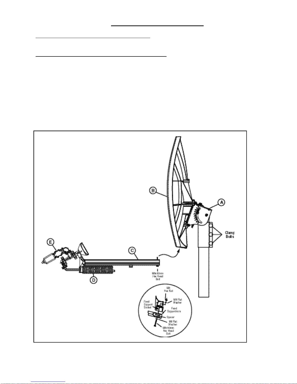
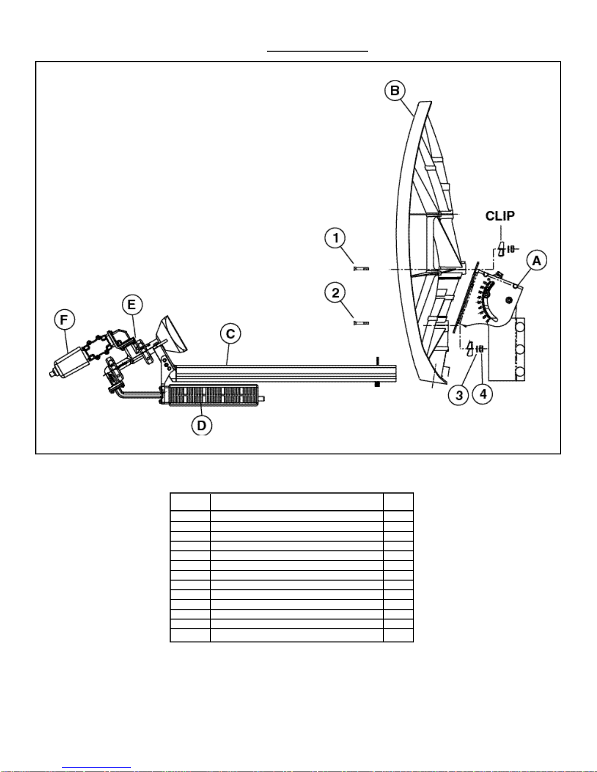
DESCRIPTION: The 75cm Elliptical Rx-Tx Antenna System is designed for two-way satellite communications, and
is suitable for commercial or consumer use.
CARTON CONTENTS: 75cm Elliptical Reflector and Roof/Wall Mount
AZ/EL Skew Mount Hardware Bag
Rx-Tx Feed Assembly w/Hardware Instruction Manual
CONTACT: StarBand Network Operation Center
Telephone: (888) 424-3993
TOOLS SUPPLIED: 10mm/13mm Open End Wrench
TOOLS REQUIRED: 1 - Compass 1 - Inclinometer
1 - 9” Magnetic Level 1 - Screwdriver (#2 Phillips)
SUGGESTED ADDITIONAL
TOOLS: 1 - 10mm Nut Driver 1 - Torque Wrench
1 - Ratchet Wrench (³⁄₈” Drive) 1 - 13mm Socket (³⁄₈” Drive)
1 - 10mm Socket (³⁄₈” Drive)
ADDITIONAL PRE-INSTALLATION MATERIALS
Grounding Rod, Clamp & Grounding Block - As required by National Electric Code or local codes.
Ground Wire - #10 solid copper or #8 aluminum as required by National Electric Code or local codes (length required).
RG-6 Coaxial Cables from antenna to indoor unit(s).
Installation Mount (as required by site survey)
SITE SELECTION
3

4
II. ANTENNA ASSEMBLY
2.1 Assembling the Reflector/AZ/EL Skew Cap Mount (Ref. Fig. 2.1)
Place the reflector/AZ/EL Skew Cap Mount assembly (A/B) onto mast pipe as shown in Figure 2.1.
2.2 Attach the Feed Support Arm Assembly to the Reflector (Ref. Fig. 2.1)
Remove the nut and flat washer from the M8 x 60mm hex head bolt from the feed support (C) and insert the feed
support into the socket on the bottom of the reflector (B). Secure the feed support with the flat washer and M8 hex
nut. While holding the M8 x 60mm bolt head with a wrench, tighten and torque hex nut to 6 Ft-lbs.
FIG. 2.1
A. AZ/EL Skew Mount Cap
B. 75 cm Elliptical Reflector
C. Feed Support Arm Assembly
D. Transmitter
E. Feed Assembly
Table of contents
Popular Satellite TV System manuals by other brands

Megasat
Megasat Multiswitch Series Installation instruction

Philips
Philips STU 904 Instructions for use

Dish TV
Dish TV DVB-S6800PLUS Operation manual

Avermedia
Avermedia AVer3D R889 quick guide

Kathrein
Kathrein MobiSet 2 Digital CAP 600 Installation and operating manual

KVH Industries
KVH Industries TracVision R5SL user guide