Standart ECO SNM Series Installation instructions

ECO SNM
Instruction for Operation
and Maintenance
Single Stage Norm Centrifugal Pumps

01.2017
Revision 0
Instructions for Installation, Operation and Maintenance
Standart Pompa ve Makina San. Tic. A.Ş.
All rights reserved. Can not be copied or reproduced for any purpose without permission.
Subject in the manual can be changed without any prior notice.

Contents
1. GENERAL
1.1 Safety Signs
1.2 General Instructions
1.3 Safety Instructions
1.3.1 CE signs and approvals
1.3.2 Explosive atmosphere
1.3.3 Labelling
1.3.4 Temperature classes and limits
1.3.5 Monitoring
1.3.6 Constructional requirements
1.3.7 Personel qualification and training
1.4 Recycling
2. GENERAL PUMP DESCRIPTION
2.1 Pump Description
2.2 Application Areas
2.3 Pump Designation
2.4 European Commission’s Regulation
2.5 Pump Nameplate
2.6 Technical Information
3. UNPACKING, HANDLING and STORAGE
3.1 Unpacking
3.2 Handling
3.2.1 General warnings
3.2.2 Lifting operation
3.3 Storage
4. INSTALLATION ON SITE
4.1 Bare Shaft Pump
4.2 Preparation for Installation
4.3 Installation Site
4.4 Installation Of The Piping System
4.4.1 General Warning
4.4.2 Suction pipe
4.4.3 Delivery pipe
4.4.4 Auxillary pipe connections and accessories
4.5 Minimum Flow
4.6 Electrical Connections
4.7 Final Controls
01
01
01
02
02
03
03
03
04
04
04
04
05
05
05
05
05
06
06
06
06
06
06
07
07
08
08
08
08
08
08
09
09
11
12
12
13

Contents
14
14
14
14
14
15
15
15
15
16
17
17
17
18
18
19
20
21
22
23
5. START UP / SHUT DOWN
5.1 Preparation
5.1.1 Venting and priming
5.1.2 Checking the direction of rotation
5.2 Start Up The Pump
5.3 Shut Down The Pump
5.4 Checks to be Made While The Pump is Running
6. DISASSEMBLY AND REASSEMBLY
6.1 Disassemblying the Pump
6.2 Tightening Torques
6.3 Assembling the Pump
6.3.1 Getting Prepared for Mounting
6.3.2 Mounting
6.4 Shaft Seal
6.4.1 Pump with mechanical seal
7. SPARE PART
8. FAULTS, CAUSES AND REMEDIES
9. EXPECTED NOISE VALUES
10. PUMP DIMENSION GROUPS
11. SECTIONAL DRAWINGS

01
General Risk
Signifies safety precautions which if not applied may cause vital.
Electrical Risk
Warnings about the electrical current
Warning
Safety instructions that if not applied may cause damage to the machine or operation.
This manual should be made available at a safety place easily accessible by personnel
responsible for safe operation and maintenance of the pump the qualified
1. GENERAL
The objective of this manual is to:
• Instruct the users on installation, dismounting, maintenance and repair of the pump, and
• Describe methods of start-up, operation and stop of the pump.
1.1 Safety Signs
1.2 General Instructions
• The authorized personnel should be experienced and well - informed about the related standards.
• The instructions given in this manual should be carefully read and applied at any phase of the
installation and operating process of the pump.
• The user is responsible to ensure that the inspection and installation are performed by the
authorized and qualified personnel, who read this manual thoroughly.
• The pump should never be operated beyond the operating conditions set forth in the purchase
order. The reason is that the operating conditions set forth in the purchase order have been taken
into consideration in the selection of the pump material and trial of the pump.
• If the pump is required to be operated apart from the conditions set forth in the purchase order,
please contact with STANDART POMPA. STANDART POMPA does not assume any responsibility
for any damages that may arise from operation of the pump beyond the specified conditions
without written consent.
• If the pump will not be installed at its place immediately after delivery, it should be stored at a
clean and dry place where the ambient temperature does not change excessively. If the proper pre
cautions are not taken, excessively low or high temperatures may cause serious damages to the
pump.
•
STANDART POMPA
does not accept any responsibility under warranty for any repair or
replacement performed by the user or any other unauthorized persons.
• This manual does not include safety rules applicable at the place of use.
Explosive atmosphere
Information to prevent explosion in the explosive atmosphere as per EC Directive
94/9/EC (ATEX)
ATTENTION

02
1.3 Safety Instructions
• Operate the pump only under the specified pump.
• Any tension, contraction and strain on the piping system should never transfer to the pump.
• Electric wiring of the engine and auxiliary components should definitely comply with the local rules
and be performed by the authorized personnel.
• Never perform any work on the pump before the pump set is stopped completely.
•
Any work on the pump should always be performed by at least two workers.
•
Clothing of the personnel to work on the pump should always be suitable for the works they will
perform and/or the personnel should use necessary safety equipment.
•
Never perform any work on the pump when it is hot.
•
Never touch the hot pump and pipes by naked hand. The user personnel should take necessary
warning precautions (e.g. warning signs, barricades, etc.).
•
Always be careful when working on the pumps delivering hazardous liquids (e.g. acid or hazardous
fluids).
•
When the pump and pipes connected to the pump are under pressure, do not perform any work on
the pump definitely.
•
Once the work on the pump is over, put in place all safety shields previously removed.
•
Never operate the pump in reverse direction.
•
Never insert pour hands and fingers into any hole or openings of the pump.
•
Do not trace on the pump and/or pipes connected to the pump.
1.3.1
CE signs and approvals
It is a legal requirement that machinery and equipment put into service within certain regions of the
world shall conform with the applicable CE Marking Directives covering Machinery and, where
applicable, Low Voltage Equipment, Electromagnetic Compatibility (EMC), Pressure Equipment
Directive (PED) and Equipment for Potentially Explosive Atmospheres (ATEX).
Where applicable, the Directives and any additional Approvals, cover important safety aspects
relating to machinery and equipment and the satisfactory provision of technical documents and
safety instructions. Where applicable this document incorporates information relevant to these
Directives and Approvals. To confirm the Approvals applying and if the product is CE marked, check
the serial number plate markings and the Certification, see the last page of this document.
Always observe the following instructions to prevent any physical and/or property
damages.
Always disconnect power connection with the engine before you perform any work on the
pump and make sure that no connection is made accidentally.

03
1.3.2 Explosive atmosphere
Detailed information about the operating conditions at the explosive atmospheres are found in
Directive on Equipment for Potentially Explosive Atmospheres 94/9/EC (ATEX 95).
The pumps to be used at the explosive atmospheres should never be used at areas apart from the
specified areas.
1.3.3 Labelling
Label on the pump is related with the pump only.
Motor:
It is required to be documented and labelled by the engine manufacturer.
1.3.4 Temperature classes and limits
During the pumping applications, the highest temperature occurs in the areas of the electric motor
bearing area, sealing area and volute casing. The volute casing temperature is almost same with
that of the fluid delivered by the pump. If the pump casing is heated externally, the technical
personnel should keep the temperatures under control according to the temperature classes.
Temperature classes given in the Table 1 and the highest permissible temperature for the pump
during operation are shown in the following table.
II 2 G/D c T4
1 2
3 4 5 6 7
1- CE logo
2- Ex logo
3- Group
4- Category
5- Explosive Atmosphere [Gas(G) and/or Dust(D)]
6- Protection Type (Constructional Safety as per EN 13463-5)
7- Temperature Class
Only the products certificated for the explosive atmospheres should be used
at the explosive atmospheres.
This section should be read carefully for the pumps operating at explosive
atmospheres.
Temperature
Class
T3
T4
Maximum Surface
Temperature
200 °C
135 °C
Maximum Permissible
Fluid Temperature
180 °C
110 °C
Temperature Limits
Table 1
Example II 2 G/D c T4
II 2 G/D : Group II, Category 2 Gas (G) and/or Dust (D) ambient.
c : Constructional Safety (c)
T4 : Temperature Class (T4)

04
1.3.5 Monitoring
The technical personnel should operate the pump within these limits and the status monitoring
system should be used for the pump set.
Use of the monitoring system is important especially for the following areas of the pump:
• Temperature values on the pump casing
• Temperature values in the sealing area
In the systems where buer liquid is supplied or double mechanical seal is available the buer liquid
should be observed.
• Temperature values in the electrical motor bearing area
For proper operation of the bearings, it would also be useful to monitor vibration and temperature
values in the roller bearing.
• The pump should be operated according to ordered duty point.
1.3.6 Constructional requirements
When explosive fluid is pumped, all parts under pressure should be made of ductile material.
Mechanical seals should never be operated dry. The sealing area should be filled with liquid
completely as long as the pump operates. If you are not sure that the sealing area is filled with
liquid, then the buer liquid may be applied.
Pump and/or pump set should always be earthed.
1.3.7 Personnel qualification and training
All personnel involved in the operation, installation, inspection and maintenance of the unit must
be qualified to carry out the work involved. If the personnel in question do not already possess the
necessary knowledge and skill, appropriate training and instruction must be provided. If required
the operator may commission the manufacturer / supplier to provide applicable training.
Always co-ordinate repair activity with operations and health and safety personnel, and follow all
plant safety requirements and applicable safety and health laws and regulations.
1.4 Recycling
For products and arts which will not be used and scraped, use the local or private waste collection
services. If it is not possible, consult the nearest authorized service centre of STANDART POMPA.
Pump and/or pumpset should be operated according to duty point and the limit
described in nameplate.

05
ECO SNM PUMPS
2- GENERAL PUMP DESCRIPTION
2.1- Pump Description
• ECO SNM series pumps are horizontal, radially split volute casing, single stage, end suction centrifugal pumps
with closed impeller.
• The dimensions of volute casing comply with EN 733.
2.2- Application Areas
ECO SNM series pumps are suitable for clean or slightly contaminated (max. 20 mg/dm3) liquids with low viscosities
and temperatures up to 140 º C . The main application areas, among others, are:
• Water supply, water treatment and irrigation systems,
• Heating, chilled and cooling water systems,
• Water systems for industrial uses,
• Industrial circulating systems,
• Fire fighting,
• Power plants.
2.3- Pump Designation
2.4- Product information according to European Commission's Regulation EU 547/2012
Relevant Pump Series
Water pump, end suction own bearing (ESOB) -ECO SNT
Water pump, end suction close coupled (ESCC) - ECO SNM
Water pump, end suction close coupled inline (ESCCi) - ECO SNL
Minimum efficiency index: MEI>=0,4
The benchmark for most efficient water pumps is MEI>= 0,7
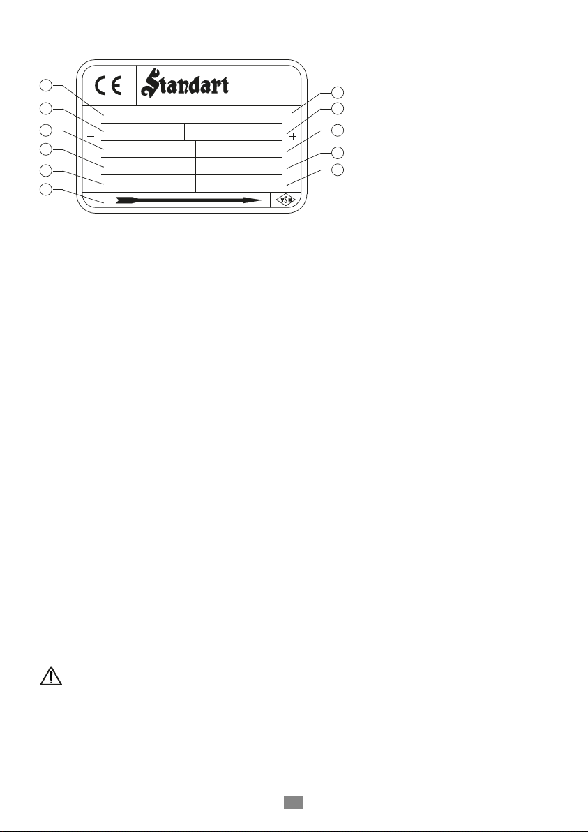
Year of production: Please see the pump label.
Manufacturer’s name or trademark: Standart Pompa ve Makina San. Tic. A.Ş.
Place of production: Turkey
Product’s type and size indicator: Please see the pump label and data sheets.
Pump performance curves, including efficiency characteristics: see documented characteristic curve
The efficiency of a pump with a trimmed impeller is usually lower than that of a pump with full
impeller diameter. Trimming of the impeller will adapt the pump to a fixed duty point, leading to
reduced energy consumption. The minimum efficiency index (MEI) is based on the full impeller
diameter.
Operation of this water pump with variable duty points may be more efficient and economic when
controlled, for example, by the use of a variable speed drive that matches the pump duty to the
system.
Information relevant for disassembly, recycling or disposal at end of life: see installation/operating
manual section 1.4
Information on benchmark efficiency graph is available at www.europump.org/efficiencycharts
Pump Type
Vertical Installation
Discharge Nozzle (DN-mm)
Nominal Impeller Diameter (mm)
Impeller Type
ECO SNM-V 100 - 250 ....

06
3- UNPACKING, HANDLING and STORAGE
3.1- Unpacking
• Check whether the package has been damaged during transportation.
• Remove unpackaged pump and accessories (if any) carefully. Check whether they have been damaged
during transportation.
• If any damage has occurred during transportation, notify SERVICE DEPARTMENT, STANDART
POMPA and SHIPPING COMPANY about it immediately.
• Check whether all materials in the shipping list have been delivered. If there is any missing article,
advise SERVICE DEPARTMENT, STANDART POMPA.
• Remove the liquid inside the pump, for preventing corrosion due to transportation.
3.2- Handling
3.2.1- General warnings
• Follow the rules at work to prevent occurrence of any accidents.
• Wear gloves, steel-tooled shoes and helmet during handling.
• You may use forklift, crane or hoisting ropes to lower wooden crates, packages, pallets
or boxes depending on volume, weight and construction of them.
2.5 Pump Name Plate
TP :
Y:
Q : m³/h
P : kW D : mm
n : η
opt
:
rpm
MEI ≥ 0,40
H : m
No :
1
2
4
6
8
3
5
7
10
9
11
İDOS 2. Cad. No.9
Ümraniye/İstanbul
Türkiye - 34776
+90 216 466 89 00
2.6- Technical Information
Discharge Nozzle : DN 32 … DN 150 mm
Operation Temperature : -10 ºC up to 140ºC
Casing Pressure (max) : 10 bar (16 bar)*
Permissible Liquids : See Section 2.2
The service life of this product as determined and announced by the Ministry is 10 years.
(*) Note: Contact our company for more detail.
1- Pump Type and Size
2- Production Year
3- Serial No
4- Capacity
5- Head
6- Motor Power
7- Impeller Diameter
8- Speed
9- Direction of Rotation
10- Minimum efficiency index
11- Efficiency

07
Figure 1a. Bare shaft pump Figure 1b. Pump and motor on a common baseplate
3.2.2- Lifting operation
- Total weight and centre of gravity,
- The largest outer dimensions, and
- Location of the lifting points.
• The load lifting capacity should comply with the weight of the pump or pump group.
• The pump or pump group should always be lifted and handled horizontally.
• Never stand under or near the load being lifted.
• Do not keep the load lifted longer than necessary.
• Accelerating and braking operations during the hoisting should not be performed in such a way that
may be dangerous for the working personnel.
The pump or pump group should be hoisted as shown in the Figure 1a or Figure 1b in order to avoid
from any deformation. (When the group is hoisted as a whole, never use the suspension hook of the
electric motor.
3.3- Storage
• If the pump will not be installed in place immediately, it should be stored at a clean and dry place
free of any frost hazard without excessive change in the ambient temperature.
• If the electric motor bearings are of grease-applied ones, extra grease should be applied to the
bearings to prevent moisture ingress around the shaft.
• Necessary precautions should be taken to protect the pump against humidity, dust, dirt and foreign
materials.
• The pump should be rotated manually by some turns occasionally (e.g. once in a week) to prevent
pitting on the bearing surfaces and sticking of the pump.
ATTENTION
• Determine the following points prior to lifting and handling the pump.
<90
<90

08
4- INSTALLATION ON SITE
Installation of the pump on site and levelling and adjustments of it should be performed only by
qualified personnel. Improper installation may cause failure. Such situations are excluded from
warranty.
Installation on site should be performed as per EN 60204-1 standard.
4.1- Bare Shaft Pump
• If the pump is supplied without motor, proper motor should be selected before the group is installed.
• Following points should be taken into consideration when selecting motor:
- Maximum power drawn by the pump along the entire operating range,
- Running speed of the pump,
- Applicable power supply (frequence, voltage, etc.),
- Motor type (TEFC, Exproof, etc.),
- Motor connection form (pedestal, flanged, horizontal, vertical, etc.), and
4.2- Preparation for Installation
Prior to installation of the pump in place:
• Suction and delivery flanges should be cleaned thoroughly.
• Never use the pump as a point of support or bearer for the piping system.
4.4- Installation of the Piping System
4.4.1- General Warning
ATTENTION
• The pump should be installed at a well-ventilated place free of freezing and explosion risk.
• There should be sucient space around the pump being installed to allow easy access for
maintenance of the pump as well as sucient space above the pump to hoist it when required.
• Suction pipe of the pump should be short as far as possible.
• The piping system should be supported at points near to the pump. For this purpose, after completion
of the installation of the piping system, loosen the bolts of the suction and delivery flanges and
control whether the piping system applies any tension on the pump.
• Rated diameter of the suction and delivery flanges of the pump are not indicator of the correct
sizes of the suction and delivery pipes at all. The rated diameter of the pipes and accessories used
should be equal to or larger than the inlet diameters of the pump at least. Never use pipes and
accessories having smaller diameter than the inlet diameters of the pump. Especıally components
such as bottom valve, strainer, dirt-retaining filter and check valves with larger free passage area
should be preferred. In general, flow rates should not exceed 2m/s for the suction pipe and 3m/s for
the delivery pipe. High speeds cause high pressure reduction and it, in turn, cause cavitation conditions
on the suction pipe and loss arising from excessive friction on the delivery pipes.
4.3- Installation Site
ATTENTION
ATTENTION

09
• Pipe connections should be made with the flanges. Flange bolts should be made of proper material
and in proper size. The flange bolts should be inserted between the flange bolts and centred in such
way that it would not impair flow section.
• In case of excessive vibrations and systems operating with hot liquids, expansion parts should be
used in order that any extra forces that may arise from thermal expansion are not transferred to the
pump.
• Materials such as welding burrs, metal particles, sand and oakum arising from production of fhe
piping system may remain in the pump and give damage to the pump. The suction and delivery
flanges should be sealed blind washers in order to prevent such materials from entering into the
pump during the assembly operations. After assembly, all pipe parts should be removed, cleaned,
painted and reassembled. If dirt-retainer is used on the suction side of the pump, the dirt-retainer
should be cleaned after working for several days.
4.4.2- Suction pipe
• The suction pipe should be definitely watertight and should not be arranged in a way to cause
formation of air pockets. In other words, if it is supplied from a reservoir higher than it (system with
elevated suction/supply), the suction pump should be slightly declined towards the pump; and if the
pump is supplied from a reservoir lower than it (system with suction depth), than the suction pipe
should be gradually inclined slightly towards the pump. Figure 2a and 2b
• In order to keep the loss from friction, sharp elbows should not be used; and abrupt change of
direction and section should be avoided and suction pipe should be made short as far as possible. If
it is required to make change of section on a horizontal suction pipe, an eccentric conical spacer with
its flat side on the top should be used.
4.4.3- Delivery pipe
•A flow control valve should be connected on the delivery pipe, near the pump as far as possible in
order to adjust the flow rate and delivery head.
• If the delivery head of the pump is more than 10 m or the delivery line is quite long, a check valve
should be connected between the pump and flow rate adjusting valve on the delivery pipe in order
to protect the pump against water hammers when stopping the pump or prevent backflow.
• If the pump is supplied from a reservoir higher than it, an insulation valve should be
used to keep the axis on the suction pipe horizontally. This valve should always be open
when the pump operates and it should never be used as flow rate adjusting valve
(Caution: Throttle of the valve may cause the pump to operate with cavitation).
ATTENTION

10
Figure 2a. Suction Lift
Eccentric
Rudecer
Compansator
Eccentric
Rudecer
Flow Control Valve
Non Return Valve
Foot Valve (full passage)
Strainer
Figure 2a. Suction Flooded
Isolation Valve
Compansator
Non Return Valve
Flow Control Valve

11
Isolation Valve
Vent Valve
Figure 3
4.4.4- Auxiliary pipe connections and accessories
• Depending on the application auxiliary pipe connections (for
cooling, sealing and flushing of seal, drainage etc. necessary for
the pumping system) and/or accessories to check operating
conditions (pressure gauges, temperature gauges etc.) may be
made up and lail.
• Pressure and vacuum gauges must be properly anchored and
connected at the measuring points located on the pump flanges
by means of or on the pipes close to the flanges approximately
8 mm diameter tubing with pig tail configuration to lessen
pressure fluctuation. For safety purposes isolating and vent valves
should be fitted before the gauges (Figure 3).
• Every pump is fitted with connections on the pump casing to
drain the pump (Figure 4). If required the pump drain can be piped
to a suitable reservoir. The pump draining piping must be fitted
with an isolating valve and both must be suitable for the
maximum operating pressure of the pump.
• Cooling, sealing and flushing of seal piping must be connected
only to the designated connections located on the pump
(Figure 5,6).
d1 : Pressure gauge (discharge)
d2 : Pressure gauge (suction)
d3 : Filling or vent
d4 : Drain
Figure 4
Figure 6Figure 5
d3
d1
d4
d2
F1 F1 Q1
Q2
F1 : Seal flushing liquid inlet from external source
Q1: Mechanical seal quench liquid inlet from external source.
Q2: Mechanical seal quench liquid outlet.

12
• The electrical motors have to be built in accordance with EN 60034-1.
• Enclosures of electrical motors and control systems on the pump unit shall as a minimum
have protection in accordance with EN 60529 IP22. But in determining the degree of protection
of enclosures of electrical motors and control systems on the pump unit the operating and
environmental conditions must be taken into consideration.
If there is possibility of the pump operating with its delivery valve is closed completely
(that is, at zero flow rate) or almost closed (that is, at very little rate), a by-pass valve
should be used on the outlet flange of the pump or on the delivery pipe just after the
pump, but in advance of the control valve should be used. If such a valve is not used and
the pump operates for a long time, almost all power given by the engine converts to
thermal energy and transfers to the delivered liquid. This situation may cause overheating
and, consequently, cause significant failures.
• Electirical connection should be done by a qualified electrician. Current national regulation and
motor manufacturer’s instructions must be observed.
• Take all safety precautions listed in “Safety instructions”. Disconnect all power supplies prior to
doing any work.
• The supply cable must be laid in such a way that it never touches the pipework, pump and motor
casing.
• Check voltage, phase and frequency on motor nameplate with the mains.
• The electric motor must be protected against overloading by means of circuit breakers and/or fuses.
Circuit breakers and fuses must be selected in accordance with full load amperage of the motor
appearing on the motor rating plate.
• It is recommended to use PTC (passive thermal control) on motor, bu this is optional depending on
customer requirement. In case of using PTC, these should be connected via corresponding terminals
in the terminal box and the PTC should be connected to the thermal trip mechanism.
• Prior to connection the electrical wiring rotate the pump shaft by hand to make sure rotor rotates
easily.
• Connect the electrical wiring in accordance with local electrical codes and make sure to ground the
motor.
• The connection diagram can be found in the terminal box of the motor or in the instruction manual.
• The mains connection on the terminal box depends on the nominal power of the motor, the power
supply and the type of connection. The necessary coneccton of the bridges in the terminal box is
shown in the following (Table 2 ve Figure 7a, 7b, 7c).
4.6- Electrical Connections
4.5- Minimum Flow
ATTENTION
ATTENTION

W
2
U
2
V
2
U
1
V
1
W
1
L
1
L
2
L
3
W
1
V
2
L
1
V
1
U
2
U
1
L
2
W
2
L
3
W
1
V
2
L
1
V
1
U
2
U
1
L
2
W
2
L
3
Figure 7a. ∆ - connection Figure 7b. Y – connection Figure 7c. Y / ∆ - connection
Type of switch
Motor Power
P
N
≤ 4 kW Motor Power
P
N
> 4 kW
Power Supply
3 ~ 400 V Power Supply
3 ~ 400 V
direct Y – connection (11b) ∆ – connection (11a)
Y / ∆ - start Impossible Remove connection
bridges (11c)
Table 2
Motor Power Y - set time
≤ 30 kW
> 30 kW < 3 second
> 5 second
Table 3
In the case of three-phase induction motors with Y - ∆connection it must be ensurred that
the change-over points between star and delta follow on from one another very quickly.
Longer change-over times may result in pump damage (Table 3).
13
4.7- Final Controls
• The pump rotor should be rotated several times manually to make sure it rotates easily.
• All security guards should be put in place.
• And the pump group should be operated and you should allow until the operating and heating
conditions are reached.
• The pump should never be operated before the safety guards are put in place. This is a
security and safety rule at workplace which should be definitely observed.

14
5- START UP / SHUT DOWN
5.1- Preparation
5.1.1- Venting and priming
• Make sure that the pump and suction pipes are completely filled up with water. There is no problem
for the pumps which have positive suction head. If there is a valve on suction line, it must be opened
and air taps are loosened to enable the water replaces air in the pump, until it is completely full with
water.
• If there is a foot valve on the suction line, the air should be emptied out.
• If the system has a vacuum pump, water is brought up in the rising pipe and filled up the pump
through this vacuum pump. When water is risen up to the highest point then the pump is started
up.
Make sure the pump never runs dry.
5.1.2- Checking the direction of rotation
• ECO SNM type pumps rotate in clockwise when it is looked from coupling to the pump. This direction
is already indicated on the pump nameplate by an arrow. Check this by switching the pump on, then
o again immediately. Fit the coupling guard back in place if you took it out.
5.2- Start Up The Pump
• Check if the shut o valve in the suction line is open and the shut o valve in discharge line is closed.
• Switch on the circuit breaker and run the motor.
• Wait until the motor reaches the full speed (on star-delta running motors wait until it switches on
delta).
• Open the discharge valve slowly while watching the ampermeter on the control panel (if the discharge
line is empty do not turn on the valve fully open on first start up. Turn it on slowly to maintain the
value on the ampermeter is under the rated current value of the motor).
• When the valve is if fully open, check the pressure on the manometer and see it is the same with
the duty point pressure. If the pressure on the pressure gauge is lower than duty point pressure brings
them to the duty point value by slightly closing the valve. If it is higher value, check your installation,
especially geometric height again.
The pump should be shut down at once and the trouble should be corrected if the pump
is running at its rated speed and found any of the following faults:
ATTENTION
ATTENTION
• Pump doesn’t deliver any water,
• Pump doesn’t deliver enough water,
• Flow is going down,
• Discharge pressure is not enough,
• Driver overloaded,
• Vibration on pump,
• High noise level,

15
5.3- Shut Down The Pump
• Slowly close the shut-o valve in the discharge line.
• You may shut down pump without closing the shut-o valve if there is a device for water hammer
protection on the discharge line or the water hammer is not a considerable level.
• Switch o the drive. Ensure the pump set runs down smoothly and quietly to a standstill.
• Shut o external sealing liquid supply, if supplied to relieve stung box pressure.
• If the set is to remain out of services for a long time close the shut-o valve in the suction pipe.
Close o the auxiliary connections. In the event of frost and/or prolonged standstill, drain the pump
or otherwise protect against freezing.
5.4- Checks to be Made While The Pump is Running
• The valves in the auxiliary lines must remain open while the pump is runing.
• If the pump has a mechanical seal, experience only minor leakage or no visible leakage during
operation. It is maintenance free. If there is considerable leakage from the seal, that means the seal
surfaces are worn-out and it needs to be replaced. The operation life of the mechanical seal highly
depends on the purity of the liquid.
• Occasionally check the motor current. Stop motor if the amperage is higher than usual; there may
be jamming or friction in the pump. Make the necessary mechanical and electrical checks.
• Stand-By pumps should be run for a short time at least once a week to ensure they are in constant
readiness for operation. Check the integrity of auxiliary connections.
• The pump must never run dry.
• Never run the pump for along period against a closed discharge valve (at zero flow)
Before working on the pump, always disconnect the electrical connections and ensure
that you take all the necessary actions to prevent undesired operation.
Strictly follow the instructions given in “Safety Instructions” section.
6- DISASSEMBLY AND REASSEMBLY
6.1- Disassemblying the Pump
• Shut o the isolation valves on the suction and delivery line. Open the blind plug (230) and drain
the water inside the pump.
• Disconnect the pump from the piping system by removing the suction and delivery flanges of the
pump and auxiliary pipe connections.
• Dismantle the safety guards. (550)
• Dismantle stud, washer and nut (301) from the volute casing (001). So the volute casing (001) might
be removed easily.
• Dismantle the impeller nut and washer (065).
ATTENTION

16
• Remove the impeller (050) with lever or screwdriver and etc.
• Remove the impeller key (210). Use rust remover solvent, if necessary.
• Remove the O-ring (420).
• Take the mechanical seal spacer sleeve (049) or shaft sleeve (070).
• Remove the mechanical seal (405).
• Remove the mechanical seal cover(043).
• Refer to (Section 6.4.1) for mechanical seal.
• Remove the shaft (060) by untightening the set screws (380)
• If rigid coupling is used, remove the shaft by untightening screws (320) from rigid coupling (085)
• Remove the allien screw and washer (340). It is easy remove rigid coupling (085) from electric motor
(600).
•Remove the motor pedestal (005) from electric motor.
The following tightening torques must be taken into consideration when tightening
the bolts and nuts during installation.
6.2- Tightening Torques
Table 4
ATTENTION
The sharp areas on the impeller edges can injure. Use protective gloves.
ATTENTION
The O-rings used after dismantling the pump must always be replaced.
ATTENTION
Be careful when removing the mechanical seal. Any potential impact on the stationary
element of the mechanical seal may cause the breakdown of the mechanical seal.
ATTENTION
Figure 8. Disassembly of impeller
Table 4 (continue)
Tightening
Torques (Nm)
Tightening
Torques (Nm)
Thread
Diameter
7
20
40
65
100
M6
M8
M10
M12
M14
M16
M18
M20
M22
M24
Thread
Diameter
130
140
140
140
200
This manual suits for next models
38
Table of contents
Other Standart Water Pump manuals
Popular Water Pump manuals by other brands

FILL-RITE
FILL-RITE FR150 Installation and operation manual

Oase
Oase Aquarius Universal Premium Eco 4000 operating instructions

Grundfos
Grundfos ALPHA Installation and operating instructions

Ingersoll-Rand
Ingersoll-Rand PM20X-X-X-B02 Operator's manual

Armstrong
Armstrong VMS Series Installation and operating instructions

SPERONI
SPERONI CAM 198 operating instructions