Standen Unistar 2400 Service manual

Unistar 2400
Soil Separator
Standen Engineering Limited.
Hereward Works,
Station Road, Ely,
Cambridgeshire.
CB7 4BP
England.
Tel: 01353 661111 www.standen.co.uk Fax: 01353 662370


On delivery check that the machine is as ordered and has not been damaged in
transit. Please report any shortfall to your Standen dealer.
The contents of this handbook, although correct at the time of publication, may be
subject to alteration by the manufacturers without prior notice.
Standen Engineering Limited operates a policy of continual product development.
Therefore, some illustrations and/or text within this publication may differ from your
machine.
The copyright of this handbook is the property of Standen Engineering Limited,
Hereward Works, Station Road, Ely, Cambridgeshire. CB7 4BP. This handbook is
issued on the condition that it must not be used, copied or exhibited without their
written permission.
IMPORTANT
This operator’s handbook should be regarded as part of the
machine. Suppliers of both new and second-hand machines are
advised to retain documentary evidence that this handbook was
supplied along with the machine.
On installation of the machine (i.e. starting off in the field), the New
Machine Installation Record Card should be completed by the
dealer/distributor and be countersigned by the customer. The
document is proof that the correct procedures have been followed.
The New Machine Installation Record Card should be returned to
Standen Engineering Limited within 7 days of installation. Failure to
do so may invalidate the machine warranty.


INTRODUCTION
Introduction to the Handbook 1.1
Warranty 1.1
Replacement Parts 1.2
SAFETY PRECAUTIONS
Safety 1.3
HSE Information Sheet 1.5
INSTALLATION
Tractor Suitability 1.7
Tractor Wheel Settings 1.7
Drawbar 1.7
Hydraulically Damped Drawbar 1.8
PTO Shaft 1.9
Hydraulic Connection 1.10
Open/Closed Centre Hydraulics 1.10
OPERATION
Electrical Control System 1.11
Wheel Settings 1.13
Automatic Depth Control 1.14
Setting the Automatic Depth Control 1.14
Discs 1.16
Shares 1.16
Underweb 1.16
Boulder Box 1.17
Cross Conveyor 1.17
Braked Axles 1.18
Actiflow Star Spacing 1.18
Vari-Flow Web 1.18
MAINTENANCE
Lubrication 1.19
Drive Belt Maintenance 1.20
Electrical System Maintenance 1.20
Hydraulic System Maintenance 1.20
Residual Hydraulic Pressure Dump Procedure 1.21
Star Shaft Removal 1.21
Daily Maintenance 1.22
Weekly Maintenance 1.22
Annual Maintenance 1.22
Out of Season Storage 1.23
SPECIFICATIONS
Machine Dimensions 1.24
Machine Weight 1.24
Technical Data 1.24
CONTENTS

Introduction to the Handbook
This handbook provides the information for the operation, adjustment and
maintenance of your Standen Unistar 2400 Soil Separator. To enable you to achieve
the best results from the machine, the manufacturer recommends that you read the
handbook thoroughly prior to using the machine for the first time.
Record below the details of your machine.
Dealers name...............................................................................…………….
Address......................................................................................................
.................................................................................................................
Telephone number.................................................................................…….
Machine serial number...............................................................................…
Date purchased............................................................................................
Date started work........................................................................................
This symbol indicates important safety messages within this handbook.
When you see this symbol, be alert to the possibility of injury to yourself
or others and/or damage to the machine and carefully read the message
that follows.
Throughout this handbook the terms 'front', 'rear', 'left-hand' (LH) and 'right-hand'
(RH) are derived from the tractor driver’s position facing forward in the normal
direction of travel.
Adjustments to the machine may have to be made singly or in combination according
soil conditions. Always allow the machine to settle to a new setting before making
further adjustments.
Recommended lubrication and maintenance instructions are included in this
handbook and if followed will help to keep the machine in a safe working condition.
Warranty
Should the machine suffer any faults or defects within the warranty period, please
contact your dealer. The warranty shall be effective only if the dealer is informed of
any such defect as soon as practicable upon discovery.
1.1
INTRODUCTION

Replacement Parts
Recommended replacement parts are designed for your machine and have the full
backing of the warranty. Only when recommended parts are used can responsibility
be considered under the terms of the warranty.
The rear of this handbook contains lists of spare parts available through your
Standen Agents. Each illustration shows a complete unit or assembly in exploded
form. Standen's policy of continual product development means that components or
even complete assemblies are redesigned from time to time. Where possible the
modifications are shown in the remarks column.
The first printing of each page in the spare parts section is identified as issue 1 at the
foot of the page. When a complete unit or assembly has been redesigned the
appropriate pages are revised and printed as issue 2. The revised pages are filed
behind the existing issue so that a complete modification history is gradually built up.
When using an illustration and parts list it is essential that both are of the same issue.
Always quote the full serial number of your machine when ordering spare
parts.
INTRODUCTION
1.2

Safety
The Standen Unistar 2400 has been designed to comply with current Safety
Regulations. However, as with all machinery there will be inherent dangers whilst
operating and carrying out maintenance on the machine. The following list of
precautions should therefore be brought to the attention of all persons operating and
working on the machine. The list is not exhaustive. All machinery is potentially
dangerous and great care must be exercised by the operators at all times. Standen
Engineering Limited will not accept liability for damage or injury caused by their
products except when such liability is specifically imposed by English statute.
The machine must never be operated by untrained personnel or
children.
Always check that the machine has been correctly mounted to the
tractor before setting off on operations and the stabilizers are correctly
set.
Never set machinery in motion before ensuring that everyone in the
vicinity is aware of your intentions.
Never allow children or animals in the vicinity where machines are
working and never allow anyone to ride on the machine.
In dry, dusty conditions it is prudent to use a tractor with an enclosed
cab.
Never attempt to fit drive chains or drive belts to the machine while the
drive sprockets or pulleys are in motion.
Normal safe working procedures should be adopted at all times.
Reduce speed when transporting the machine on sloping ground.
Do not work on ground where there is a possibility of overturning or
across steep slopes.
The working area should be kept clear and free of obstructions at all
times. Be alert for hidden obstructions. Should the machine hit an
obstruction, stop and check for damage before proceeding.
Wear substantial or proper safety footwear. Avoid loose clothing near
moving parts. Wear gloves when handling the implement or parts with
sharp edges.
Before carrying out any work on the machine, lower the machine to the
ground, switch off the tractor engine, apply the handbrake, remove the
ignition key and disconnect the PTO shaft.
1.3
SAFETY PRECAUTIONS

The operator must not leave the tractor seat until the machine has been
lowered to the ground, the tractor engine switched off, the handbrake
applied and the ignition key removed.
Never reverse or turn unless the machine is in the raised position.
All guards, covers, warning transfers and safety devices must be
correctly fitted and operable at all times.
Inspect the machine on a regular basis and replace damaged or worn
parts as necessary.
Inspect the machine for damage after use. Rectify as required.
Never operate the machine in a state of disrepair.
Only transport the machine at a speed suitable to the prevailing
conditions. Be aware of the weight and overall length of the machine at
all times.
Before working on the machine, all free moving parts should be locked
to prevent them moving.
Regularly lubricate the machine as per the operator’s handbook and
check the tightness of all nuts and bolts, particularly those securing the
rotor blades/tines.
Always use mechanical or additional help when lifting heavy parts.
Regularly check hydraulic hoses for chafing or damage and replace as
necessary.
Care must be taken when carrying out any work on the hydraulic
system. Even when stopped and disconnected from the tractor, residual
pressure will exist within the hydraulic system. Therefore, before
commencing any work on the hydraulics ensure that the system is free
of residual pressure by carrying out the ‘pressure dump’ procedure
outlined within this handbook.
Before transporting the machine on a public road, set the hydraulic
levelling to its lowest position, fully raise the shares, lock the cross
conveyor into the transport position, set the drawbar and steering to the
straight-ahead position and switch off the control box to avoid
inadvertently operating any machine services. Finally, ensure road
lights are clean and in good working order.
Safety is the responsibility of the persons working with this
machine. Think "safety" at all times. Read and remember the
contents of this handbook.
SAFETY PRECAUTIONS
1.4

1.5
SAFETY PRECAUTIONS

SAFETY PRECAUTIONS
1.6
Tractor Suitability
The power requirement for the Unistar 2400 is 200 bhp minimum.
The tractor must be of a suitable size to lift the implement safely. This
may entail the fitting of front weights to counterbalance the machine
when in the raised position.
Tractor Wheel Settings
Both front and rear tractor wheels must be set to run down the centre of the
wheelings and must span the bed being lifted. Consult your tractor handbook for the
correct procedure for setting the tractor wheels.
When carrying out wheel adjustments, always place the jack on firm
ground under a solid part of the tractor. Before removing a wheel,
place a stout support under the tractor frame in case the jack should
become dislodged.
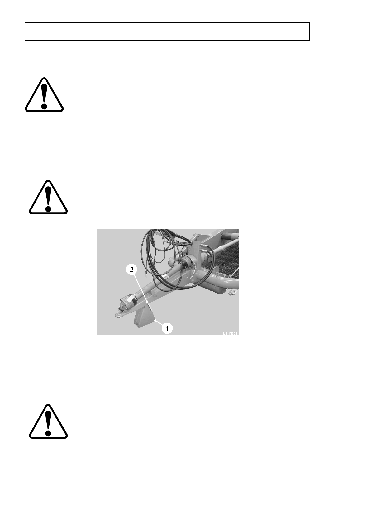
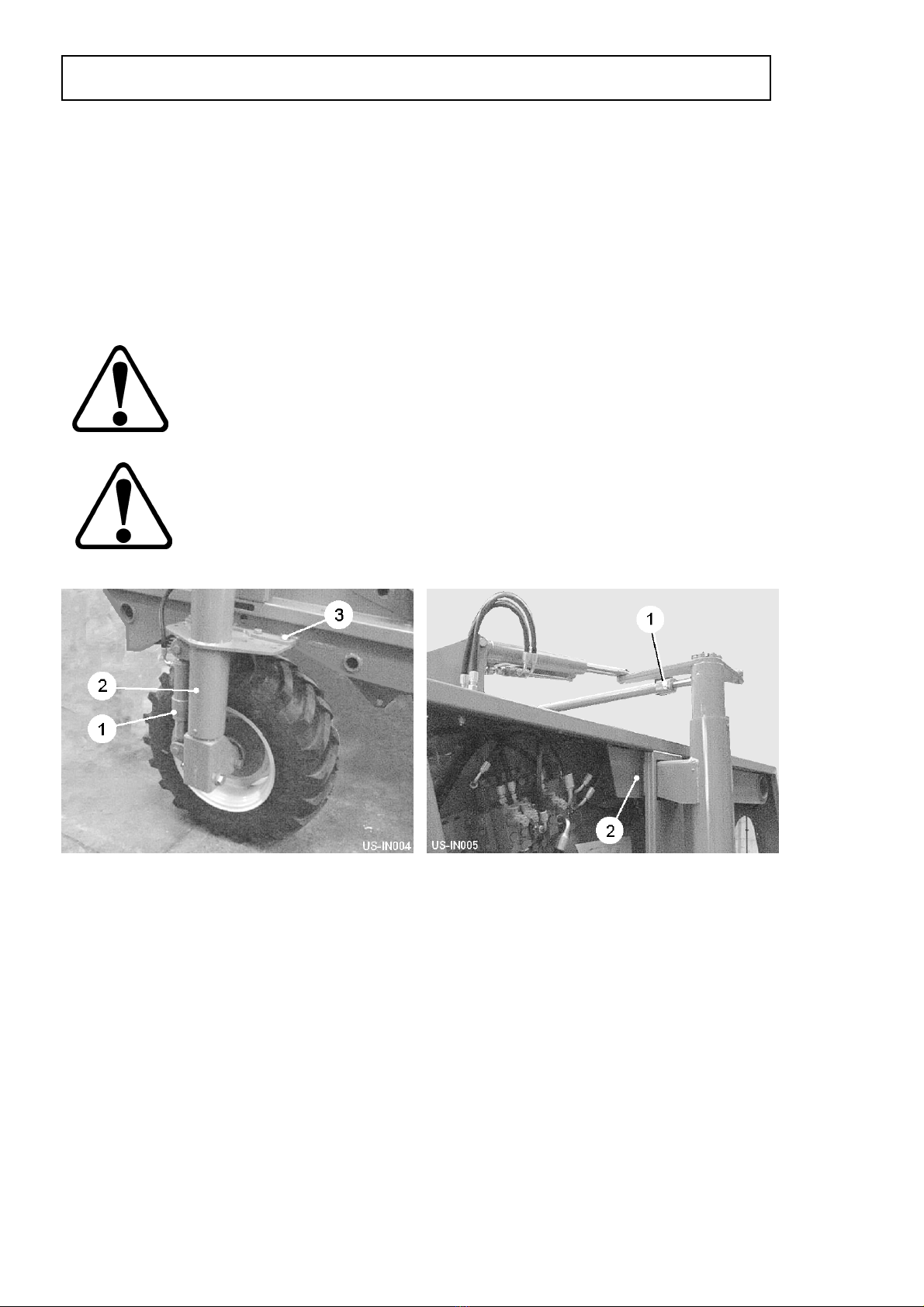
Drawbar
The drawbar is designed to be attached to the tractor pick-up hitch.
The jack stand (item 1, fig 1) is provided so that the machine is held at a suitable
height for safe coupling to the tractor.
Always ensure the stand is positioned on firm, level ground to avoid the
machine sinking or sliding whilst stood. Both wheels should be
chocked front and rear before removing from tractor.
Do not store the stand separately from the machine. You never know
when it will be needed.
When the machine has been securely attached to the tractor, the jack stand can be
folded back into the stored position by removing the anchor pin (item 2, fig 1),
rotating the stand and then securing it with the anchor pin.
1.7
INSTALLATION
Fig 1

Hydraulically Damped Drawbar (optional)
The hydraulically damped drawbar is fitted to protect the machine when operating in
soil conditions where buried obstructions may be encountered. The system consists
of a hydraulic cylinder mounted within the drawbar pressurised by an accumulator
(item 1, fig 2). The design allows the drawbar to extend by 200mm. After 25mm of
movement a proximity sensor triggers the control system which simultaneously lifts
the digger on full flow, and stops the boulder box stars, vari-flow and cross conveyor
webs. After activation the machine elements have to be restarted using the control
box. The drawbar must always be pressurised before commencing work.
To set the accumulator pressure, connect the hose (item 2, fig 2) to the tractor spool
valve and open the accumulator valve (item 3, fig 2). Open the tractor spool valve
while closely watching the pressure gauge (item 4, fig 2). When the pressure reaches
65 bar immediately close the spool valve and then close the accumulator valve. If
necessary, reduce the pressure slightly using the accumulator valve. The drawbar is
now pressurised and ready for operation. If in work, due to differing soil conditions,
the initial setting of 65 bar is found to be too low and the drawbar is extending in
normal work, increase the pressure setting by increments of 10 bar until the drawbar
is static. DO NOT EXCEED 120 BAR. If the drawbar is still not functioning correctly
when the maximum pressure is reached, consult your Standen dealer for further
advice.
Do not carry out maintenance on the drawbar with circuit pressurised.
Stop the tractor engine and reconnect the hose to the tractor spool
valve. Open the accumulator throttle valve and operate the spool valve
to dump the hydraulic pressure within the system.
INSTALLATION
1.8
Fig 2
minimum1/2 overlap
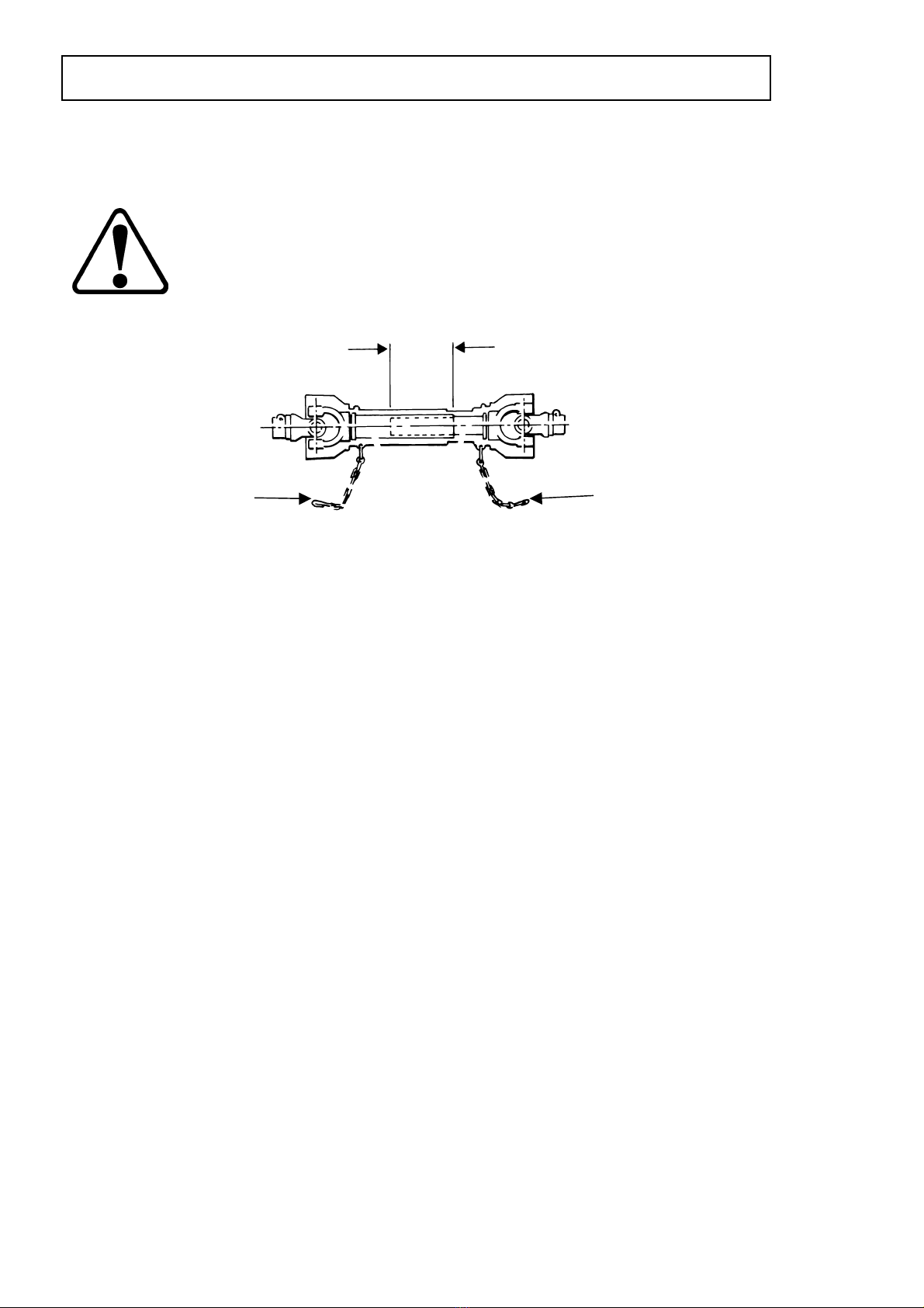
PTO Shaft
The machine is designed to operate with the tractors 540 rpm, 6 spline, 1 3/8” PTO
output shaft.
PTO speeds greater than 540 rpm will cause damage to the system
and if exceeded may invalidate the warranty.
Fit the two halves of the PTO shaft onto their respective drive shafts on the machine
and tractor. Check the shaft length by turning the tractor fully in both directions with
the machine in its working position while attached to the tractor’s pick-up hitch.
Ensure the sliding tubes, when fully extended, have an overlap at least half the
closed length (see figure 3). Ensure that the ends of the sliding tubes when at the
shortest point are not in contact with other parts of the PTO shaft. If necessary,
shorten both tubes and guards equally to achieve end clearance at the minimum
length position.
Make sure that the drive shaft is fitted correctly and that the lock pins are engaged.
All the parts of the PTO shaft, especially the guards, must be kept in good order.
Check regularly that the guard is undamaged and fully protects the whole of the
shaft, and that both the guard and the shaft will telescope freely.
If it is possible to engage the inner and outer parts of a drive in more than two
positions circumferentially then make sure that the universal joint yokes are correctly
aligned.
Check that when in the continuous working position, the drive shaft is not at an angle
of more than 20° from the PTO centre line. The angle between the drive shaft and
the input and output shafts should be equal.
Ensure that the safety chains (item 1, fig 3) used to prevent the guards from turning,
are fixed to the tractor and implement in such a way that they will not be stretched
when the drive shaft is at maximum articulation. When disconnected from the tractor,
position the PTO shaft on the drawbar PTO rest as shown in figure 1.
1.9
INSTALLATION
1
1
Fig 3
Hydraulic Connection
The feed and return hoses from the machine must be connected to the respective
external service connections of the tractor hydraulic system. Both feed and return
hoses have labels with arrows indicating the direction of oil flow.
The tractor hydraulic system must be set to constant pumping. Consult the tractor
manufacturers handbook for details about connecting external equipment to the
hydraulic system and hydraulic pump settings.
Required oil flow from tractor system minimum 70 ltr/min
(Set to constant pump) maximum 100 ltr/min
(For flows greater than 100 ltr/min consult your officially appointed Standen dealer)
There must no restriction in this return oil. Ensure that there is a full flow return, or
even better return straight back into the tractor gearbox. Consult your tractor
handbook or dealer for further information.
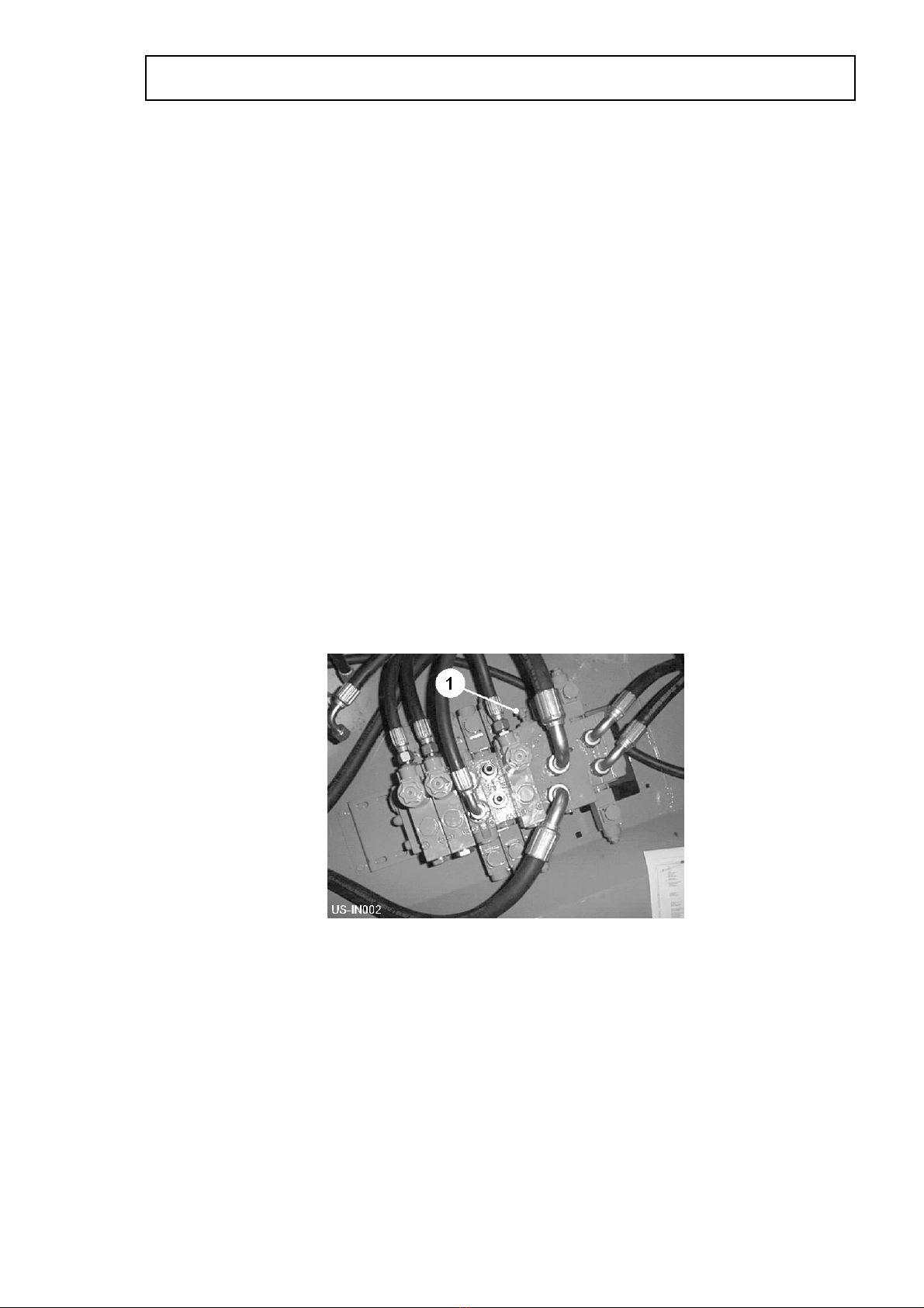
Open/Closed Centre Hydraulics
Two types of hydraulic system are currently in use by tractor manufacturers, namely
OPEN CENTRE or CLOSED CENTRE configurations. Consult the tractor
manufacturers handbook or dealer for further information.
The main hydraulic valve bank, situated behind the rear LH guard of the machine,
incorporates an adjustable screw (item 1, fig 4) which enables easy changing from
closed to open centre and vice versa. For closed centre configuration tractors, turn
the screw clockwise until fully closed. For open centre, turn the screw anticlockwise
until fully out.
INSTALLATION
1.10
Fig 4
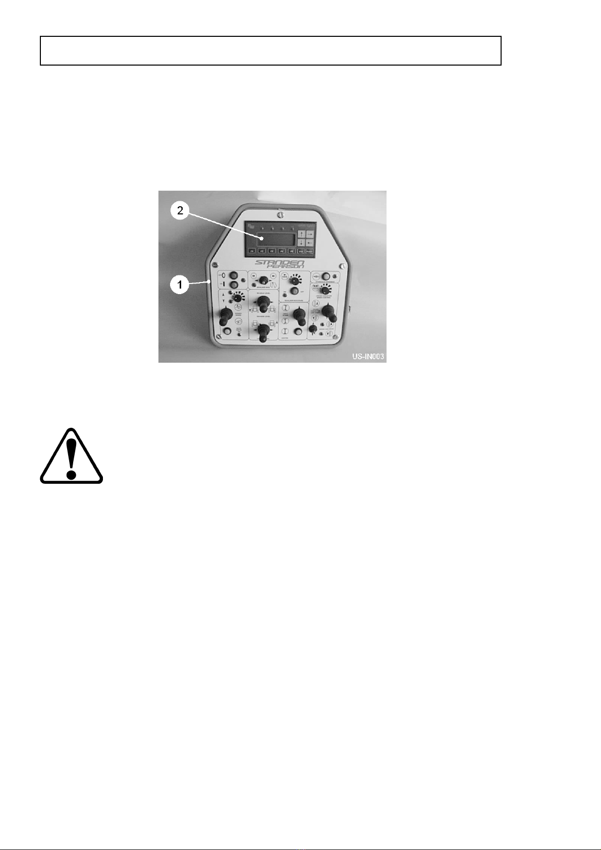
Electrical Control System
Control for the major functions of the Standen Unistar 2400 are provided
electronically by the switches mounted on the in-cab control box (item 1, fig 5)
switching the valves on the machine via a CAN-Bus control system. The functions
can be monitored from the control box display screen (item 2, fig 5). Setting and
monitoring can be carried out by following the instructions in the CAN-Bus operating
instructions.
Ensure that all plug and socket connections are clean and coupling pins undamaged
before connection, and that they are securely locked together before the power is
switched on. The function of each control box switch is explained below.
Do not leave or store the control box outside in the open and always
disconnect the control box from the tractor electrical supply when not in
use, so avoiding the possibility of draining the battery.
Hydraulic Drawbar (optional)
The hydraulic drawbar push button activates/deactivates the hydraulically damped
drawbar system. The LED is illuminated when the system is switched on.
Digger Share Raise/Lower
The 3 position spring toggle switch manually raises/lowers the digger assembly
increasing/decreasing the depth of the shares below the soil. Releasing the switch to
the central position leaves the share depth at the present setting. Setting the switch
to the locked lower position enables the depth rams to free float.
Auto-Depth
With the digger share switch set in the lower position, the push button
activates/deactivates the digger share auto-depth system. The share depth is
automatically adjusted by the movement of the diablo roller. The LED is illuminated
when the system is switched on. Operating the manual digger share raise/lower
switch will override the auto-depth system. The auto-depth indicator lights show
when the depth control sensors are operating. In work the digging depth can be
varied using the digger share dial. Turn the dial clockwise to increase the share
depth and anticlockwise to decrease the depth.
1.11
OPERATION
Fig 5

Axle Steer
The axle steer switch manually steers the machine wheels to left/right.
The auto-centre button when pressed operates the self-centring circuit to
automatically set the wheels to the straight-ahead position.
Axle Level
The two axle level switches operate the LH and RH levelling rams (item 1, fig 6).
Moving the switch to left will lower the LH side machine. Moving the switch to the
right will raise the machine.
Cross Conveyor Side Shift
The 3 position spring toggle switch operates the side shift ram which moves the
cross conveyor to discharge to LH or RH position.
Cross Conveyor Drive
The switch marked ‘cross conveyor drive’ starts/stops the cross conveyor web to
discharge to the LH or RH side of the machine. With the switch in the centre position
the discharge web is stopped. Move the switch up to discharge to the RH side of the
machine, or down to discharge to the LH side. The corresponding LED will illuminate.
The dial marked ‘cross conveyor speed control’ sets the speed of the discharge web.
Turn the dial clockwise to increase or anticlockwise to decrease the speed.
Boulder Box Stars (optional)
The push button starts/stops the boulder box stars. The LED is illuminated when the
unit is running. The dial increases/decreases the speed of the stars. Turning the dial
clockwise will increase the speed, while turning the dial anticlockwise will reduce the
speed. The switch opens/closes the boulder box for emptying. To empty the boulder
box move the switch to the right. The LED will illuminate when the box is open.
OPERATION
1.12
Wheel Settings
The machine wheels must be set for work in a specific bed width. The wheels should
be set to match the tractor wheels.
Each wheel is carried by a wheel leg pillar (item 2, fig 6) The pillars have a top and
bottom flange plate containing a series of fixing holes. Moving the pillars in or out
adjusts the wheel centres to suit the selected bed width. Both wheel legs must be set
to the same hole positions so that the wheels remain symmetrical about the
centreline of the machine. Lifting equipment must be used when setting the wheels.
Before commencing axle adjustment, ensure adequate jacks, axle
stands of minimum 2500 kg capacity, wheel chocks and suitable lifting
equipment are available.
It is important that the machine is correctly fitted to the tractor and that
the tractor handbrake is applied whilst axle adjustments are made.
Place chocks at the front and rear of the opposite side wheel to the one being
adjusted. Jack up the machine and place an axle stands under the chassis and lower
the jack to allow the axle stands to take the weight of the machine.
Release the track rod locking bolt (item 1, fig 7) and remove the flange plate
mounting bolts (item 3, fig 6 & item 2, fig 7). Using lifting equipment, carefully slide
the leg pillar to the required position. Refit the mounting bolts (item 3, fig 6 & item 2,
fig 7) through the relevant hole in the flange plates. Repeat the procedure for the
opposite wheel. Finally, set the track rod to the correct length and secure using the
locking bolt. Ensure all nuts and bolts are fully tightened after adjustments have been
completed.
1.13
OPERATION
Fig 6 Fig 7
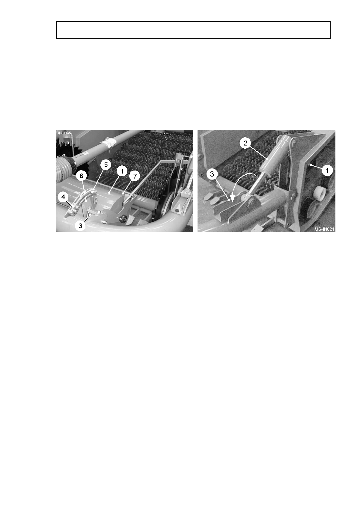
Automatic Depth Control
The machine is fitted with an automatic depth control system which ensures an even
depth of soil in the finished bed. The depth roller (item 1, fig 8) runs on top of the
preformed bed following the contours. The depth roller is linked to a depth sensor
(item 1, fig 9) and via the hydraulic valve bank actuates the depth rams (item 2, fig 9).
A depth indicator is fitted to the RH depth ram giving the operator a visual indication
of the action of the sensing system. The ram stop brackets (item 3, fig 9) must be set
in the position shown before commencing work.
The depth roller frame pivots on rubber torsion mountings (item 3, fig 8). By adjusting
these mountings it is possible to adjust the amount of pressure the roller exerts on
the soil. The pressure setting needs to be made with the machine in work so that the
relative working position of the roller and shares is correct.
1. Release the front and rear quadrant stops (item 4 & 5, fig 8) on both sides of
the roller unit.
2. Lower the machine into work until the shares are at the required digging
depth.
3. Slide the front stops (item 4, fig 8) up against front edge of the quadrant arms
(item 6, fig 8) and lightly secure.
4. Raise the machine slightly, causing the quadrant arms (item 6, fig 8) to rotate
backwards away from the front stops (item 4, fig 8), and then reposition the
front stops up against the quadrant arms and secure fully. The higher the
machine is raised prior to repositioning the front stops, the greater spring
pressure will be.
5. Lower the machine back into work and set the rear stops (item 5, fig 8)
approximately 15mm away from the rear of the quadrant arms (item 6, fig 8).
This gap allows the depth roller to drop slightly, maintaining digging depth,
when the tractor rides out of the bed onto the headland.
OPERATION
1.14
Fig 8 Fig 9

The scrapers (item 7, fig 8) should be set as close to the roller as possible without
fouling it.
Before transporting the machine on the road, reset the ram stop brackets
(item 3, fig 9).
Setting the Automatic Depth Control
1. Set the machine into work and adjust the digging depth using the ‘Digger
Share Raise/Lower’ switch on the control box.
2. Note the reading on the depth indicator.
3. Lift the machine out of work and then switch on the auto-depth system. The
LED will illuminate when the system is activated.
4. Turn the depth control dial until the depth indicator aligns with the noted
reading.
5. Note the reading on the control box display highlighted ‘AUTO DEPTH
SENSOR ANALOG’. This figure together with the reading on the depth
indicator will represent the initial depth setting. To increase the depth turn the
depth control dial clockwise. To decrease the depth turn the dial anticlockwise.
Note: For every 1mm deviated from the initial reading on the display, the
share depth will alter by 6mm.
The default screen on the control box display is the depth control and steering
indicator display.
1.15
OPERATION
Table of contents
Other Standen Water Filtration System manuals


Popular Water Filtration System manuals by other brands

EINHELL
EINHELL BT-VC500 Original operating instructions

Global Industrial
Global Industrial 641753 manual

Clean Water Systems
Clean Water Systems Fleck 9100 Installation & start?up guide

Siemens
Siemens FDCL221 manual

Miganeo
Miganeo 040385GP user manual

Beko
Beko CLEARPOINT HP100S040 Instructions for installation and operation

Pure Blue H20
Pure Blue H20 PB-TLRO4H50T instruction manual

Hydro
Hydro Up-Flo Operation and maintenance manual

Filtration Group
Filtration Group Pi 211 manual

Super
Super SK Operation manual

Clean Water Systems
Clean Water Systems 7500 Series Installation & start?up guide

Du Pont
Du Pont WFQTR13000 Series installation instructions


