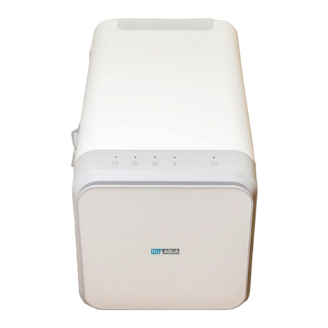
NU Aqua HC-UVC1140GPD User manual

Ultraviolet Sterilizer
Installation Manual
For NU Aqua Product ID (SKU):
HC-UVC1140GPD
HC-UVC1140GPD-SYS

Congratulations
on Your New
Ultraviolet
Sterilizer
Scan here
for link to video Watch the complete
installation guide at
nuaquasystems.com/install

Table of contents
Introduction
Conditions Page 4
Introduction Page 5
Preparation
Inspection Page 5
Recommended tools Page 5
Installation components Page 5
Quick connect guide Page 6
Tube cutting guide Page 6
Installation
UV Filter (HC-UVC1140GPD) Page 7-8
Complete UV System (HC-UVC1140GPD-SYS) Page 9
Feed water adapter Page 9
Leak stop valve Page 10
Faucet Page 11
Carbon Filter Page 12
UV Filter Page 12
Optional uv filter install Page 13
System use and care
System startup Page 13
Filter changes Page 14
Trouble shooting Page 14
Warranty Page 15-16

4
INCOMING WATER
Incoming water pressure must be between 14 PSI and 80 PSI. If your water pressure is above 80 PSI you will
need a pressure regulator for your sterilizer. Test your water pressure occasionally to make sure the system is
performing. Extremely hot or cold incoming water will damage the system and cannot be used. Do not install
where water hammer conditions exist, you should install a water hammer arrestor
LEAKS
Check the system occasionally after installation or maintenance to make sure no leaks have developed. Install
the system in a location with adequate drainage.
GENERAL
This UV sterilizer unit is for climate controlled indoor use only. Exposure to overly high or low temperature
ranges will damage the unit. Follow all of your state and local laws and codes regarding plumbing even if they
dier from what is stated in this manual. If your state law requires it or you prefer to we recommend using a
professional licensed installer or plumber who meets the requirements of this system. All O-Rings, fittings,
tubing, filter canisters, and teflon tape wear out after a certain period of time. The lifetime of your components
are subject to change with the quality of the water supplied. Use appropriate eye and face protection when
performing any drilling.
MAINTENANCE
The owner/user is obligated to properly maintain the UV sterilizer when necessary, at least every 1 year. This
includes the following:
-Physically inspect each connection and tubing.
At least every 3 years:
-Replace tubing
-Replace leak detector
LIMIT OF LIABILITY
In all circumstances, NU Aqua System’s maximum liability is limited to the purchase price of the product(s) sold.
NU Aqua Systems is not responsible or financially liable for any water damage, property damage, or personal
injury, direct or indirect, that may occur from normal or correct use of the products we sell, catastrophic failure
of the products we sell, failure to properly connect the units to water supply lines, and/or failure to understand
and observe the proper water pressure ratings and requirements for these units. Use, install and monitor all of
our products solely at your own risk. Always check all connections for leaks periodically. NU Aqua Systems is not
responsible for any leaks or water damage. In case some states do not allow the exclusion or limitation of
incidental or consequential damages, you may choose to return the system. If you choose to keep it, you insist
this exclusion still applies to you.
Conditions READ THIS FIRST
-Please pay attention to the following installation and safety recommendations:
-Read the installation manual before installing this system.

5
Welcome to the NU Aqua family! We're excited for you to experience the benefits of our premium home water
Ultraviolet Sterilizer. This guide will walk you through the installation process step-by-step, so you can have your
new system up and running in no time.
Introduction
Inspection
Once you have unpacked your new system and all of the components, please take a moment to carefully
inspect all of the fittings and tubing. Make sure that nothing has come loose during shipping. If any part appe-
ars cracked or broken, please do not proceed with installation. Instead, please contact us directly so that we
can send you a replacement part.
Email: support@nuaquasystems.com
Phone: 1(888) 621-0460
Installation components
UV Filter Combo
UV Filter Only
Recommended Tools
Phillips
screwdriver
Mounting platePower supply
Screws
Feed water adapter
UV Sterilizer Double sided
foam tape
1/4” Tubing
Undersink 1 stage carbon filter Flow restrictor Faucet
Leak detector UV Filter Kit
Razor blade 1/4” & 1/2”
Drill bits
Crescent wrench
(HC-UVC1140GPD)
(HC-UVC1140GPD-SYS)

Tubing/Fittings/
Plug Removal
If there is a retaining clip on the collet, remove it
first. Push down on the collet to unlock the tubing,
then gently pull the tube, fitting, or plug to remove
it.
Quick Connect Guide
Install or Remove
Retaining Clips
To lock a tube in it’s fitting make sure that it is fully
inserted. Slide the retaining clip between the collet
and fitting. Before tubing can be removed from a
fitting you must remove this clip first. To remove the
retaining clip simply pull the clip away from the
fitting until it slide completely out.
Insert Tubing
Push the tubing straight and level into the fitting.
When inserting the tubing make sure you push until
it stops to ensure the lock is activated. The tubing
will travel 5/8” into the fitting. Gently pull on the
tubing to check that the lock is activated.
How to Cut Tubing
When cutting the supplied tubing its important to
use a sharp razor blade. Place the tubing on a flat
surface and cut straight through the tubing. All cuts
to your tubing must be perfectly straight to ensure
the best connections.
NOTE:
Always check each connection
to make sure its secure
NOTE:
Improperly cut tubing may cause
a leak
Plug
Collet
Locking
Clip
Pull Up
Hold
Down
Unlocked Locked
5/8” 5/8”
OK
X
6

7
NOTE:
Always check each connection
to make sure its secure
NOTE:
Improperly cut tubing may cause
a leak
Installation
UV Filter Only
Mounting
There are two mounting options for your UV filter.
Option one is a adhesive pad. This is the easiest
option but will be less secure. Option two is a hard
mount that is more secure and uses screws to
attach to the inside of your cabinet.
Adhesive
1. Select the location you want to install your UV
Filter. This should be atleast 8 inches above the
bottom of the cabinet.
2. Peel o the backing of the adhesive pad.
3. Firmly press the adhesive pad against the
cabinet wall.
4. Peel o the front cover of the adhesive pad.
Press the mounting plate firmly against the
pad to secure it.
5. Hang the UV water filter on the mounting plate
studs.
Hard Mount
1. Select the location you want to install your UV
Filter. This should be atleast 8 inches above the
bottom of the cabinet.
2. Secure the mounting plate directly to the
cabinet wall using the supplied screws
3. Hang the UV water filter on the mounting plate
studs.
Connections
1. Connect the pure water outlet from your
filtration system to the quick connect inlet on
the bottom of the UV filter. Secure the tubing in
place with the retainer clip. You may need to
cut excess tubing.
2. Connect the supplied tubing to the outlet
located on the bottom of your UV filter. Secure
the tubing in place with the retainer clip.
3. Connect the tubing from the outlet to your
faucet. You may need to cut excess tubing.
4. Connect the power supply to the port located
on the bottom of the UV filter.
5. Now to turn the system on connect the power
supply to a wall outlet.
Wall
Wall
Wall
Screw
Adhesive pad
Mounting Plate
Mounting Plate
Mounting Plate
Inlet
Outlet
Power cord
Stud
Stud
(HC-UVC1140GPD)

8
Installation
System startup
1. Connect the power supply to the port located
on the bottom of the UV filter.
2. Now to turn the system on connect the power
supply to a wall outlet.
System functions
The red light on the bottom of the system indicates
that it is powered on. The green light on the front of
the system indicates that the UV light is on and will
only turn on when water is drawn from the system.
Red light: powered on
Green light: UV light on
WARNING: Check system for leaks
every day for one week after
installation.

9
Installation
Complete System
Feed Water Adapter
1. Locate vand turn o the cold water
valve under your sink. Next turn on the
cold water faucet to drain any remai-
ning water in the line
2. Place a towel below your cold water
valve to catch any remaining water in
the line. Loosen the nut on the water
line where it is attached to the valve.
Feed water adapter can be installed in
either location A or B as illustrated in
the diagram”
3. Wrap the threads of the water valve
and feed water adapter 8-10 times with
teflon tap. using a adjustable wrench
secure the feed water adapter onto the
cold water valve and the water line to
the feed water adapter.
4. Turn the feed water valve to the o
position for the remainder of the instal-
lation process.
5. Insert one end of your white tubing
into the quick connect fitting on your
feed water adapter. Secure in place
with a retaining clip.
WARNINGS:
Only connect to cold water line.
Hot water will damage your system.
WARNINGS:
Turn the hot water valve o when
installing on a single handed faucet.
1/2” Connection 3/8” Connection Open Closed
Adapter
Adapter
(HC-UVC1140GPD-SYS)

10
Installation
Leak stop valve installation
1. Locate the lowest point within your cabinet or installa-
tion location. Using the included screws, secure your
leak stop valve in this location
2. Locate the white tubing coming from the feed water
adapter and cut it near the location of the leak stopper.
Connect the end of the white tubing coming from the
feed water adapter to the quick connect on the leak
stop valve labeled “in”.
3. Take o the plastic wrap o the leak cartridge and
place it inside the leak stop valve as shown.
4. Turn the leak stop valve switch down to put it in the on
position.
WARNING:
failure to install Leak Stop Valve will
void Warranty
NOTE:
it may be best to insert the cartridge after
the initial startup is complete
Flow Closed
Position
Flow Open
Position

11
Installation
Faucet Installation
Drilling
If your sink has a existing hole this can be used for
your faucet. If you have to drill a new hole follow the
steps below.
1. Locate the section on your countertop to install
your faucet. Using plumbers clay form a ring around
the section you will be drilling. This will be used to
retain water for the drilling process.
2. Fill the ring with water. Using a diamond tip hole
saw drill bit slowly begin drilling. Apply light, and even
pressure and let the drill do the work.
1. Locate the section on your countertop to install
your faucet and drill a 1/4” pilot hole. Once comple-
tely drilled through switch to a 1/2” drill bit and re-drill
the same hole.
Granite / Marble / Quartz sinks
Stainless Sink
Keep the drill bit and hole wet
during the drilling process
1. Slide the base plate on the threaded faucet
stem. Insert the faucet into the hole in your coun-
tertop.
2. Under your sink slide the rubber washer on the
faucet stem. Secure the faucet in place by hand
with the wing nut.
Installation
TYPE A
1. Connect the white tubing to the quick connect
fitting on your faucet adapter.
2. Screw the faucet adapter onto the threaded
faucet stem.
TYPE B
1. Slide the compression nut with the open end facing
upwards down your white tubing. Follow the nut with
your sleeve.
2. Slide the insert into the opening of your tubing
firmly.
3. Insert your tubing into the faucet stem and tighten
the compression nut to secure it in place. Do not over
tighten.
Tubing Connection
TYPE B
TYPE A
OpenClosed
Open and Closed Position
Base Plate
Threaded Faucet
Stem
Rubber Washer
Faucer Adapter
Wing nut
Insert
Sleeve
Compression Nut
1/4” Tube
1/4” Tube

12
Installation
Filter Installation
1. Mount the filter with the screws provi-
ded in a location that is close to your
leak detector.
2. Attach the tubing coming from the
outlet of your leak detector to the inlet
of the carbon filter. Attach the retaining
clip to secure the tubing in place.
UV Filter Installation
Mounting
There are two mounting options for your UV filter.
Option one is a adhesive pad. This is the easiest
option but will be less secure. Option two is a hard
mount that is more secure and uses screws to
attach to the inside of your cabinet.
Adhesive
1. Select the location you want to install your UV
Filter. This should be atleast 8 inches above the
bottom of the cabinet and close to your
carbon filter.
2. Peel o the backing of the adhesive pad.
3. Firmly press the adhesive pad against the
cabinet wall.
4. Peel o the front cover of the adhesive pad.
Press the mounting plate firmly against the
pad to secure it.
5. Hang the UV water filter on the mounting plate
studs.
Hard Mount
1. Select the location you want to install your UV
Filter. This should be atleast 8 inches above the
bottom of the cabinet.
2. Secure the mounting plate directly to the
cabinet wall using the supplied screws
3. Hang the UV water filter on the mounting plate
studs.
Wall
Adhesive pad
Mounting Plate
Stud
Wall
Screw
Mounting Plate
Stud
Wall
Mounting Plate

13
1. Cut a length of tubing that will connect between
the outlet of the carbon filter and your UV filter.
2. Install this tubing into the outlet of the carbon
filter and the inlet of the UV filter. Secure the tubing
in place with retainer clips on both connections.
3. Cut a length of tubing that will connect between
the outlet of the UV filter and the faucet. Make a
cut in this tubing at a minimum of 6” past the
outlet of the UV filter.
4. Connect these two pieces of tubing with the flow
restrictor. Make sure the arrow is pointed in the
direction of the faucet.
5. Connect this tubing to the outlet of the UV filter
and faucet. Secure the tubing in place with
retainer clips.
Installation
UV Filter Connections
System Startup
1. Check every quick connect fitting to ensure it’s fully inserted.
2. Plug in the power supply into the base of the UV filter and
plug it into a wall outlet. Make sure this outlet is not on a
switch for your garbage disposal.
3. Open the the cold water valve then then slowly open the
feed water valve. Let the system fully pressurize and check
for leaks at each connection. If younotice any leaks close
the valve and reset the connection. If this does not
resolve the issue contact customer support.
4. Open the faucet and allow the system to run for 3 minutes.
Your water may appear dark and cloudy. This is normal during
the flushing process of a new filter.
Your installation is now complete.
System functions
The red light on the bottom of the system indicates
that it is powered on. The green light on the front of
the system indicates that the UV light is on and will
only turn on when water is drawn from the system.
Red light: powered on
Green light: UV light on

14
Maintenance
The NU Aqua UV Filter is utilizes industrial grade
LEDs instead of traditional style bulbs. This provi-
des years of maintenance free use.
The carbon filter in your system requires replace-
ment every 8-12 months or 5,000 gallons.
1. First turn the feed water valve to the o
position and open the faucet to relieve any
pressure in the system.
2. Twist the filter counterclockwise to release it
from housing and discard the old filter.
3. Inspect your new filters top o-ring and make
sure its seated in place.
4. Install your new filter into the housing and twist
clockwise to lock into place.
5. Slowly open your feed water valve and check
for leaks as the system pressurizes.
6. Open the faucet and allow the system to run
for 3 minutes to flush any loose carbon mate-
rial. Your water may have small black particles
during this process and will go away.
WARNING: Your water may appear
cloudy after a filter change. This is
caused by air bubbles and will go away.
UV Filter
Carbon Filter
Troubleshooting
No or low water flow
UV light o
Cloud water
• Open cold water valve and feed water
valve fully
• Check flow restrictors arrow points
towards faucet
• Try power supply on dierent outlet
• Make sure outlet is not on garbage
disposal switch
• Continue using system. This is normal
and go away with use as the air trapped
in system goes away
• Closed water valves
• flow restrictor installed wrong
direction
• Power supply not
receiving power
• Bubbles caused by air in system
Problem Causes Solution

15
Limited Product Warranty
SCOPE
NU Aqua Systems takes pride in selling the highest quality UV Filter (“Product”) on the market. As such, NU Aqua Systems
expressly warrants to the original purchaser that, for a period of two (2) years from the date of purchase, the Product will be
reasonably free of defects in materials and workmanship. Within that two (2) year period from the original purchase, NU Aqua
Systems will, at its option, repair or replace the Product without charge, or refund the cost of the Product, if the Product fails or
does not perform as warranted solely due to a manufacturing defect within the warranty period, subject to the limitations and
exclusions set forth in this Limited Product Warranty. This Limited Product Warranty only applies when the Product is used,
stored, handled, fabricated and/or installed in the manner recommended by NU Aqua Systems in the Installation Instruction &
Owner's Manual (“Manual”).
REPAIR OR REPLACEMENT
Repair or replacement during this two (2) year warranty does not include labor charges, freight charges or any other local
charges from third parties other than NU Aqua Systems, unless NU Aqua Systems expressly approves such charges in writing.
During the entire two (2) year warranty, NU Aqua Systems's obligation to repair or replace shall further be limited to repair or
replacement with the styles, models, products, colors, etc. of the Product that are available at the time of the repair or replace-
ment, and shall be limited to the repair or replacement of only the specific Product that fails due to a manufacturing defect.
Any repaired or replaced product shall also remain subject to the original two (2) year warranty from the date of the original
purchase, and any repair or replacement shall not extend the original warranty period in any manner or start a new warranty
period.
CONDITIONS OF VALIDITY OF THIS LIMITED PRODUCT WARRANTY
Even though the Product has extremely high endurance for operating conditions such as pH, maximum TDS, temperature, and
optimum water pressure,
THIS LIMITED PRODUCT WARRANTY SHALL ONLY BE VALID IF:
1. The Product is operated within the confines of the following feed water conditions:
• Water Pressure: 14 - 80 PSI
• PH Range: 2-11 Max. TDS: 1000 PPM Water Temperature: 40°-100° F SDI: 5
Any information or suggestion by NU Aqua Systems with respect to the Product concerning applications, specifications or
compliance with codes and standards is provided solely for your convenient reference and is made without any representation
as to accuracy or suitability. You must verify and test the suitability of any information with respect to the Product for your
specific application.
NON-COVERED DEFECTS
THIS LIMITED PRODUCT WARRANTY DOES NOT COVER DEFECTS CAUSED BY:
1. Improper storage, installation, maintenance, handling, use and/or alterations of the Product, including, but not limited to,
noncompliance with the installation, maintenance and standard operation conditions stated in the Manual and this Limited
Product Warranty.
2. Unreasonable use, unintended use, or misuse of the Product for something other than its intended purpose as a reverse
osmosis system.
3. Use of replacement parts, filters, membranes or other accessories that are not sold or manufactured by NU Aqua Systems
for use with this particular Product.
4. Damage not resulting from manufacturing defects that occur while the Product is in the original purchaser's possession.
5. Installation of the Product with known or visible manufacturing defects at the time of installation.
6. Damage caused by freezing, flood, fire or Act of God.

16
Conditions That Render This Limited Product Warranty Void
THIS LIMITED PRODUCT WARRANTY SHALL BE VOID IF:
1. The Product is not operated in compliance with normal municipal water conditions for which the particular model of this
Product is intended.
2. The person seeking to invoke the warranty is not the original purchaser. That is, this Limited Product Warranty only extends
to original purchasers.
3. The Product is purchased used. That is, this Limited Product Warranty only covers new products.
4. The Product is purchased from someone other than NU Aqua Systems or one of NU Aqua Systems authorized dealers. This
is because, unless the Product was sold by NU Aqua Systems or one of its authorized dealers, NU Aqua Systems cannot verify
or guarantee the integrity or authenticity of the Product.
GENERAL CONDITIONS
The warranties set forth herein are the only warranties made by NU Aqua Systems in connection with the product. NU Aqua
Systems cannot and does not make any implied or express warranties with respect to the product, and disclaims all other
warranties, including, but not limited to, any warranty of merchantability or fitness for a particular purpose. Products sold by NU
Aqua Systems are sold only to the specifications specifically set forth by NU Aqua Systems in writing. Other than the limited
product warranty set forth herein, NU Aqua Systems makes no other warranties, express or implied. NU Aqua System’s sole
obligation under this warranty shall be repair or replacement of a non-conforming product or parts of the product, or at the
option of NU Aqua Systems, return of the product and a refund of the purchase price. Buyer assumes all risk whatsoever as to
the result of the use of the product purchased, whether used singularly or in combination with any other products or substances.
No claim by the buyer/owner of any kind, including claims for indemnification, shall be greater in amount than the purchase
price of the products in respect to which damages are claimed. In no event shall NU Aqua Systems be liable to buyer/owner in
tort, contract or otherwise, for any special, indirect, incidental, consequential, reliance, statutory, special, punitive or exemplary
damages, including, but not limited to, lost profits, loss of use, loss of time, inconvenience, damage to goodwill or reputation, or
loss of data, even if advised of the possibility of such damages or such damages could have been reasonably foreseen, in
connection with, arising out of, or as a result of, the sale, delivery, servicing, use or loss of use of the products sold hereunder, or
for any liability of buyer to any third party with respect thereto.
In case some states do not allow the exclusion or limitation of incidental or consequential damages, you may choose to return
the Product. If you choose to keep it, you insist this exclusion still applies to you.
OBTAINING WARRANTY COVERAGE OR GENERAL INQUIRIES
If coverage is available, you may obtain coverage under this Limited Product Warranty by providing NU Aqua Systems with
proof of original purchase, and that you are the original purchaser. For service under this Limited Product Warranty, you must
notify NU Aqua Systems by phone at 1-888-621-0460, by email at [email protected], or in writing at 735 Challenger
Street Brea, CA 92821. In making the claim, please provide your name, address, phone number, a description of the product
involved, and an explanation of the defect.
This manual suits for next models
1
Table of contents
Other NU Aqua Water Filtration System manuals
Popular Water Filtration System manuals by other brands

Beko
Beko CLEARPOINT S040 Instructions for installation and operation

Aquasana
Aquasana AQ-CWM-RB1 Setup instructions

King Industrial
King Industrial KDCF-8500HEPA instruction manual

Panasonic
Panasonic ET-RFF200C operating instructions

Valrom Industrie
Valrom Industrie aquaPUR 4 UF instructions

Vertex Water Products
Vertex Water Products PureWaterMachine PT-4.0 Owners & installation manual