Standen MEGASTAR GEN-2 Service manual

MEGASTAR GEN-2
De-stoner / De-clodder
Standen Engineering Limited.
Hereward Works,
Station Road, Ely,
Cambridgeshire.
CB7 4BP
England.
Tel: 01353 661111 www.standen.co.uk Fax: 01353 662370


On delivery check that the machine is as ordered and has not been damaged in
transit. Please report any shortfall to your Standen dealer.
The contents of this handbook, although correct at the time of publication, may be
subject to alteration by the manufacturers without prior notice.
Standen Engineering Limited operates a policy of continual product development.
Therefore, some illustrations and/or text within this publication may differ from your
machine.
The copyright of this handbook is the property of Standen Engineering Limited,
Hereward Works, Station Road, Ely, Cambridgeshire. CB7 4BP. This handbook is
issued on the condition that it must not be used, copied or exhibited without their
written permission.
IMPORTANT
This oper
ator’s handbook should be regarded as part of the
machine. Suppliers of both new and second-
hand machines are
advised to retain documentary evidence that this handbook was
supplied along with the machine.
On installation of the machine (i.e. starting off
in the field), the New
Machine Installation Record Card should be completed by the
dealer/distributor and be countersigned by the customer. The
document is proof that the correct procedures have been followed.
The New Machine Installation Record Card shou
ld be returned to
Standen Engineering Limited within 7 days of installation. Failure to
do so may invalidate the machine warranty.


INTRODUCTION
Introduction to the Handbook 1.1
Warranty 1.1
Replacement Parts 1.2
SAFETY PRECAUTIONS
Safety 1.3
HSE Information Sheet 1.5
INSTALLATION
Tractor Wheel Settings 1.7
Drawbar 1.7
PTO Shaft 1.8
Hydraulic Connection 1.9
Open/Closed Centre Hydraulics 1.9
OPERATION
Electrical Control System 1.10
Machine Wheel Settings 1.12
Manual/Automatic Depth Control 1.14
Discs 1.14
Shares 1.15
Vari-Flow Web 1.15
Clod Mat 1.15
Boulder Box 1.16
Cross Conveyor 1.16
Rhizome Discharge Elevator 1.17
Axle Steering 1.17
Hydraulically Damped Drawbar 1.17
Braked Axles 1.18
OPERATION IN THE FIELD
Starting Off Your Machine 1.19
Getting The Best Results From Your Machine 1.19
Star Spacing 1.20
Star Speed 1.20
MAINTENANCE
New Machines 1.22
Lubrication 1.22
Drive Belt Maintenance 1.23
Electrical System Maintenance 1.23
Hydraulic System Maintenance 1.23
Residual Hydraulic Pressure Dump Procedure 1.24
Testing The Auto-Depth Control Circuit 1.25
Testing The Axle Auto-Centring Circuit 1.25
Proximity Sensor Adjustment 1.26
Proximity Sensor Operation 1.26
Daily Maintenance 1.27
Weekly Maintenance 1.27
Annual Maintenance 1.27
Out of Season Storage 1.28
Drive Belt Adjustment Sheets 1.29
SPECIFICATIONS
Machine Dimensions 1.32
Machine Weight 1.32
Technical Data 1.32
CONTENTS

Introduction to the Handbook
This handbook provides the information for the operation, adjustment and
maintenance of your Standen Megastar Gen-2. To enable you to achieve the best
results from the machine, the manufacturer recommends that you read the handbook
thoroughly prior to using the machine for the first time.
Record below the details of your machine.
Dealers name...............................................................................…………….
Address......................................................................................................
.................................................................................................................
Telephone number.................................................................................…….
Machine serial number...............................................................................…
Date purchased............................................................................................
Date started work........................................................................................
This symbol indicates important safety messages within this handbook.
When you see this symbol, be alert to the possibility of injury to yourself
or others and/or damage to the machine and carefully read the message
that follows.
Throughout this handbook the terms 'front', 'rear', 'left-hand' (LH) and 'right-hand'
(RH) are derived from the tractor driver’s position facing forward in the normal
direction of travel.
Adjustments to the machine may have to be made singly or in combination according
soil conditions. Always allow the machine to settle to a new setting before making
further adjustments.
Recommended lubrication and maintenance instructions are included in this
handbook and if followed will help to keep the machine in a safe working condition.
Warranty
Should the machine suffer any faults or defects within the warranty period, please
contact your dealer. The warranty shall be effective only if the dealer is informed of
any such defect as soon as practicable upon discovery.
1.1
INTRODUCTION

Replacement Parts
Recommended replacement parts are designed for your machine and have the full
backing of the warranty. Only when recommended parts are used can responsibility
be considered under the terms of the warranty.
Section 3 of this handbook contains lists of spare parts available through your
Standen Agents. Each illustration shows a complete unit or assembly in exploded
form. Standen's policy of continual product development means that components or
even complete assemblies are redesigned from time to time. Where possible the
modifications are shown in the remarks column.
The first printing of each page in the spare parts section is identified as issue 1 at the
foot of the page. When a complete unit or assembly has been redesigned the
appropriate pages are revised and printed as issue 2. The revised pages are filed
behind the existing issue so that a complete modification history is gradually built up.
When using an illustration and parts list it is essential that both are of the same issue.
Always quote the full serial number of your machine when ordering spare
parts.
INTRODUCTION
1.2

Safety
The Standen Megastar Gen-2 has been designed to comply with current Safety
Regulations. However, as with all machinery there will be inherent dangers whilst
operating and carrying out maintenance on the machine. The following list of
precautions should therefore be brought to the attention of all persons operating and
working on the machine. The list is not exhaustive. All machinery is potentially
dangerous and great care must be exercised by the operators at all times. Standen
Engineering Limited will not accept liability for damage or injury caused by their
products except when such liability is specifically imposed by English statute.
The machine must never be operated by untrained personnel or
children.
Always check that the machine has been correctly mounted to the
tractor before setting off on operations.
Never set machinery in motion before ensuring that everyone in the
vicinity is aware of your intentions.
Never allow children or animals in the vicinity where machines are
working and never allow anyone to ride on the machine.
In dry, dusty conditions it is prudent to use a tractor with an enclosed
cab.
Never attempt to fit drive chains or drive belts to the machine while the
drive sprockets or pulleys are in motion.
Normal safe working procedures should be adopted at all times.
Reduce speed when transporting the machine on sloping ground.
Do not work on ground where there is a possibility of overturning or
across steep slopes.
The working area should be kept clear and free of obstructions at all
times. Be alert for hidden obstructions. Should the machine hit an
obstruction, stop and check for damage before proceeding.
On machines fitted with a discharge elevator, when folding and
unfolding, ensure there are no overhead restrictions and that everyone
in the vicinity is aware of your intentions.
Wear substantial or proper safety footwear. Avoid loose clothing near
moving parts. Wear gloves when handling the implement or parts with
sharp edges.
Before carrying out any work on the machine, lower the machine to the
ground, switch off the tractor engine, apply the handbrake, remove the
ignition key and disconnect the PTO shaft.
1.3
SAFETY PRECAUTIONS

The operator must not leave the tractor seat until the machine has been
lowered to the ground, the tractor engine switched off, the handbrake
applied and the ignition key removed.
Never reverse or turn unless the machine is in the raised position.
All guards, covers, warning transfers and safety devices must be
correctly fitted and operable at all times.
Inspect the machine on a regular basis and replace damaged or worn
parts as necessary.
Never operate the machine in a state of disrepair.
Only transport the machine at a speed suitable to the prevailing
conditions. Be aware of the weight and overall length of the machine at
all times.
Before working on the machine, all free moving parts should be locked
to prevent them moving.
Regularly lubricate the machine as per the operator’s handbook and
check the tightness of all nuts and bolts.
Always use mechanical or additional help when lifting heavy parts.
Regularly check hydraulic hoses for chafing or damage and replace as
necessary.
Care must be taken when carrying out any work on the hydraulic
system. Even when stopped and disconnected from the tractor, residual
pressure will exist within the hydraulic system. Therefore, before
commencing any work on the hydraulics ensure that the system is free
of residual pressure by carrying out the ‘pressure dump’ procedure
outlined within this handbook.
Before transporting the machine on a public road, set the hydraulic
levelling to its lowest position, fully raise the shares, lock the cross
conveyor into the transport position, set the drawbar and steering to the
straight-ahead position and switch off the control box to avoid
inadvertently operating any machine services. Finally, ensure road
lights are clean and in good working order.
Safety is the responsibility of the persons working with this
machine. Think "safety" at all times. Read and remember the
contents of this handbook.
SAFETY PRECAUTIONS
1.4

1.5
SAFETY PRECAUTIONS
SAFETY PRECAUTIONS
1.6

Tractor Wheel Settings
Both front and rear tractor wheels must be set to run down the centre of the
wheelings and must span the bed being lifted. Consult your tractor handbook for the
correct procedure for setting the tractor wheels.
When carrying out wheel adjustments, always place the jack on firm
ground under a solid part of the tractor. Before removing a wheel, place
a stout support under the tractor frame in case the jack should become
dislodged.
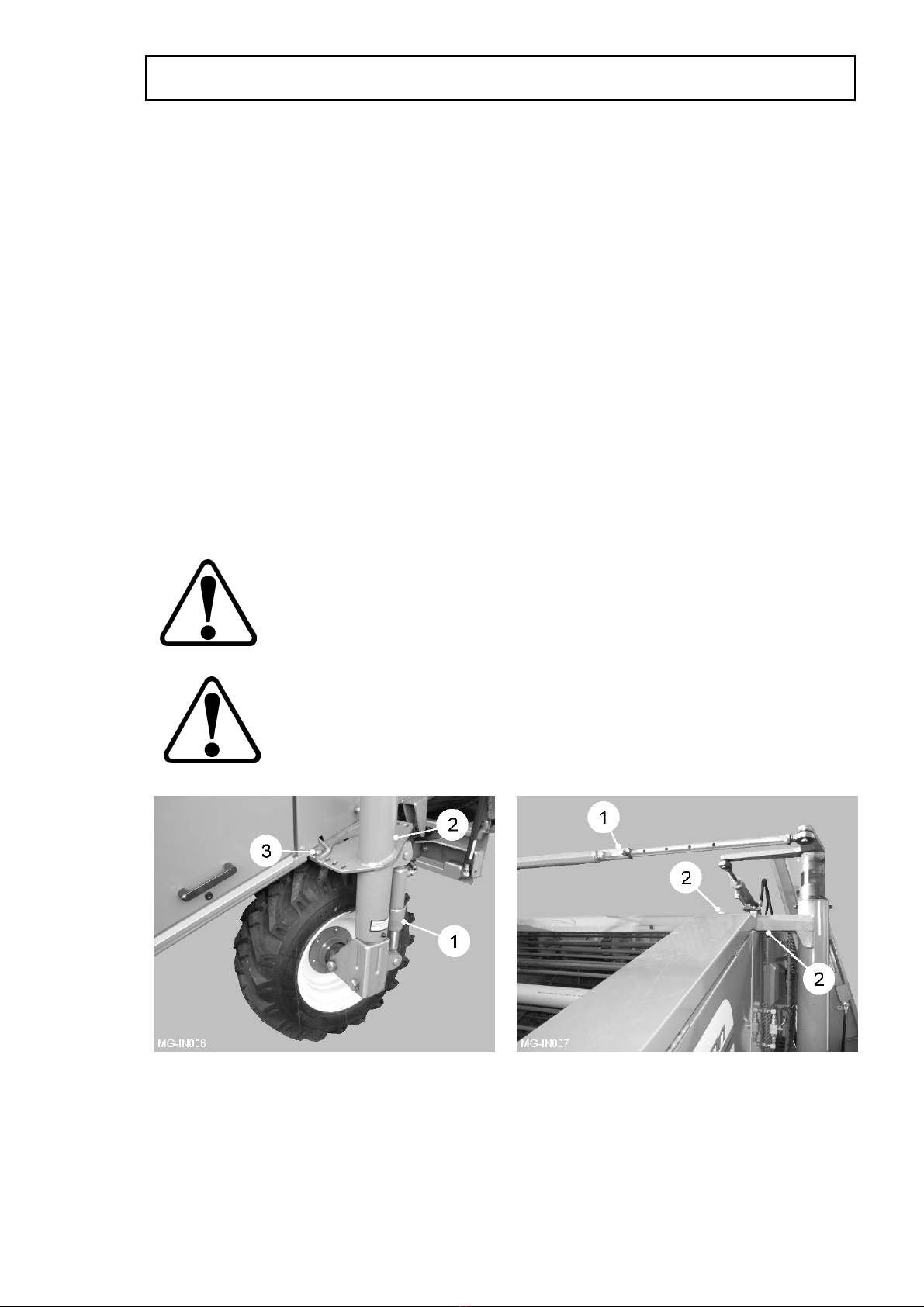
Drawbar
The drawbar (item 1, fig 1) is designed to be attached to the tractor’s swinging
drawbar. The tractor drawbar should be fixed in its central position. Consult the
tractor manufacturer’s handbook for details. The machine drawbar eye should be
checked regularly to ensure it is free moving and kept greased to prevent excessive
wear.
The machine must be connected to the tractor using the proper type
and size of pin which should be securely fixed by the correct means.
This will ensure that it cannot be accidentally pulled or pushed out of
place whilst the machine is in use.
The stand (item 2, fig 1) is provided so that the machine is held at a suitable height
for safely coupling to the tractor. To adjust the height, connect the hydraulic hoses to
the tractor and open the drawbar transport lock valve (item 3, fig 1). Operate the
control box share depth control to achieve the correct drawbar height.
Once securely attached to the tractor, raise the machine and remove the stand
locking pin (item 4, fig 1). Store the stand on the LH side of the front chassis using
the locking pin.
When disconnecting from the tractor always ensure the stand is
positioned on firm ground. Both wheels should be chocked at front and
rear before removing the drawbar pin. Always store the stand on the
machine. You never know when it will be needed.
1.7
INSTALLATION
Fig 1

minimum1/2 overlap
PTO Shaft
The machine is designed to operate with the tractors 540 rpm, 6 spline, 1 3/8” PTO
output shaft.
PTO speeds greater than 540 rpm will cause damage to the system
and if exceeded may invalidate the warranty.
Fit the two halves of the PTO shaft onto their respective drive shafts on the machine
and tractor. Check the shaft length by turning the tractor fully in both directions with
the machine in its working position while attached to the tractor’s pick-up hitch.
Ensure the sliding tubes, when fully extended, have an overlap at least half the
closed length (see figure 2). Ensure that the ends of the sliding tubes when at the
shortest point are not in contact with other parts of the PTO shaft. If necessary,
shorten both tubes and guards equally to achieve end clearance at the minimum
length position.
Make sure that the drive shaft is fitted correctly and that the lock pins are engaged.
All the parts of the PTO shaft, especially the guards, must be kept in good order.
Check regularly that the guard is undamaged and fully protects the whole of the
shaft, and that both the guard and the shaft will telescope freely.
If it is possible to engage the inner and outer parts of a drive in more than two
positions circumferentially then make sure that the universal joint yokes are correctly
aligned.
Check that when in the continuous working position, the drive shaft is not at an angle
of more than 20° from the PTO centre line. The angle between the drive shaft and
the input and output shafts should be equal.
Ensure that the safety chains (item 1, fig 2) used to prevent the guards from turning,
are fixed to the tractor and implement in such a way that they will not be stretched
when the drive shaft is at maximum articulation. When disconnected from the tractor,
position the PTO shaft on the drawbar rest (item 5, fig 1).
INSTALLATION
1.8
1
Fig 2

Hydraulic Connection
The feed and return hoses from the machine must be connected to the respective
external service connections of the tractor hydraulic system. Both feed and return
hoses have labels with arrows indicating the direction of oil flow.
The tractor hydraulic system must be set to constant pumping. Consult the tractor
manufacturers handbook for details about connecting external equipment to the
hydraulic system and hydraulic pump settings.
Required oil flow from tractor system minimum 70 ltr/min
(Set to constant pump) maximum 100 ltr/min
(For flows greater than 100 ltr/min consult your officially appointed Standen dealer)
There must no restriction in this return oil. Ensure that there is a full flow return, or
even better return straight back into the tractor gearbox. Consult your tractor
handbook or dealer for further information.
Open/Closed Centre Hydraulics
Two types of hydraulic system are currently in use by tractor manufacturers, namely
OPEN CENTRE or CLOSED CENTRE configurations. Consult the tractor
manufacturers handbook or dealer for further information.
The main hydraulic valve bank, situated behind the rear LH guard of the machine,
incorporates an adjustable screw (item 1, fig 3) which enables easy changing from
closed to open centre and vice versa. For closed centre configuration tractors, turn
the screw clockwise until fully closed. For open centre, turn the screw anticlockwise
until fully out.
1.9
INSTALLATION
Fig 3

Electrical Control System
Mount the control box (item 1, fig 4) securely inside the tractor cab in a position
where it is comfortable to operate when seated. Connect the machine control
harness between the control box and machine ensuring it is safely routed into the
tractor cab. Connect the control box power supply cable to the tractor’s 12V d.c.
electrical plug (if fitted) or directly to the tractor battery, blue lead to negative (-)
brown lead to positive (+). The electrical equipment should only be connected to
a 12V d.c. supply.
Do not leave or store the control box outside in the open and always
disconnect the control box from the tractor electrical supply when not in
use, so avoiding the possibility of draining the battery.
Control for the major functions of the Megastar Gen-2 are provided electronically by
the switches mounted on the control box. The function of each switch is listed below.
Hydraulic Drawbar (optional)
The hydraulic drawbar push button activates/deactivates the hydraulically damped
drawbar system. The LED is illuminated when the system is switched on.
Digger Share Raise/Lower
The 3 position spring toggle switch manually raises/lowers the digger assembly
increasing/decreasing the depth of the shares below the soil. Releasing the switch to
the central position leaves the share depth at the present setting. Setting the switch
to the locked lower position enables the depth ram to free float.
Auto-Depth
With the digger share switch set in the lower position, the push button
activates/deactivates the digger share auto-depth system. The share depth is
automatically adjusted by the movement of the depth roller. The LED is illuminated
when the system is switched on. Operating the manual digger share raise/lower
switch will override the auto-depth system. The auto-depth indicator lights show
when the depth sensors are operating.
OPERATION
1.10
Fig 4
Axle Steering
The axle steer switch manually steers the machine wheels left/right. The auto-centre
button when pressed operates the self-centring circuit to automatically set the wheels
to the straight-ahead position.
Only operate the steering while the machine is moving or some of the
steering components may be damaged.
Machine Level
The two axle level switches operate the LH and RH levelling rams (item 1, fig 5).
Moving the switch left will lower the LH side of the machine. Moving the switch to the
right will raise the machine.
Cross Conveyor Side Shift & Fold
The switch marked ‘lift to operate’ sets the adjacent 3 position toggle switch to
conveyor side-shift function or to conveyor fold function.
Never operate the side shift function with the conveyor folded. Ensure
the conveyor is moved fully to the LH discharge position before folding
up the conveyor.
Cross Conveyor Drive
The switch marked ‘cross conveyor drive’ starts/stops the cross conveyor web to
discharge to the LH or RH side of the machine. With the switch in the centre position
the discharge web is stopped. Move the switch up to discharge to the RH side of the
machine, or down to discharge to the LH side. The corresponding LED will illuminate.
The dial marked ‘cross conveyor speed control’ sets the speed of the discharge web.
Turn the dial clockwise to increase or anticlockwise to decrease the speed.
Rhizome Discharge Elevator Fold (optional)
An optional discharge elevator can be fitted in place of the cross conveyor. The 3
position spring toggle switch sets the elevator from the transport to discharge
position.
Before operating the discharge elevator, ensure everyone in the vicinity
is aware of your intentions and that there are no overhead restrictions.
See the HSE information sheet within this handbook.
Rhizome Discharge Elevator Drive (optional)
The switch marked ‘discharge elevator drive’ starts/stops the elevator web to
discharge the lifted material into a trailer running alongside. The dial marked ‘elevator
speed control’ sets the speed of the discharge web. Turn the dial clockwise to
increase or anticlockwise to decrease the speed.
Clod Mat (optional)
The switch marked ‘clod mat’ raises/lowers the clod mat blocks. Move the switch up
to raise or down to lower the clod mat.
1.11
OPERATION
Vari-Flow Web (optional)
The push button starts/stops the vari-web. The LED is illuminated when the unit is
running. The dial increases/decreases the speed of the web. Turn the dial clockwise
to increase or anticlockwise to decrease the speed.
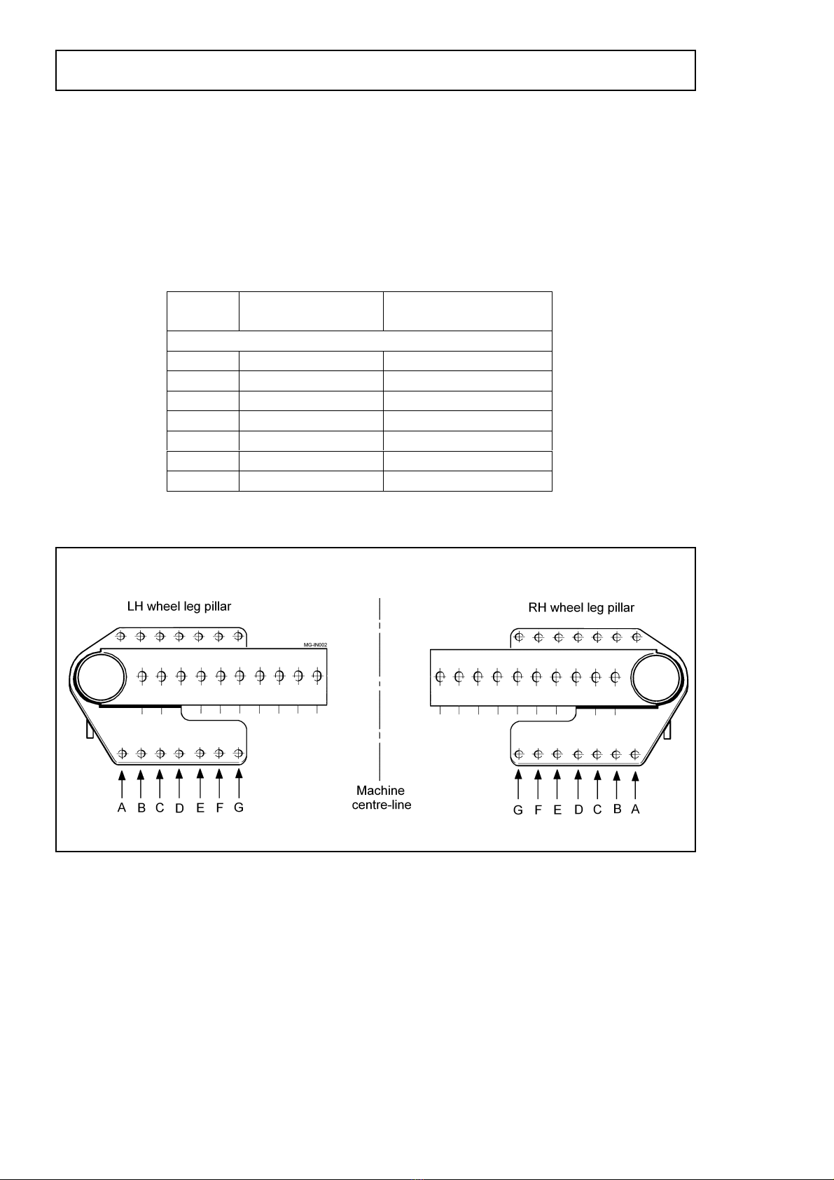
Machine Wheel Settings
The machine wheels must be set for work in a specific bed width. The wheels should
be set to match the tractor wheels.
Each wheel is carried by a wheel leg pillar (item 2, fig 5) The pillars have a top and
bottom flange plate containing a series of fixing holes. Moving the pillars in or out
adjusts the wheel centres to suit the selected bed width. Both wheel legs must be set
to the same hole positions so that the wheels remain symmetrical about the centre-
line of the machine (see figure 7). Lifting equipment must be used when setting the
wheels.
Before commencing axle adjustment, ensure adequate jacks, axle
stands of minimum 2500 kg capacity, wheel chocks and suitable lifting
equipment are available.
It is important that the machine is correctly fitted to the tractor and that
the tractor handbrake is applied whilst axle adjustments are made.
Place chocks at the front and rear of the opposite side wheel to the one being
adjusted. Jack up the machine and place an axle stands under the chassis and lower
the jack to allow the axle stands to take the weight of the machine.
OPERATION
1.12
Fig 5 Fig 6
Release the track rod locking bolts (item 1, fig 6) and remove the flange plate
mounting bolts (item 3, fig 5 & item 2, fig 6). Using lifting equipment, carefully slide
the leg pillar to the required position. Refit the mounting bolts (item 3, fig 5 & item 2,
fig 6) through the relevant hole in the flange plates. Repeat the procedure for the
opposite wheel. Finally, set the track rod to the correct length and secure using the
locking bolts. Ensure all nuts and bolts are fully tightened after adjustments have
been completed.
Machine with
Unbraked Axles
Machine with
Braked Axles
A Transport / 60” Transport
B 64” 60”
C 68” 64”
D 72” 68”
E 76” 72”
F 80” 76”
G - 80”
1.1
3
OPERATION
Fig 7

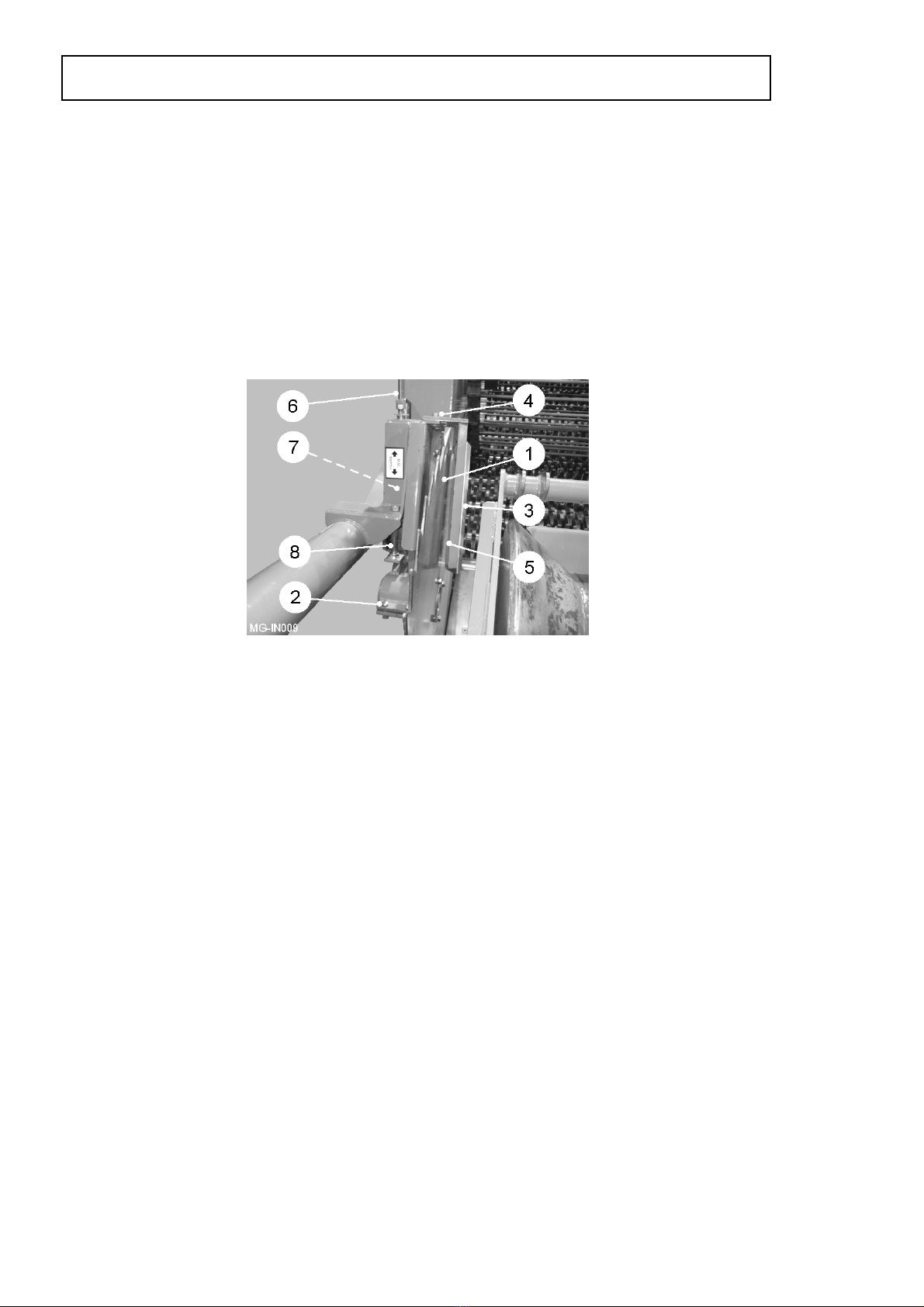
Manual/Automatic Depth Control
Manual/automatic depth control ensures an even depth of soil in the finished bed.
The depth roller (item 1, fig 8) runs on top of the preformed bed following the
contours. On machines with manual depth control a turnbuckle is fitted between the
chassis and depth roller frame. Adjusting the length of the turnbuckle effects the
digging depth of the shares. On machines with automatic depth control, the depth
roller is linked to a trigger plate (item 2, fig 8) which activates a pair of proximity
sensors (item 3, fig 8) which then, via the valve block, actuate the share depth ram.
Turning the adjuster handle (item 4, fig 8) changes the relationship between the
depth roller and the trigger plate thus adjusting the working depth. An optional linear
actuator can be fitted in place of the handle mechanism allowing adjustment from the
in-cab control box. A depth indicator (item 6, fig 1) is fitted to the share depth ram
giving the operator a visual indication of the action of the sensing system.
The depth roller frame pivots on two rubber torsion mountings (item 5, fig 8). By
adjusting these mountings it is possible to adjust the amount of pressure the roller
exerts on the soil. The adjustment is made with the machine raised out of work with
the roller hanging freely. Loosen the torsion mounting bolts (item 6, fig 8) and remove
the pressure setting bolts (item 7, fig 8) and raise the roller until the holes align with
the chosen hole setting and refit the bolts.
A transport strap (item 8, fig 8) is fitted between the depth roller frame
and the chassis. The strap must be removed before commencing work.
The scrapers (item 9, fig 8) are fitted to the to eliminate dirt build up on the roller. Set
the scrapers as close as possible to the roller surface but ensure they do not restrict
the roller from turning.
Discs
The discs (item 1, fig 9) cut and contain the soil while feeding it over the shares onto
the stars. Both discs should be adjusted so that the inner faces are approximately 5
mm from the outside edge of the share blades. To adjust the discs, slacken hub
clamp bolts (item 2, fig 9) and slide the disc to the required position. Retighten clamp
bolts.
OPERATION
1.14
Fig 8
The disc scrapers (item 3 fig 9) will need to be adjusted to suit the new disc position.
To do this, slacken the scraper bracket bolts (item 4 fig 9) and reposition the scraper
until just clear of the disc surface and retighten. As the scraper wears it can be
adjusted closer to the disc by slackening the bolts (item 5 fig 9).
The pressure setting of the discs is set on the spring rod (item 6 fig 9). The spring
pressure should be sufficient to keep the disc turning in the soil while at the same
time allow it to rise up over any obstructions. Spring pressure is increased/decreased
by raising/lowering the spring rod bottom locknuts (item 7, fig 9). Maximum disc
height is limited by the depth stop (item 8, fig 9).
Shares
The machine is fitted with a 7-piece share blade arrangement. There are a number of
different blade lengths and shapes available. The outside blades come in two
different widths, standard and wide, to cope with the variety of bed widths. In general
the standard outer blade is fitted for the narrower bed widths while the wide outer
blade is fitted for the wider bed widths. If blade widths are altered then the disc
positions will have to be adjusted to suit.
Vari-Flow Web (optional)
The vari-flow web consists of a hydraulically driven web mounted above the star bed.
The web is designed to assist a smoother flow of soil and stones in conditions such
as on steep slopes. Speed is adjusted from the control box. In hilly conditions the
web will assist the waste material over the back of the star bed rather than through
the stars because all soil has been extracted. Too little speed may cause a soil build
up on the front stars. By controlling the speed it is possible on cloddy land to run the
web slightly slower than the flow to help break up more of the clod.
Clod Mat (optional)
The clod mat consists of two rows of heavy duty rubber blocks mounted on pivoting
rails suspended above the star bed. The blocks hold down clods onto the stars to
assist the crumbling effect. On manual adjustment machines, the angle of the blocks
is set using the adjuster arm (item 1, fig 10) and index plunger (item 2, fig 10) behind
the LH centre guard. An optional linear actuator can be fitted allowing adjustment
from the in-cab control box. The angle of one row of blocks in relation to the other
can be changed by adjusting the link rod behind the RH centre guard.
1.15
OPERATION
Fig 9
Table of contents
Other Standen Water Filtration System manuals


Popular Water Filtration System manuals by other brands


Coway
Coway P-220R Service manual

Thermo Scientific
Thermo Scientific Barnstead Smart2Pure 12 UF operating instructions

KIRAMI
KIRAMI Tubtainer 2 Instructions for use

SMC Networks
SMC Networks AFF40 Series Operation manual

Philips
Philips AWP3753 user manual

AQUA FILTER
AQUA FILTER FHMC series Installation and Maintenance

Aquavolta
Aquavolta Lourdes user manual

A.O. Smith
A.O. Smith AO-WH-FILTER owner's manual

SPX
SPX Hankison SF Series instruction manual

Pentek
Pentek RO-3000 Installation and operating instructions

Purifiner
Purifiner Aerobica PDAF-1 054 Owner's operation and maintenance manual

Everpure
Everpure SC Series Installation and operation guide