Stanley ECO Pro User manual

Stanley Access Technologies
Quick-Reference Guide ECO Pro™
Retrot and New Installaon Instrucons
204082
Rev. B 10/11/2012
Prohibion on Copying
Any unauthorized reproducons, disclosure or distribuon of copies by any person of any poron of this work may be a violaon
of copyright law of the United States of America and other countries, could result in the awarding of statutory damages of up to
$250,000 (17 USC 504) for infringement, and may result in further civil and criminal penales. All rights reserved.
© 2012, STANLEY BLACK & DECKER. ALL RIGHTS RESERVED.
Purpose:
The ECO Pro replaces the convenonal funcon switch and provides advanced user-dened automac
scheduling opons, basic troubleshoong instrucons, and door performance and history. It is intended to
provide an integrated means for two way communicaon between the door system and the user.
204082
Rev B 10/11/2012
Page 1 of 12
Note:
This may be in the general or same
locaon as the typical rotary switch
2.3 Aach Mounng Plate
2.3.1 Determine customer-
preferred orientaon of
mounng plate. Refer
to Figures 2a & 2b for
orientaon opons.
2.3.2 If necessary, use
Mounng Plate as a
template. Refer to
Aachment 2,
Machining Diagram for
addional informaon.
2.3.3 Aach using # 8-18 x
1/2” screws, provided.
DOOR
SYSTEM
WALL
#8-18 x 1/2”
SCREW
CABLE
ACCESS
HOLE
JAMB
MOUNTING
PLATE
DOOR
SYSTEM
WALL
#8-18 x 1/2”
SCREW
CABLE
ACCESS
HOLE
JAMB
MOUNTING
PLATE
Figure 2a. Mounng Toward
the Door System
2.1 Connect Wiring Harness to Controller
2.1.1 Open the header and Refer to
Aachment 1 “ECO Pro Wiring
Diagram.”
2.1.2 Connect wiring harness to TB7
on MC521 Pro Controller.
2.2 Route Wiring Harness
2.2.1 Route harness across header
using best pracces and through
the jamb to cable access hole.
2. Install the ECO Pro
1. Prerequisites
1.1 Door system installaon instrucons
1.2 Stanley document #204066 MC521 Pro
Installaon Instrucons
1.3 Wiring for MC521 Pro is complete
1.4 FIS is performed or controller is showing
“A1” LCD
HOME
SCREEN*
ARROW
DOWN
ARROW
UP
INDICATOR
LIGHTS
MENU**
** MUST BE HELD
FOR 2 SECONDS TO
ACTIVATE
SELECT
FACE PLATE MOUNTING
PLATE
Figure 1. ECO Pro
Figure 2b. Mounng Away
from the Door System

2.4 Connect Wiring Harness to ECO Pro
2.4.1 Locate connector on back of
ECO Pro face plate.
2.4.2 Refer to Figure 3 and plug
wiring harness from MC521
Pro to ECO Pro connector.
ECO PRO
FACE PLATE
CONNECTOR WIRING HARNESS
TO MC521 PRO
ECO PRO
MOUNTING
PLATE
Figure 3. Connect Wiring Harness to ECO Pro
3.1 Power on MC521 Pro Controller
3. Congure ECO Pro - Service Menu
#6-20 x 5/8
SCREW
FACE PLATE
MOUNTING PLATE
Figure 4. Aach ECO Pro Face Plate
2.5 Verify Power to ECO Pro
2.5.1 Turn on the MC521 Pro
Controller and verify the ECO
Pro is receiving power.
Note:
Screen will read “Closed Locked”
2.5.2 Turn o power.
2.6 Aach ECO Pro Face Plate
2.6.1 Refer to Figure 4. Using the #6-
20 X 5/8” screws provided,
aach ECO Pro face plate to
mounng plate.
2.6.2 Feed unused wiring length into
the jamb; use best pracces to
avoid causing damage to
harness.
2.7 Set Date and Time
2.7.1 Power on MC521 Pro Controller.
2.7.2 From the ECO Pro Home Screen, Press the Menu buon, then arrow to “Set Date &
Time” and press “Select.”
2.7.3 Follow the prompts on the LCD Screen.
PRESS PRESS
Set Date & Time
START
Home
Screen MAIN MENU
SEE
3.2 Access the Service Menu
3.2.1 From the Main Menu, arrow to highlight “Service Funcons” and press “Select.”
Service Functions
MAIN MENU
START SEE PRESS
PRESS
204082
Rev. B 10/11/2012
Page 2 of 12
PRESS
Top View Shown
© 2012, STANLEY BLACK & DECKER. ALL RIGHTS RESERVED.

Trac Sense
Trafc Sense
Hold Open Mode
Closed Mode
Home
Screen
MAIN MENU
FUNCTION MENU
SERVICE MENU
Set Date & Time
Set Date & Time
Access Service Menu
Service Functions
Enter Key Sequence
****
Set Door Funcon Switch
Function Switch
Closed Mode
Hold Open Mode
Enable ECO Pro
MC521 Control
Record Door ID
Record Door ID
Record Service Date
Record Service
Set MC521 Start Up Mode
MC521 Start Up
Change Support Contact
Edit Contact #
3.2.2 Enter the key sequence as follows:
• Hold “Menu” buon (1) and Press “Down
Arrow” (2) and RELEASE both buons.
• Then hold “Select” (3) and Press “Up
Arrow” (4) and RELEASE both buons.
Note:
1. This is a menu intended only for service. It is not intended for customers or end-users.
2. Reference Figure 6 at any me during installaon for addional informaon.
1 (HOLD)
2 (PRESS) 3 (HOLD)
4 (PRESS)
Figure 5. Access the Service Menu
Figure 6. Service and Funcon Menu Tree
Enter Key Seq.
**** END
SEE
(See Key Sequence, Right)
START
Access Funcon Menu
Set Functions
204082
Rev B 10/11/2012
Page 3 of 12
© 2012, STANLEY BLACK & DECKER. ALL RIGHTS RESERVED.

3.5.2 Conrm service date changed to today’s date. Press Select.
3.5.3 Arrow to “Erase Error History: Yes” and press “Select” to save and return to Home Screen.
3.5 Record Service Date and Erase Error History
3.5.1 From Service Menu, arrow to “Record Service” and press “Select.”
3.4 Record Door ID
3.4.1 From Service Menu, arrow to “Record Door ID” and press “Select.”
3.4.2 Arrow to change leer or number value and press “Select” to move to the next number.
3.4.3 Aer pressing “Select” on the last character, the Door ID is automacally saved to memory.
PRESS PRESS
SEE
Door ID: ANNNNN
END
3.3.1 From the Service Menu, arrow to “MC521 Control” and press “Select.”
3.3.2 Arrow up to “Funcon Sw: Soware” and press “Select” to save.
3.3 Enable ECO Pro
3.5.4 Cycle power to the MC521 Pro to erase errors stored in the controller as well.
END
PRESS PRESS
Erase Error
History: Yes
PRESS SEE
Note:
If necessary, the Door ID can be corrected at any me by repeang Secon 3.4.
SEE PRESS
PRESS
MC521 Control
SERVICE MENU
START
PRESS PRESS
SEE
Record Door ID
SERVICE MENU
START
SERVICE MENU
PRESS PRESS SEE
Record Service
START
Func Sw:Software
PRESS SEE
END
PRESS
Func Sw:Hardware
SEE
204082
Rev. B 10/11/2012
Page 4 of 12
© 2012, STANLEY BLACK & DECKER. ALL RIGHTS RESERVED.

3.6 Set MC521 Pro Start Up Mode (if necessary)
The MC521 Pro Start Up Mode determines the inial operang mode of the door when powered on.
The default Start Up Mode is “Automac.”
3.6.1 From the Service Menu, arrow to “MC521 Start Up” and press “Select.”
3.6.2 Arrow to the desired Start Up Mode and press “Select” to save.
Note:
The available operang modes depend on selected door funcons. See Secon 4.2
PRESS PRESS SEE
MC521 Start Up
SERVICE MENU
START
PRESS SEE PRESS
Start Up Mode:
AUTOMATIC
Start Up Mode:
HOLD OPEN
Start Up Mode:
ONEWAY
Start Up Mode:
REDUCED
Start Up Mode:
REDUCED ONEWAY
*
**
** * 4 or 6 Posion Switch Only
** 6 Posion Switch Only
END
OR
OR
OR
OR
Start Up Mode:
CLOSED
OR
3.7 Change Support Contact Informaon (if necessary)
3.4.1 From Service Menu, arrow to “Edit Contact #” and press “Select.”
3.4.2 Arrow to change leer, number value, or symbol {0-9, A-Z, -, (space)} and press “Select” to
move to the next character.
3.4.3 Aer pressing “Select” on the last character, the support contact phone number is
automacally saved to memory.
PRESS PRESS
SEE
Contact Service
1-888-DOOR-444 END
Note:
If necessary, the Contact Service number can be corrected at any me by repeang Secon 3.7.
PRESS PRESS SEE
Edit Contact #
SERVICE MENU
START
204082
Rev B 10/11/2012
Page 5 of 12
© 2012, STANLEY BLACK & DECKER. ALL RIGHTS RESERVED.

4.2.2 Arrow to either “3 Posion,” “4 Posion,” or “6 Posion” and press “Select” to save.
PRESS PRESS
Function Set:
3 Position
SEE
Function Set:
4 Position
Function Set:
6 Position
OR
OR
Funcon Set Modes
3 Posion Hold Open, Closed Locked,
Automac
4 Posion Hold Open, Closed Locked,
Automac, Oneway
6 Posion
Hold Open, Closed Locked,
Automac, Oneway,
Reduced, Reduced Oneway
Note:
Technicians can change the door funcon at any me, depending on customer preference.
4.2.1 From Funcon Menu, arrow to “Funcon Switch” and press “Select.”
4.2 Set Door Funcon Switch
• Arrow to either “Normal” for Closed Locked without Oneway funcon OR to
“Sensors” for Closed Locked with Oneway funcon and press “Select” to save.
4.3.1 Set Closed Mode.
Closed Mode programs the door operang mode to enable “Oneway” once “Closed Locked”
is selected. The door operang mode switches to proper “Closed Locked” once the door is fully
closed. This enables full funcon of sensors while the door closes. Once the door reaches full closed,
the sensors will be disabled. Closed Mode is set to “Normal” by default.
4.3 Set Opons
• From Funcon Menu, arrow to “Closed Mode” and press “Select.”
4. Congure ECO Pro - Funcon Menu
4.1 Access Funcon Menu
4.1.1 From Service Menu, arrow to “Set Funcons” and press “Select.”
END
PRESS
Closed Mode:
Normal
SEE
OR
PRESS
Closed Mode:
Sensors
END
PRESS PRESS SEE
Set Functions
SERVICE MENU
START
END
PRESS PRESS
Function Switch
FUNCTION MENU
START SEE
PRESS PRESS
Closed Mode
FUNCTION MENU
START SEE
204082
Rev. B 10/11/2012
Page 6 of 12
© 2012, STANLEY BLACK & DECKER. ALL RIGHTS RESERVED.

5. Perform ECO Pro Closeout Procedure
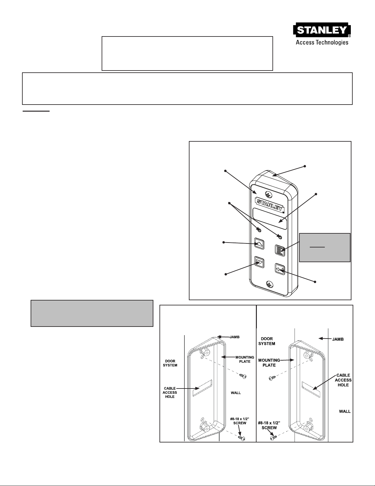
5.1 Remove the LCD Screen protector
5.2 Verify the door is being controlled by the ECO Pro
5.2.1 From the Home Screen, use Up/Down Arrow keys to change the operang mode of the
door from “Automac” to “Closed Locked.” Verify door goes to “Closed Locked.” Use
Up/Down Arrow keys to change operang mode back to “Automac.” Verify door returns
to “Automac” operaon.
5.3 Refer to Aachment 6 “Quick Start Manual.”
5.3.1 Remove Aachment 6 and review basic operaon of ECO Pro with the facility owner or
person overseeing the daily operaon of the door.
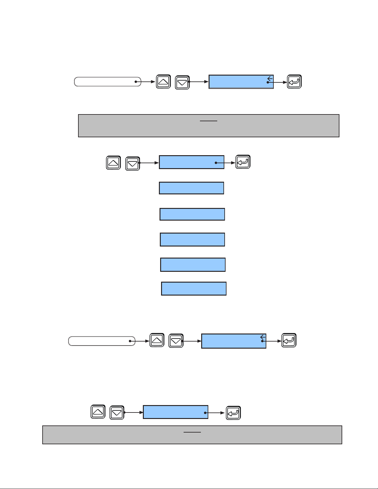
4.3.3 Set Trac Sense.
Enabling Trac Sense allows the ECO Pro to temporarily switch the operang mode from
Reduced to Automac (or Reduced Oneway to Oneway) during periods of high trac. When trac
returns to lower levels, the operang mode automacally returns to reduced. Trac Sense is
disabled by default and the Trac Sense Level is set to O by default.
• From the Funcon Menu, arrow to “Trac Sense” and press “Select.”
• Arrow to either “Enabled” or “Disabled” and press “Select” to save.
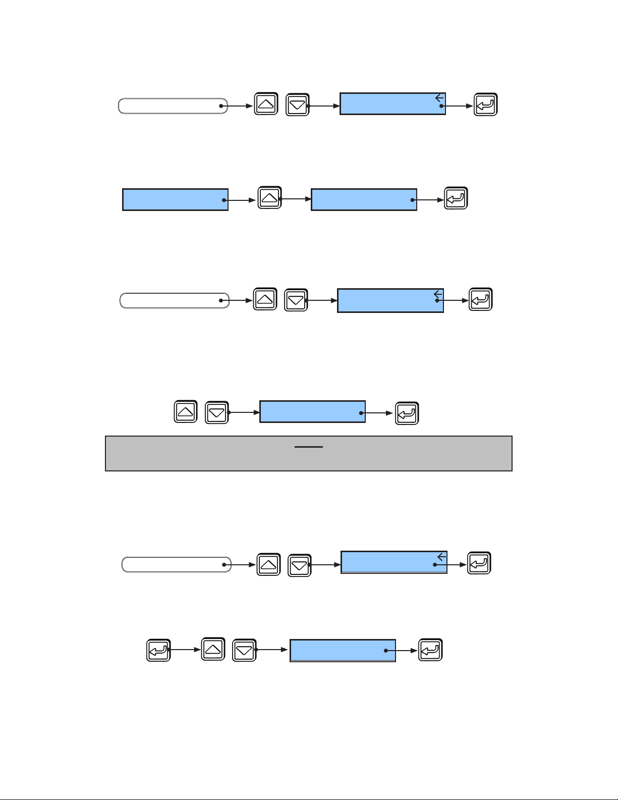
4.3.2 Set Hold Open Mode.
Hold Open Mode allows for ECO Pro to use two dierent methods of Hold Open. “Normal”
Hold Open Mode is the standard method of keeping the door open permanently. “Timed” Hold
Open Mode allows the user to select a med Hold Open selecon which keeps the door open for 15
minutes, 30 minutes, 45 minutes or permanently. Once the selected Hold Open me is expired, the
doors will return to previous operang mode. Hold Open Mode is set to “Normal” by default.
• Arrow to either “Normal” or “Timed” and press “Select” to save.
• From the Funcon Menu, arrow to “Hold Open Mode” and press “Select.”
PRESS PRESS SEE
OR
Trafc Sense:
Enabled
Trafc Sense:
Disabled
END
Hold Open Mode:
Normal
PRESS PRESS
SEE
OR
Hold Open Mode:
Timed
END
Note:
Trac Sense Level is adjusted in the main menu. The user must select a reduced
operang mode to ulize Trac Sense.
PRESS SEE PRESS
Hold Open Mode
FUNCTION MENU
START
PRESS PRESS SEE
Trafc Sense
FUNCTION MENU
START
204082
Rev B 10/11/2012
Page 7 of 12
© 2012, STANLEY BLACK & DECKER. ALL RIGHTS RESERVED.

Aachment 2. ECO Pro Machining Reference
ECO Pro Machining Instrucons
1. Locate the area where the ECO Pro is to mount.
2. Using a center punch, locate the center for the cable access hole and
the mounng holes for the screws.
3. Mark/punch the mounng screw locaons.
4. Cut a 1.250” hole using a hole saw.
5. Using a #26 drill bit (.147” dia), drill the 2 holes for the mounng
screws.
Note: This is a reference only drawing. Drawing is not to scale.
Aachment 1. ECO Pro Wiring Diagram
204082
Rev. B 10/11/2012
Page 8 of 12
© 2012, STANLEY BLACK & DECKER. ALL RIGHTS RESERVED.

Aachment 3. ECO Pro Checklists
ECO Pro Conguraon Checklist
Step Acon Reference
Secon Complete?
1Set Date and Time 2.7
2Enable ECO Pro 3.3
3Record Door ID 3.4
4Record Service Date and Erase Error
History 3.5
5Set MC521 Pro Start Up Mode (Opon)
Default Start Up Mode is “Automac” 3.6
6 Set Door Funcon Switch
Default Funcon Set is “3 Posion” 4.2
7 Set Closed Mode (Opon)
Default Closed Mode is “Normal” 4.3.1
8Set Hold Open Mode (Opon)
Default Hold Open Mode is “Normal” 4.3.2
9 Set Trac Sense (Opon)
Default Trac Sense is “O” 4.3.3
10 Perform ECO Pro Closeout Procedure 5
ECO Pro Service Checklist
Step Acon Reference
Secon Complete?
1Review Error History:
• From Main Menu, arrow to
“Access Diagnoscs Menu” and
press “Select”
• Arrow to “Display Door Error
History” and press “Select”
• Press “Menu” to return to Main
Menu
NA
2Service Door as Necessary NA
3Record Service Date and Erase Error
History 3.5
Aachment 4. Replacement Parts
Product Descripon Stanley Part Number
Harness, ECO Pro to Control Box, 180 inches 417161-1
Harness, ECO Pro to Control Box, 480 inches 417161-2
204082
Rev B 10/11/2012
Page 9 of 12
© 2012, STANLEY BLACK & DECKER. ALL RIGHTS RESERVED.

Aachment 5. Applicaons
1. Access Control – Full Control by ECO Pro
The ECO Pro / MC521 Pro system can be used with access control systems by connecng
the acvaon output of the access control system to the push plate input of the MC521
Pro (TB4-9 to TB4-10).
In this way the ECO Pro can automacally schedule the correct operang mode of the door
with full control.
2. Access Control – Access Control Override of ECO Pro
The ECO Pro / MC521 Pro system can be used with access control systems by connecng
the acvaon output of the access control system to the hold open input of the MC521
Pro (TB2-1 to TB2-2).
In this way the ECO Pro can automacally schedule the correct operang mode of the door
with full control.
3. “Morning Entry Switch”
The ECO Pro / MC521 Pro system can be used with a morning entry switch that permits
users to open the door even though the ECO Pro is set to keep the door in Closed mode.
This is accomplished by connecng a switch / key-switch to the hold open input of the
MC521 Pro (TB2-1 to TB2-2).
204082
Rev. B 10/11/2012
Page 10 of 12
© 2012, STANLEY BLACK & DECKER. ALL RIGHTS RESERVED.

Aachment 6. ECO Pro Quick Start Guide
Use UP or DOWN ARROW
keys to select desired
operang mode.
To correct alerts, press
SELECT and advance through
the suggested instrucons.
When complete, look for the
steady GREEN LIGHT and for
the LCD HOME SCREEN to
return to desired operang
mode.
A steady GREEN LIGHT
indicates the door is
funconing properly.
A ashing RED LIGHT
indicates the door is not
funconing properly.
The LCD HOME SCREEN
displays the operang mode,
alerts, instrucons to correct
alerts, and service contact
informaon as necessary.
Press MENU* to return
to previous screen. Use
MENU to access addional
capabilies and opons.
* MUST BE HELD FOR 2 SECONDS TO
ACTIVATE.
Installer, Separate from Installaon Manual. 204082
Rev B 10/11/2012
Page 11 of 12
© 2012, STANLEY BLACK & DECKER. ALL RIGHTS RESERVED.

This page le intenonally blank.
204082
Rev B 10/11/2012
Page 12 of 12
© 2012, STANLEY BLACK & DECKER. ALL RIGHTS RESERVED.
Table of contents
Other Stanley Switch manuals
Popular Switch manuals by other brands

Huawei
Huawei S5720I-SI Series quick start guide

Contemporary Controls
Contemporary Controls CTRLink EISC-100T installation guide

serva
serva BlueLine BlueSpin Cryo instruction manual

Black & Decker
Black & Decker Lights Out 90539953 instruction manual

HRT
HRT SW-DVI-2A user manual

Alba Fiber Systems
Alba Fiber Systems AFS6514 Installation and operation instructions

Cisco
Cisco Nexus 9000 Series Configuration guide

D-Link
D-Link DGS-1005D - Switch manual

NETGEAR
NETGEAR GSM4248PX Hardware installation guide

ADDER
ADDER View DVI AV4DVI Installation & use

Girard Systems
Girard Systems 98GC230 installation guide

Cooper
Cooper Crouse-Hinds WSQ Series Installation & maintenance information