Stanwax Laser S4i User manual

General Purpose ILDA interface board S4
Revision 4.06 June ‘16
Introduction
The Stanwax laser ILDA interface board is designed to make internal wiring of a laser projector a simple affair by taking the
ILDA signals and providing easy access to the connections. However its prime function is to provide safety interloc
k circuits
as required by the regulations. The safety interlocks include a key switch (or other interlock circuit), plus e-
stop and ILDA
cable interlocks plus output is provided for a laser emission LED to be located on the front of the projector. The remo
te
interlock connection also has the facility to connect a laser start button and a laser status LED that can be housed remotely
with the e
-
stop plus there is facility for many projectors equipped with this board (or any Stanwax ILDA board V1.03 onwards)
to be operated by a single e-
stop. All of these features are designed to assist in making the projector comply with BS
EN:60825-1:2007. Previous versions of this product have been used in USA to achieve projector variance.
What’s New?
This latest version of our best selling product is the most feature packed
yet. It has lots of new features but maintains the important interlock and
emergency stop features that we have come to expect.
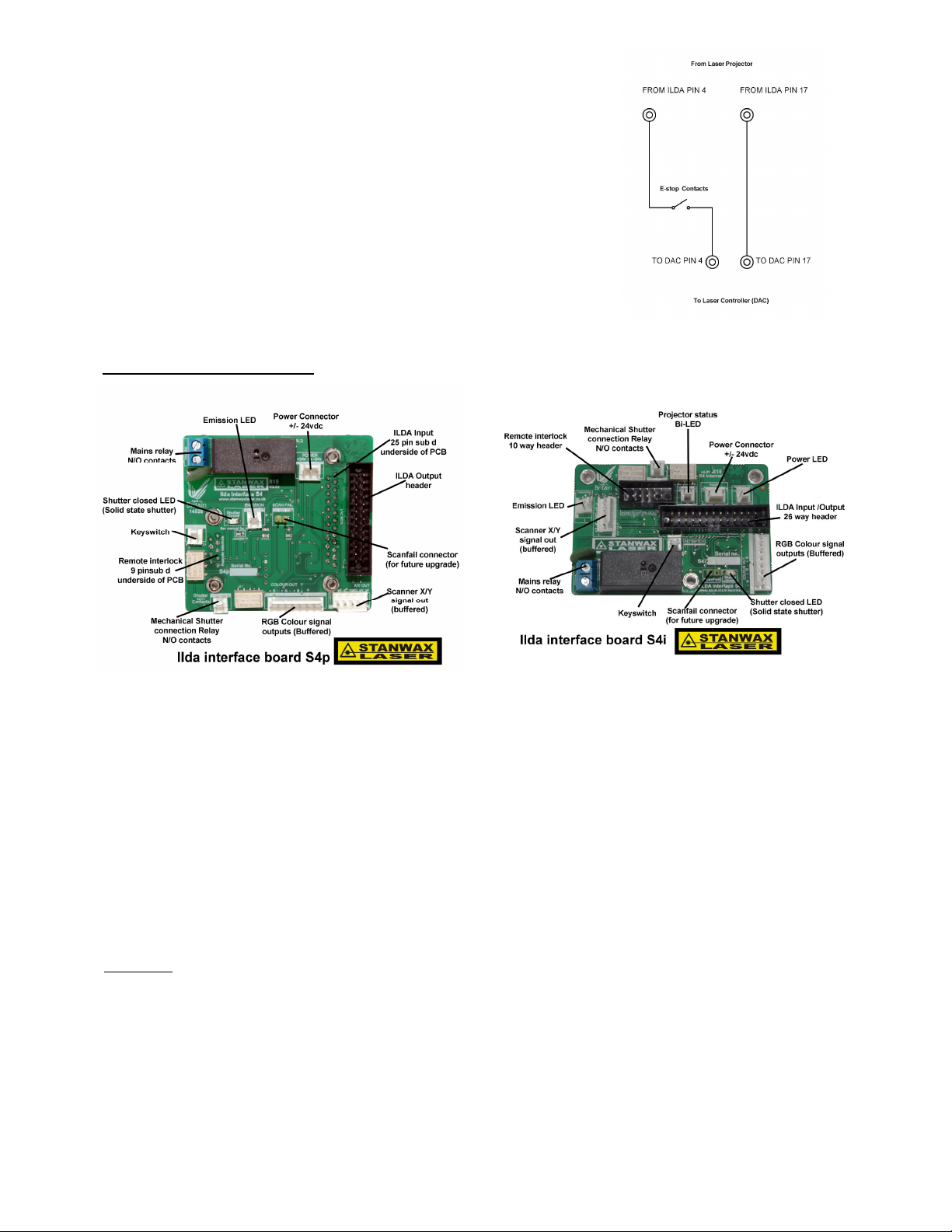
The first big change is that there are now three versions of the board.
This manual deals with the two shown right. The third version designed
for Pangolin Flashback
4 has its own manual (available from our
download page). As well as the traditional panel mount board (S4p right
in image), there is now an electronically identical dedicated internal
board, (S4i left in image). The panel mount board is 100% compatible
phy
sically to the old board (V1.xx) and has all the same electrical
connections so can easily be swapped out with a previous model. The
only addition to this is that Ildaboard S4 requires a split rail supply (see
connections later in this manual).
The new features are buffered signals for X/Y RGB inputs, a user programmable time delay (zero to 60 seconds), and a
relay to provide output to electro-mechanical shutters (giving wide compatibility).
The most significant feature however is the addition of *Stanwax Solid State Shutter technology –
hence the name S4. This
provides an electronic s
hutter that will kill laser output via the laser modulation lines in <100uS. This has been developed
and tested over a number of years so we are confident that you will have the safest laser projector yet with this system.
This feature has the added bonus of a connector for scan fail which is provided in readiness for future upgrades.
Despite all the changes, the interlock loop and reset circuit have been carried over from V1.xx so you can be certain of a
tried and tested emergency stop and interlock system.
Finally one further addition is an option on how the electro mechanical shutter is operated. This will be explained in detail
further on – (see section ‘Jumper P’)
*for full explanation see section marked ‘S4 technology’
Operation
The Ilda board has an on board timer chip that controls the relay that powers the lasers in the projector and the control
signal to the solid state & electro-mechanical shutters. This timer is held in a hard reset condition when the interlock loop is
broken or the emergency stop is tripped. The interlock circuit consists of a short circuit protected 12V feed which is routed
though the interlocks before reaching the timer chip and allowing it to come out of reset. Using the ILDA standard interlock
pins (4 & 17), the signal is passed through the ILDA lead to the laser control hardware and back. It then passes to the key
switch pins which as well as providing a connection for a key switch, and can provide connections to other interlocks, such
as a case open micro switch. (additional interlocks should be wired in series and set that they go open circuit when the
projector needs to be in a ‘safe condition’.) Following the key switch connector, the signal is presented to the remote
interlock connector. Externally this is a 9 pin sub-d connector on the projector rear panel. To ensure a fail safe system the
connector used externally for the remote connector must link out to complete the continuous loop, as any break in it will
prevent the laser from operating. The remote connector also provides connections for an emergency stop for use at the
laser control position, which must use contacts that close when the e-stop button is released. We recommend a ‘Key Only’
release for added security.
As the interlock loop and the E
-stop circuit must be complete for the system to operate, any break in either will result in the
laser output ceasing. This would include disconnection or breaking of the cables to the E-stop or the interlock circuit,
providing a fail safe system.
Once the interlock circuit is complete the timer chip comes out of reset as indicated by the Bi-colour LED turning green.
This signifies that the projector is armed and ready to be activated. Closing momentary contacts between pins 5 & 7 on the
9-way remote interlock connector will start a short time delay (this delay is factory set to 7 seconds but can be user set, for
up to 60 seconds - see ‘user programmable timer’ section). As the time is elapsing the Bi-
colour LED will flash red to green
indicating that the time sequence is in progress before remaining red indicating that the time delay is complete. At this
moment the solid state shutter is opened allowing the laser sources to output, and the emission LED is provided with
power and the relay will energise providing power to the laser sources.
Whenever the Bi-colour LED is lit static red, the laser is now fully active and laser emission is enabled. There are
connections on the 9-way remote interlock connector for this LED to be duplicated at a remote location, and an E-stop with
LED and start button can be used to provide all of the functionality you need at your control station.
Connecting up the ILDA Board
The connections on S4p are 100% compatible with previous models (V1.xx) with the only addition of a negative power supply
line.
Connections – refer to the images above & connection diagram at the end of the document
ILDA input – 25-way sub d male (on underside of PCB S4p only)
ILDA Input(/Output) – Header for connecting IDC 26 way lead to be used as ILDA output (un-buffered) on S4p (left) and as ILDA in/out on S4i (right)
Colour Blanking outputs – Provides buffered colour outputs for R,G,B, signals (8 way connector for back compatibility to V1.xx)
Remote Interlock – 9 pin sub d on S4p and 10 way box header on S4i
For connecting Emergency stop button plus optional Start Button and Bi-colour LED for laser status (see connection details next page.)
Key switch - connection for security key switch. This can also be used to connect other interlock loops such as a housing interlock switch.
Wire N/O contacts in series with key switch to facilitate this.
Emission LED – Any 2v LED can be used directly across these pins. The emission LED should not be a Bi-colour type and if used only one LED will light.
Scanner Out - Buffered X & Y axis scanner signals. Full differential outputs plus ground (centre pin – not normally needed)
Shutter output – N/O relay contacts for placing in series with the shutter and its power source. Not for mains power. See specifications for maximum power ratings.
Shutter Closed LED – Lights to indicate the status of the solid state shutter only. Lit = Shutter closed & laser output disabled.
Mains relay N/O contacts - Connect in line (series) with mains live feed to laser modules (includes an inrush current suppression device.)
Power – +/-24V DC power input. The board must be supplied from an ‘always on’ source as it switches power to the laser modules following a start-up time
delay. We would recommend using the scanner power supply as long as it has enough ‘spare’ current capability to power the board.
Scanfail - Not used at this time, for future upgrade. The connector must be left open, shorting the pins will cause the solid state shutter to close preventing laser output.
S4i Version only
Projector Status Bi-Led – Status indicator LED shows condition of the laser projector
(fitted to PCB on S4p) Out - interlock loop broken or e-stop tripped
Green – Interlock loops good and e-stop reset - laser ready for start
Flashing red/green every second – Laser start-up sequence initiated.
Red – Laser active and power applied to laser sources
Power LED – ILDA board has power
(fitted to PCB on S4p)
If you do not need a start f
unction (laser output is below class IV) then the start
button pins can be joined on the rear of the 9-
pin remote connector, and as soon as
the interlocks are all made the time delay will begin.
Should wish to implement a simple E-stop at your control station then the 9-
way
remote interlock connector can be fitted with a shorting link (see diagram under
section ‘service plug’).
This simplified e-stop is only suitable if using a single stop per projector, and uses
the ILDA interlock between pins 4 and 17. These connections can be ‘broken out’ at
your remote control station adjacent to the laser control hardware. In this instance it
is recommended that the E-stop and Laser hardware (such as Pangolin FB3) be
wired in series so that the interlock loop is bro
ken and laser power will be cut in the
event of the hardware becoming disconnected. (See wiring suggestion above right)
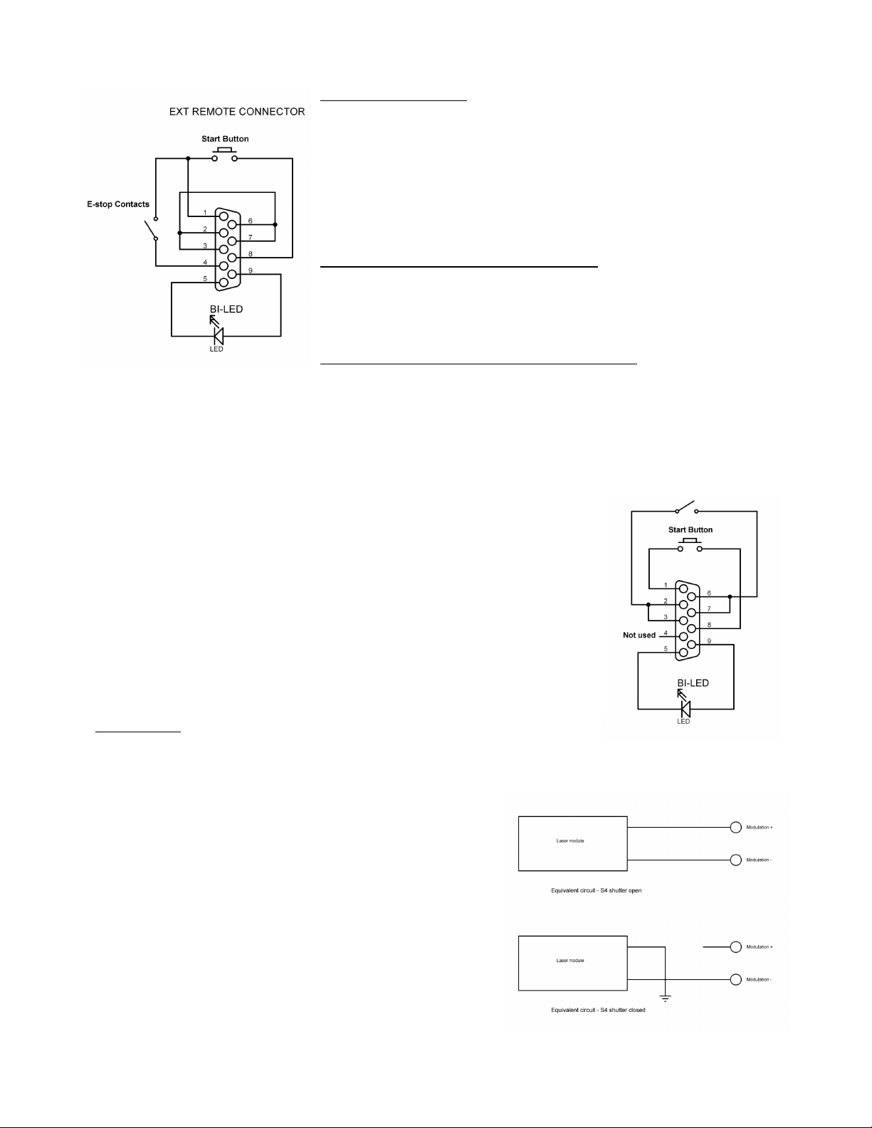
Remote Interlock connector
Connections for the remote interlock are shown right (as viewed looking at the
connector on the rear panel.
Note if you have used earlier versions of the ILDA board, pin 4 is now in use as the
multiple e-stop connection. (see section below titled ‘Using a single E-stop’)
It is advised for future compatibility to use this arrangement with pin 4 as an E-
stop
connection as shown left.
The Bi-
LED should be wired up so that the Red LED is on when the laser is active
and the Green LED is on when the laser is armed before the start button is pressed.
Note pins the projector interlock connections 2 & 3 are joined on the PCB as are 6 &
7 so in practice only one pin from each row need to be joined to complete the loop.
Remote Interlock Pin Assignments (9 pin connector)
1 – Ground 6 - Projector Interlock B
2 - Projector Interlock A 7 - Projector Interlock B
3 - Projector Interlock A 8 - Start button
4 - E-stop control pin 9 - Bi-Led
5 - Bi-Led Flat
Remote Interlock Pin Assignments (10 way box header S4i)
1 – Ground 2 - Projector Interlock B
3 - Projector Interlock A 4 - Projector Interlock B
5 - Projector Interlock A 6 - Start button
7 - E-stop control pin 8 - Bi-Led
9 - Bi-Led Flat 10 – not used
Note these pin assignments are provided for completeness
If using the optional lead the pin assignments for the 9 pin connector will be sufficient
If using an E-stop that’s compatible with and older V1.01 or V1.02 ILDA Board then you need
to mod the wiring to include grounding of Pin 4. Either method shown will work as a suitable
E-stop connection though we would advise using the diagram above as all future boards will
use this method. The projector will not work unless pin 4 is grounded AND the projector
interlock A and B pins are shorted together.
The board is provided in one of two variants, the S4p variant has two sub d connectors on the
rear of the PCB and is designed for panel mounting on the rear of the projector. In this case
you will need to mount it using a Stanwax Laser mounting panel or drill and cut your own rear
panel according to fig1 on the diagram at the end of this document.
The S4i variant allows the user to mount the PCB inside the projector (not protruding through
the rear panel). Instead of the 9-pin Sub D there is a 10 way box header on the board
providing connections for the remote interlock.
S4 Technology
Stanwax Solid State Shutter technology uses high speed electronic
switches to route the modulation signals to enable or disable the laser
output as dictated by the system.
In normal operation, the ILDA modulation signal (after passing through the
on board signal buffer) is routed by the solid state shutter to the laser
modulation line, so the laser will operate as dictated by this signal.
When the solid state shutter closes, it will change the routing of the
modulation signal, by disconnecting the laser modulation input from the
signal buffer output. At the same time it will connect the laser modulation
lines (+ & -) together and short them to ground preventing any output.
The system uses switches as opposed to opto-isolators (which can leave
the modulation lines floating) to ensure a low loss of signal as well as high
speed operation.
The S4 switches will extinguish the laser beam in <100uS.
See the diagram (right) which shows the electrical equivalent circuits when
the S4 shutter is open and closed.
The S4 shutter operates independently of the electro mechanical shutter
output which on this version of the board is provided by a set of relay
contacts, though they are both controlled by a combination of the ILDA
shutter signal and the status of the output of the e-stop, interlock loop &
timer outputs. The electro mechanical shutter has two operating modes
which are described below (see Jumper ‘P’ section), and do not affect the
performance or operation of the S4 Shutter.
With the power relay, S4 shutter and electro mechanical shutter this board
provides three means to stop the laser output.

The User Programmable Timer
New for ILDA Board S4 is the ability for the user to program the timer, the delay of which can be set between 0 and 60 seconds
in 1 second increments. Setting the timer is very simple but will require the user to connect a suitable control to the remote
interlock connector. This can be a Stanwax Emergency stop or an equivalently wired device. The bi-coloured LED provides
status information so this must be connected if its not fitted to the projector, in addition to a start button.
All references to ‘the LED’ in the following section are in reference to the bi-coloured LED
IMPORTANT.
To avoid the system accidentally entering program mode we have designed the firmware to overlook certain conditions. For
example, if using a service plug on the remote connection (see ‘Service Plug’ later in this manual) the pins for the start button
will be shorted. In this case the projector will start and function as normal without program mode becoming active. Additionally if
there is an ILDA shutter signal present while holding down the start button, the system will NOT enter program mode so if you
are setting the timer you must ensure that there is no laser output enabled in software when you want to use program mode.
Programming
To enter program mode, power up the projector and press and hold the start button. The LED will flash red and green, and
following the delay the relay will click and the emission LED will light as normal. Keep the button held down and release it as
soon the relay drops out and the emission LED goes out (aprox. 2 seconds).
If the button is not released now the board will exit program mode and the relay will pull back in.
The board is now in program mode indicated by the LED which will begin to flash rapidly from red to green after a few seconds.
Once program mode is entered the timer value is set to zero and the NVRAM is cleared, therefore if you wish to have a zero
start delay, you can reset* the projector at this point. Following this whenever you press the start button the laser will come on
immediately without a delay.
Set to factory default
In program mode press and hold the start button (as soon as the button is pressed the LED will light green) and continue to hold
until the LED begins to flash green (aprox 2 seconds). Once the LED is flashing green, reset* the projector and the factory
default of 7 seconds will be set and stored in NVRAM.
Set your own start delay
In program mode briefly press then release the start button, the LED will go green for aprox. 3 seconds. After this time it will
begin to flash from red to green. Count the red flashes. The LED flashes red to green every second so if you count 10 red
flashes this will equate to 10 seconds delay. Once the number you require has been reached press the start button again and
hold it pressed until the LED goes steady green. As you release the start button the LED begins to flash red only indicating that
programming is complete and the new delay value is stored in NVRAM** If the start button is not pressed during this procedure
the system will stop when it reaches the maximum time of 60 seconds. This will be indicated by the LED flashing red.
The custom time delay is now set and the projector can be reset* or can be restarted by briefly pressing the start button twice.
The first press will reset the board and leave the LED set to green, the second press will run the start timer with the new time
delay set and start the projector.
*when we refer to reset of the projector this can be achieved by a power cycle or by breaking the interlock loop, the easiest way
is by pressing the e-stop.
**if the board is reset by breaking any part of the interlock loop or by loss of power while its recording, then the delay will be set
to zero. The only alternative to this is if the max time of 60 seconds is reached as described above.
Programming multiple projectors
If a number of projectors are linked to a single e-stop as shown in the section ‘Using a single e-stop’ then programming of the
timer can be made to all the projectors together, ensuring they all have the same setting.
Modifying ILDA Board 1.03
If you have some projectors already equipped with ILDA board 1.03 and you would like this feature we can modify the board for
you for a small fee or provide you with a programmed microcontroller to fit yourself.
Please email us at sales@stanwaxlaser.co.uk
Jumper P
New for Ildaboard S4 is a solder jumper on the PCB we call Jumper P (see image nest page to identify its position). Its setting
will affect the function of the electro mechanical shutter output via the on board relay, but not the solid state shutter acting on the
laser modulation lines.
The reason for Jumper P
Laser frames and shows can close the shutter when there is no output to the lasers. If this occurs during a ‘dead’ section of the
cue or show and occurs frequently for short durations it can cause an electro mechanical shutter to clatter in and out creating
interference, noise and unnecessary wear and tear to the shutter. This was appropriate in the days of gas and ion lasers but is
not needed with modern directly modulated lasers.
When pads 1 & 2 are joined then the system will monitor the ILDA shutter signal and as the ILDA shutter signal goes high to
open the shutter the relay will be activated in the normal way. However when the ILDA shutter signal goes low a slight delay is
added to the control of the shutter relay. Therefore if the shutter signal is changing state rapidly the shutter will not follow. It will

always open immediately with the shutter signal but will only close once the shutter signal disappears and the short delay has
elapsed.
This function is overridden by an emergency stop operation, therefore ensuring 100% safe operation.
With pads 2 & 3 joined the shutter will open and close to follow the ILDA shutter signal. (factory default setting)
If you don’t use a shutter and prefer the relay not to be activate leave all 3 pads of Jumper P unsoldered.
See a video of this feature in action on our Youtube channel – search StanwaxLaser
Using a single E-stop
A popular feature carried over from V1.03 is the ability to connect many projectors equipped with these boards together to work
from a single e-stop and start button. Irrespective of whether you are using a single projector or multiple projectors, it is
recommend to wire the e-stop as per the diagram marked ‘Ext Remote Connection’ to ensure forward compatibility.
When multiple projectors are used, the 9 pin remote connector of the first projector in the ‘chain’ will provide e-stop and laser
status LED signals to the emergency stop control, as well as the start button function. The other projectors need only have 3
pins from the 9 pin connector wired to each other as shown in the diagram below. In effect there are now two interlocks present
on the remote interlock connector, and it is important that both are used. The reason that there are two is so that each projector
can keep its own interlock loop (via its key switch and ILDA input) and this will then affect just one projector, if its own loop is
broken. For example if one ILDA input lead had not been secured properly and slipped out, then just that one projector would be
affected rather than killing the output to all projectors in the e-stop chain.
As you can see the connector for projector 1 has the e
-stop and start button contacts as well as the laser status Bi-Coloured
LED connected to it, the others need only have pins 1, 4 and 8 from the 9 pin connector joined. Also note that connecting via
the interlock loops the e-stop function is independent of the ILDA inputs so it does not matter if the projectors are running of
one laser controller or several, the e-stop and start function will still work.
Using XLR leads for e-stop
As the stop system here uses just 3 pins we recommend connecting the projectors and the
e-stop using industry standard XLR leads. This makes hook-up relatively cheap and often
the run from stage to FOH can be done using a spare in house patch. We have used this
system extensively for a number of years so can verify that it is robust.
The system we employ on our own projectors, uses adaptors that connect to the 9 pin Sub-d
remote interlock connection, and we have one lead with a 5 pin xlr that runs to the e-stop but
use 3 pin links between the projectors. If you don’t wish to have the Bi-coloured Status LED
on your stop then you can use 3 pin leads throughout, including 3 pin male and female
sockets on the projector if you have the space on the rear panel.
We recommend having a female on the e-stop (we supply modified e-stops already wired
with 5 pin XLR connections) so that the male XLR is always facing
towards the e-stop. If you
employ this and the wiring standard shown right then connecting with other projectors owned
by other people and employing this system will always be a possibility.
XLR Pin Assignments
1 – Ground
2 – Stop
3 – Start
Optional connections to E-stop only
4 – Bi-LED
5 – Bi-LED (flat)

Mounting the board
To mount an S4i board inside the projector, use Fig 2 to mark and drill mounting holes. With this version the power LED and Bi-
colour laser status LEDs can be connected to the on board headers & mounted on an external panel of your projector. See
‘connection details’ & the wiring diagram for how connect these LEDS. The fitting of the LEDs is optional.
It is recommended that if mounting to a metal panel within the projector, the panel should be insulated below the mains part of
the PCB. Alternatively, the board could be mounted on a plastic or fibreglass insulated mounting panel.
Relay contacts should be wired in series with the live feed to your laser power supply feed, a protection device on the board
reduces the chance of relay contact failure or fuse blowing from current inrush when using a switch mode power supply. If used
with a Stanwax Laser Power Distribution Board then the two connections on the ILDA board should be connected to the ILDA
Board connections on the Power Distribution PCB. It does not matter which way round this pair of wires is connected
WARNING. This device is designed to switch live mains. Wiring to this device should be performed by a competent
person trained in electrical wiring to ensure your equipment is safe. Electricity can kill! If you have any doubt about the
safety of the equipment after wiring it should be checked and certified by an electrician before use.
Wiring the ILDA board to a DMX projector
If you have a DMX equipped projector, use the diagram right as a guide
to how the ILDA board can be wired to maintain the DMX function.
DMX lasers differ in their wiring so this can only be used as an
example. Many such projectors will use the ILDA interlock pins to
sense if there is ILDA input, and therefore switch from internal to
external control. You will therefore need to do this manually with a
switch on the projector. Connect the switch to the DMX board pins that
would normall
y connect to the ILDA input pins 4 and 17. Set it so that
when made the ILDA input is ignored and the DMX board is activated.
The ILDA board will need to have pins 4 and 17 correctly shorted to
complete the interlock loop so connecting this to the same switch as
the DMX board 4 & 17 wires is a good idea.
The input to the DMX board for scanner and blanking as shown can be
made to where the ILDA input would normally connect.
An e
-stop connected to the remote interlock connection will then
operate as normal. If daisy chaining then several DMX projectors could
work along side projectors operating from an ILDA signal and the E
-
stop function will work on all projectors
Service Plug
If you wish to make a service plug to automatically start the projector for bench
testing purposes you can wire a 9pin DB 9 connector as shown in the diagram.
Alternatively we can supply such a plug complete with a Bi
-colour LED for a
small charge.
Please contact us for details using sales@stanwaxlaser.co.uk

Troubleshooting
The Stanwax Laser ILDA interface board has proved very reliable in laser projectors all over the world but occasionally problems may occur.
Below is listed a few basic things to look for if the board will not work. If you struggle to get the board to function please contact us and we will
help to get you going.
Power LED lights but Bi-colour LED is out
This indicates that the projector interlock loop is open or the E-stop control pin is not grounded. Both of these conditions must be met or the LED
will not light.
Bi-colour LED lights green but the projector will not output
The Bi-LED lighting green shows the projector is ‘ready’ to start, and will npot start until the start button is used. The start button should be a
momentary push to make spst switch and must be connected between pins 1 & 8 of the remote interlock connector
The Bi-colour LED lights red but the lasers a have no power
The relay may not be pulled in, the board needs a +/-24V power supply and the relay is a 24V type (though other voltages are available to
special order). If the power supply is low the relay may not have enough voltage to pull in despite the rest of the board appearing to function
correctly
The emission LED will not light
The connection for this LED is marked for polarity, ensure that it is wired the right way round. Any standard 2-3V LED will function on this
connection and no series resistor is required.
Scanner output has a ‘wobble’
Normally the board should be powered by the scanner PSU, though any ‘always on with the projector’ supply of suitable rating will work. If using
an auxiliary supply (not the scanner PSU) then you may need to ground this supply to the scanner PSU. This can be done using the centre pin
of the 5 pin X & Y signal connector which normally need not be connected.
Specification
Dimensions – S4p 69mm x 65mm x 25mm (depth from panel when panel mounted)
– S4i 74mm x 50 mm x25mm
Power – +/-24V DC provided from an always on source.
Current – 80mA relay inactive
– 100mA relay active
Shutter Contacts – 24VDC 3A max. If the shutter is an inductive load (such as a solenoid type) a clamping diode must be
connected in reverse across the shutter coil close to the shutter, otherwise the relay contacts may fail.
Start up delay – 7seconds (factory default) or user programmable 0-60 seconds
Switching Current – 5A @250VAC Max Note relay contacts are rated for 12A but inrush protection limits total to 5A
Interlock Voltage – 12V with series resistor for short circuit protection
Solid state shutter - <100uS to laser extinguish (dependant on modulation speed of laser driver)
reaction time

Wiring diagrams –
a diagram showing full wiring of a projector using our products can be downlaoded from our website
Note. The centre pin on the 5 pin connector for scanner output is a ground pin and is connected to ILDA pin 25. This pin is only
needed to ensure the scanner drivers and the ILDA board power supplies have good ground connection between them. If you
are using the scanner power supply to power this board then this pin does not need to be connected.

©2016 Stanwax Laser
This manual suits for next models
1
Table of contents
Other Stanwax Laser Computer Hardware manuals


