Stanwax Laser S4FB User manual

ILDA interface board S4FB
Revision 4.03FB June‘16
Introduction
The Stanwax Laser ILDA interface S4FB is designed to provide interl
ock and emergency stop functionality to a laser projector
fitted with Pangolins FB4 laser controller or to an FB4 fitted to a remote housing.The board contains safety interlock circuits,
that along with the ILDA shutter signal and emergency stop input, ena
ble or disable the laser output. The safety interlocks
include a key switch (or other interlock circuit), plus e-
stop and ILDA cable interlocks plus output is provided for a laser
emission LED to be located on the front of the projector. The remote interlo
ck connection also has the facility to connect a
laser start button and a laser status LED that can be housed remotely with the e-
stop plus there is facility for many projectors
equipped with this board (or any Stanwax ILDA board V1.03 onwards) to be operated by a single e-
stop. All of these features
are designed to assist in making the projector comply with BS EN:60825-
1:2007. Previous versions of this product have been
used in USA to achieve projector variance.
What’s New?
The latest development of our ILDA board uses an
electron
ic shutter to kill the laser output. Three
versions are available in total, This manual is for
S4FB for use with a Pangolin FB4. The S4i and S4p
versions are dealt with in a separate manual.
The S4FB version has been designed to neatly piggy
back on the re
ar of the FB4 as shown right. Power
fed to the ILDA board is passed on to the FB4 and
the colour signals from FB4 are fed to the ILDA board
where they pass through the solid state shutter which
is controlled by the e-
stop and interlock circuits as
well as
the shutter signal from the FB4. Unlike the
other versions S4i & S4p the scanner signals are not
handled by this board but should be used directly
from the FB4.
The most significant feature on the S4 version of our widely used ILDA board is the addition of *
Stanwax Solid State Shutter
technology – hence the name S4. This provides a six channel electronic shutter that will kill laser output via the las
er
modulation lines in <100uS. This has been developed and tested over a number of years so we are confident that you will
have the safest and most compliant laser projector yet with this system.
Despite all the changes, the interlock loop and reset circu
it have been carried over from V1.xx so you can be certain of a
tried and tested emergency stop and interlock system. Additionally as with all S4 versions, a user programmable time delay
for projector start up (zero to 60 seconds) can be implemented.
* see section ‘S4 Technology’ for full explanation
Operation
The Ilda board has an on board timer chip that controls the solid state shutter to the lasers in the projector. This timer is held
in a hard reset condition when the interlock loop is broken or the emergency stop is tripped, thus preventing laser output.
The interlock circuit consists of a short circuit protected 12V feed which is routed, initially, through the key switch pins. As
well as providing a connection for a key switch, this port can provide connections to other interlocks, such as a case op
en
micro switch. (additional interlocks should be wired in series and set that they go open circuit when the projector needs to be
in a ‘safe condition’.) Following the key switch connector, the signal is presented to the remote interlock box header. This is
used with a short ribbon cable to present a 9 pin sub-d connector on the laser rear panel. To ensure a fail safe system the
connector used externally for the remote connector must link out to complete the continuous loop, as any break in it will
prevent the laser from operating.
The remote connector also provides connections for an emergency stop for use at the
laser control position, which must use contacts that close when the e-stop button is released. We recommend a ‘Key Only’
release for added security.
As the interlock loop and the E
-stop circuit must be complete for the system to operate, any break in either will result in the
laser output ceasing. This would include disconnection or breaking of the cables to the E-stop or the interlock circuit,
providing a fail safe system.
Once the interlock circuit is complete the timer chip comes out of reset as indicated by the Bi-colour LED turning green. This
signifies that the projector is armed and ready to be activated. Closing momentary contacts between pins 5 & 7 on the 9-way
remote interlock connector will start a short time delay (this delay is factory set to 7 seconds but can be user set, for up to 60
seconds - see ‘user programmable timer’ section). As the time is elapsing the Bi-colour LED will flash red to green indicating
that the time sequence is in progress, before remaining red indicating that the time delay is complete. At this moment the
solid state shutter is opened allowing the laser sources to output, and the emission LED is provided with power.
Whenever the Bi-colour LED is lit static red, the laser is now fully active and laser emission is enabled. There are
connections on the 9-way remote interlock connector for this LED to be duplicated at a remote location, and an E-stop with
LED and start button can be used to provide all of the functionality you need at your control station.
If you do not need a start function (laser output is below class IV) then the start button pins can be joined on the rear of the
9-pin remote connector, and as soon as the interlocks are all made the time delay will begin.

Fitting the board
The board is provided with all the hardware needed to fit it to an FB4, and fitting should take just a few mins.
The board is now ready to be connected up following the diagram and key on the next page.
Remove the 4 screws and washers that hold the FB4
PCB to the standoffs on the unit. (see image right)
Take care not to shift the PCB as it will not be
mechanically supported during the next operation, and
could dislodge the flexible PCB for the OLED display.
Fit the 8 way connector from the ILDA board to the
header and push the red and black power wires into the
receptacles on the FB4 ensuring correct polarity.
Press the red and black wires firmly into the receptacle to
ensure a good connection.
Finally, carefully swing the board into position and using
the supplied screws fix the ILDA board to the standoffs on
the FB4 using a 2.5mm allen key.
Start all the screws before tightening any of them.
Tighten the screws firmly but don’t go crazy!
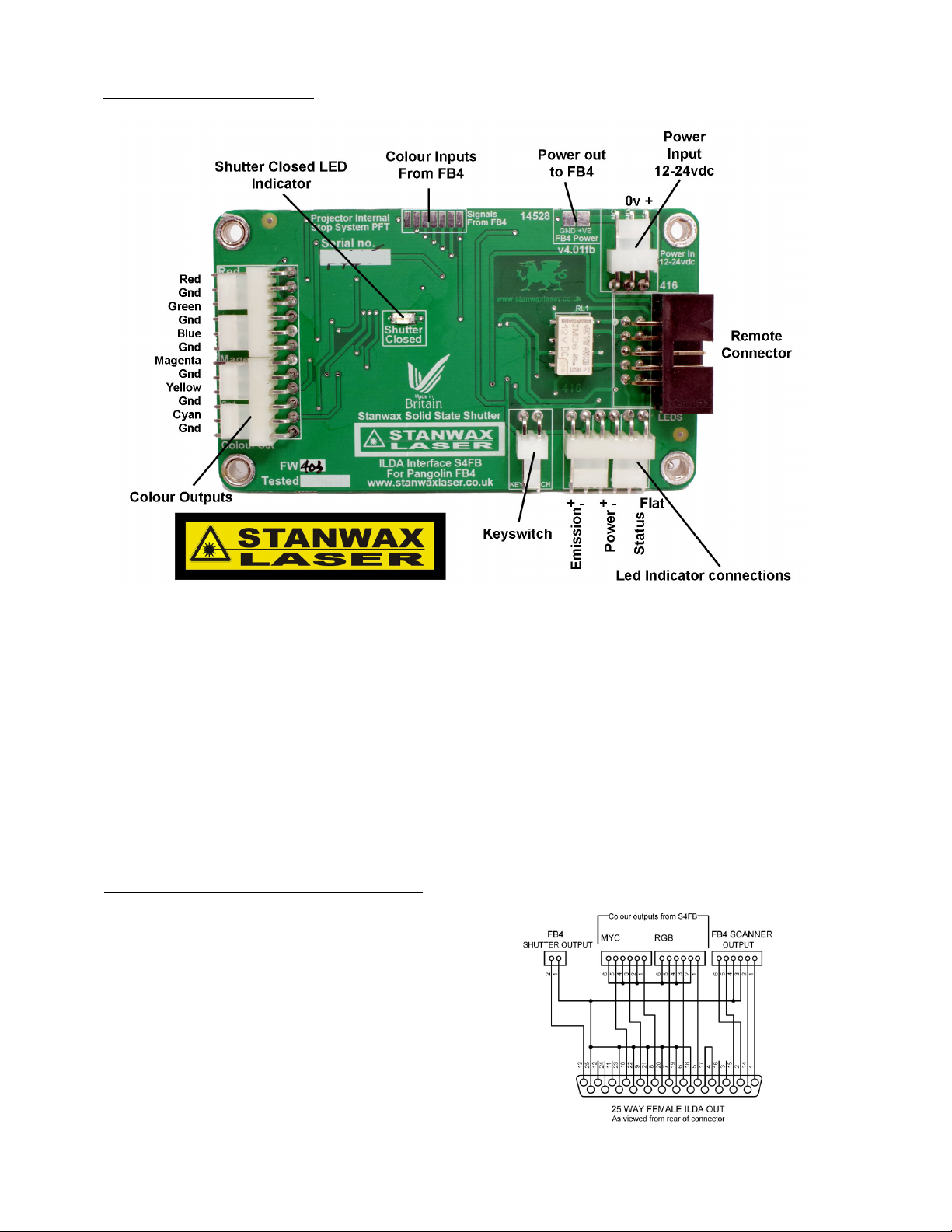
Connecting up the ILDA Board
Power connection –
12-24VDC (note the connector has an unused pin and is provided wit
h 3 pins to be 100% compatible with other versions of
this product) Looking from the top Right Pin +Ve Centre pin 0v Left pin NC
Colour outputs –
Outputs provided for R,G,B,M,Y,C with a ground pin provided on each channel for convenience.
Key switch -
Connect to key switch or other interlock switch such as a case open switch that will open when the laser needs to be in a ‘safe’
condition. We recommend a key switch that will not allow key withdrawal when in the set position. All circuits to be made in series with pins.
LED connections –
Outputs for Emission, Power and Status LED indicators. Right hand connection of each pair of pins should go to the LED pin
marked with a flat on the housing. Any standard 2v LED will be suitable for power or emission positions and no series resistor is required.
Remote connector –
10 way box header to connect to the ribbon cable to external interlock and E-stop connection that should be mounted on
the rear panel of the projector (for details of connections see the next section)
Power out to FB4 –
use the wires provided (not shown) to feed power to the FB4
Colour Inputs from FB4 –
Colour signal lines (using connector provided but not shown)
Using The S4FB with an FB4 in a remote housing
If your FB4 is to be used in a remote housing rather than being
fitted to a laser projector, then the S4FB board will operate just the
same for ILDA output from the FB4. It will not work on the pass
through output.
To wire the ILDA out connector use the shutter, & scanner signals
directly from the FB4 mini headers and take the colour modulation
lines from the colour output connectors on the S4FB. Pins 4 and
17 on the ILDA out connector should be joined together to
complete the interlock look as required by the ILDA standard.
See wiring diagram (right).
The S4FB remote interlock connector can be positioned on the
housing adjacent to the ILDA out connector.

The User Programmable Timer
New for ILDA Board S4 is the ability for the user to program the timer, the delay of which can be set between zero and 60
seconds in 1 second increments. Setting the timer is very simple but will require the user to connect a suitable control to the
remote interlock connector. This can be a Stanwax Emergency stop or an equivalently wired device. The bi-coloured LED
provides status information so this must be connected as well as a start button, if its not fitted to the projector.
All references to ‘the LED’ in the following section are in reference to the bi-coloured LED, unless stated.
IMPORTANT.
To avoid the system accidentally entering program mode we have designed the firmware to overlook certain conditions. For
example, if using a service plug on the remote connection (see ‘Service Plug’ later in this manual) the pins for the start button
will be shorted. In this case the projector will start and function as normal without program mode becoming active. Additionally if
there is an ILDA shutter signal present while holding down the start button, the system will NOT enter program mode so if you
are setting the timer you must ensure that there is no laser output enabled in software when you want to use program mode.
V1.03 onwards
Remote Interlock connector
Connections for the remote interlock are shown right (as viewed looking at the
connector on the rear panel.)
Note if you have used earlier versions of the ILDA board pin 4 is now in use as the
multiple e-stop connection. (see section below titled ‘Using a single E-stop’)
It is advised for future compatibility to use this arrangement with pin 4 as an E-
stop
connection as shown left.
The Bi-
LED should be wired up so that the Red LED is on when the laser is active
and the Green LED is on when the laser is armed before the start button is pressed.
Note: the projector interlock connections 2 & 3 are joined on the PCB as are 6 & 7 so
in practice only one pin from each row need to be joined to complete the loop.
Remote Interlock Pin Assignments (9 pin connector)
1 – Ground 6 - Projector Interlock B
2 - Projector Interlock A 7 - Projector Interlock B
3 - Projector Interlock A 8 - Start button
4 - E-stop control pin 9 - Bi-Led
5 - Bi-Led Flat
If using an E-stop that’s compatible with and older V1.01 or V1.02 ILDA Board then you need
to mod the wiring as shown right to include grounding of Pin 4. Either method shown will work
as a suitable E-stop connection though we would advise using the diagram from the previous
page as all future boards will use this method. The projector will not work unless pin 4 is
grounded AND the projector interlock A and B pins are shorted together.
S4 Technology
Stanwax Solid State Shutter technology uses high speed electronic
switches to route the modulation signals to enable or disable the laser
output as dictated by the system.
In normal operation, the ILDA modulation signal from the FB4 is
routed by the solid state shutter to the laser modulation line, so the
laser will operate as dictated by this signal.
When the solid state shutter closes, it will change the routing of the
modulation signal, by disconnecting the laser modulation input from
the FB4 output. At the same time it will connect the laser modulation
lines (+ & -) together and short them to ground preventing any output.
The system uses switches as opposed to opto-isolators (which can
leave the modulation lines floating) to ensure a low loss of signal as
well as high speed operation.
The S4 switches will extinguish the laser beam in <100uS.
See the diagram (right) which shows the electrical equivalent circuits
when the S4 shutter is open and closed.
The S4 shutter operates independently of the electro mechanical
shutter output which on this version of the board is provided directly
from the FB4.

Programming
To enter program mode, power up the projector and press and hold the start button. The LED will flash red and green while the
delay proceeds. Once the delay has elapsed, the emission LED will light as normal. Keep the button held down and release it as
soon the emission LED goes out (aprox. 2 seconds).
If the button is not released now the board will exit program mode and emission LED will re-light enabling laser output.
The board is now in program mode indicated by the LED which will begin to flash rapidly from red to green after a few seconds.
As soon as program mode is entered the timer value is set to zero and the NVRAM is cleared, therefore if you wish to have a
zero start delay, you can reset* the projector at this point. Following this whenever you press the start button, laser output will
become enabled immediately without a delay.
Set to factory default
In program mode press and hold the start button (as soon as the button is pressed the LED will light green) and continue to hold
until the LED begins to flash green (aprox 2 seconds). Once the LED is flashing green, reset* the projector and the factory
default of 7 seconds will be set and stored in NVRAM.
Set your own start delay
In program mode briefly press then release the start button, the LED will go green for aprox. 3 seconds. After this time it will
begin to flash from red to green. Count the red flashes. The LED flashes red to green every second so if you count 10 red
flashes this will equate to 10 seconds delay. Once the number you require has been reached press the start button again and
hold it pressed until the LED goes steady green. As you release the start button the LED begins to flash red only indicating that
programming is complete and the new delay value is stored in NVRAM** If the start button is not pressed during this procedure
the system will stop when it reaches the maximum time of 60 seconds. This will be indicated by the LED flashing red.
The custom time delay is now set and the projector can be reset* or can be restarted by briefly pressing the start button twice.
The first press will reset the board and leave the LED set to green, the second press will run the start timer with the new time
delay set and start the projector.
*when we refer to reset of the projector this can be achieved by a power cycle or by breaking the interlock loop, the easiest way
is by pressing the e-stop.
**if the board is reset by breaking any part of the interlock loop or by loss of power while its recording, then the delay will be set
to zero. The only alternative to this is if the max time of 60 seconds is reached as described above.
Programming multiple projectors
If a number of projectors are linked to a single e-stop as shown in the section ‘Using a single e-stop’ then programming of the
timer can be made to all the projectors together, ensuring they all have the same setting.
Modifying ILDA Board 1.03
If you have some projectors already equipped with ILDA board 1.03 and you would like the programmable timer feature we can
modify the board for you for a small fee or provide you with a programmed microcontroller to fit yourself.
Please email us at sales@stanwaxlaser.co.uk
Using a single E-stop
A popular feature carried over from V1.03 is the ability to connect many projectors equipped with these boards together to work
from a single e-stop and start button. Irrespective of whether you are using a single projector or multiple projectors, it is
recommend to wire the e-stop as per the diagram marked ‘Ext remote connector V1.03 onwards’ (on page 3 of the manual) to
ensure forward compatibility.
When multiple projectors are used, the 9 pin connector of the first projector in the ‘chain’ will provide e-stop and laser status
LED signals to the emergency stop control, as well as the start button function. This will require 5 conductors to connect to the
stop control, the other projectors need only have 3 pins from the 9 pin connector wired to each other as shown in the diagram
below. In effect there are now two interlocks present on the remote interlock connector, and it is important that both are used.
The reason that there are two is so that each projector can keep its own interlock loop (via its key switch and remote connector)
and this will then affect just that projector, if its own loop is broken. For example if one ILDA input lead had not been secured (or
interlock connection in the case of this board) properly and slipped out, then just that one projector would be affected rather than
killing the output to all in the chain.
Troubleshooting
The Stanwax Laser ILDA interface board has proved very reliable in laser projectors all over the world but occasionally problems may occur.
Below is listed a few basic things to look for if the board will not work.
Power LED lights but Bi-colour LED is out
This indicates that the projector interlock loop is open or the E-stop control pin is not grounded. Both of these conditions must be met or the LED
will not light.
Bi-colour LED lights green but the projector will not output
The Bi-LED lighting green shows the projector is ‘ready’ to start, this function must be provided. The start button should be a momentary push to
make spst switch and must be connected between pins 1 & 8 of the remote interlock connector
The Bi-colour LED lights red but the lasers are not outputting
Check that the ‘Shutter closed’ LED on the PCB is not lit. I flit it indicates that the Solid State Shutter is closed and the lasers will be
disconnected from the modulation signals. Ensure laser output is enabled in the software.
The emission LED will not light
The connection for this LED is marked for polarity, ensure that it is wired the right way round. Any standard 2-3V LED will function on this
connection and no series resistor is required.
Specification
Dimensions – 85mm x 50mm (the board add 15mm depth to the back of the FB4)
Power – 12-24V DC
Current – 40mA
Start up delay – 7seconds (factory default) or user programmable 0-60 seconds
Interlock Voltage – 12V with series resistor for short circuit protection
Solid state shutter - <100uS to laser extinguish (dependant on modulation speed of laser driver)
reaction time
© 2016 Stanwax Laser
As you can see the connector for
projector 1 has the e-stop and start button contacts as well as the laser status Bi-Coloured
LED connected to it, the others need only have pins 1, 4 and 8 from the 9 pin connector linked between projectors. Also note
that connecting via the interlock loops the e-stop function is independent of the ILDA inputs so it does not matter if the
projectors are running of one laser controller or several, the e-stop and start function will still work.
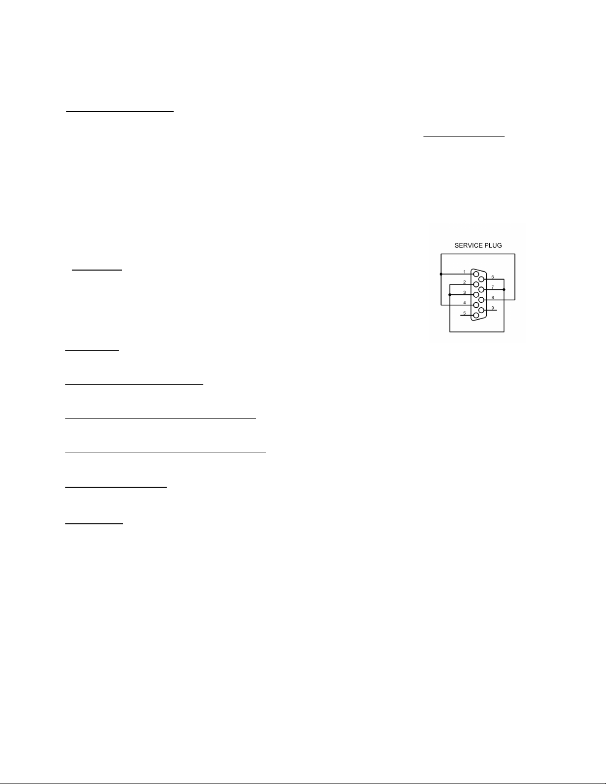
Service Plug
If you wish to make a service plug to automatically start the projector for bench testing
purposes you can wire a 9pin DB 9 connector as shown in the diagram.
Alternatively we can supply s
uch a plug complete with a Bi-colour LED for a small charge.
Please contact us for details using sales@stanwaxlaser.co.uk
Using XLR leads for e-stop
As the stop system here uses just
3 pins we recommend connecting the projectors and the
e-stop using industry standard XLR leads. This makes hook-up relatively cheap and often
the run from stage to FOH can be done using a spare in house patch. We have used this
system extensively for a number of years so can verify that it is robust.
The system we employ on our own projectors, uses adaptors that connect to the 9 pin Sub-d
remote interlock connection, and we have one lead with a 5 pin XLR that runs to the e-stop,
but use 3 pin links between the projectors. If you don’t wish to have the Bi-coloured Status
LED on your stop then you can use 3 pin leads throughout, including 3 pin male and female
sockets on the projector if you have the space on the rear panel.
We recommend having a female on the e-stop (we supply modified e-stops already wired
with 5 pin XLR connections) so that the male XLR is always facing towards the e
-stop. If you
employ this and the wiring standard shown right then connecting with other projectors owned
by other people and employing this system will always be a possibility.
XLR Pin Assignments
1 – Ground
2 – Stop
3 – Start
Optional connections to E-stop only
4 – Bi-LED
5 – Bi-LED (flat)
Table of contents
Other Stanwax Laser Computer Hardware manuals


Popular Computer Hardware manuals by other brands

Alphacool
Alphacool GPX-A 280-M10 instruction manual

ekwb
ekwb EK-Vector Strix RTX 2070 Backplate Installation and mounting manuals

Triax
Triax TMB 1500 user manual

Cypress Semiconductor
Cypress Semiconductor PSoC FirstTouch CY3261A-RGB Specifications

HighPoint
HighPoint RocketRAID 3700 Series Quick installation guide

Davicom
Davicom EPD driver development kit user guide


