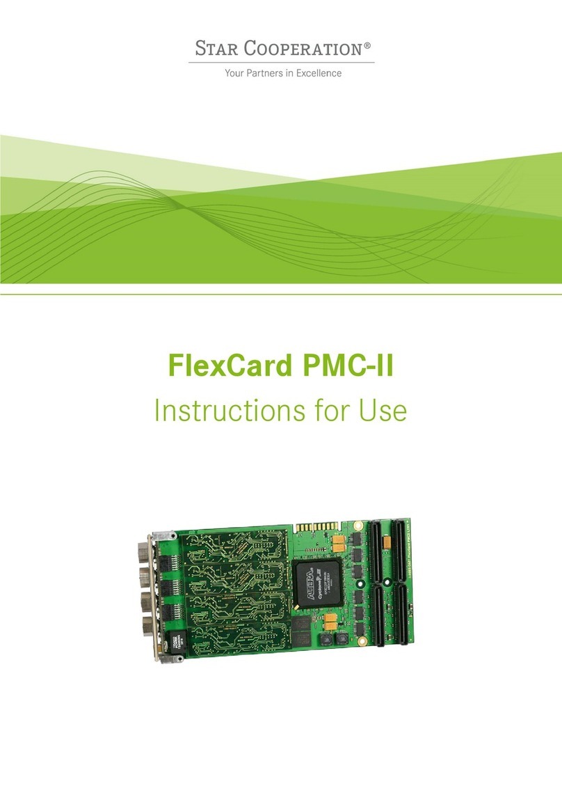
Star Cooperation FlexCard PMC-II User manual

FlexCard PMC-II
Instructions for Use

Created by STAR ELECTRONICS GmbH & Co. KG
Date created 2022-02-14 Date modified 2022-02-14 Page 2 of 44
3-0055-0P01-D05_FlexCard_PMC-II_Instructions_for_Use_D2V6-F.docx
NOTICE
ESD (Electro Static Discharge) sensitive product.
Refer to chapter 1.4 and follow the safety and handling instructions.
Contact Information
STAR ELECTRONICS GmbH & Co. KG
A Company of the STAR COOPERATION Group
Jahnstraße 86
73037 Göppingen
Phone: +49 (0)7031 6288-5656
Phone: +49 (0)7031 6288-5330 (Support)
Sales: sales-ee@star-cooperation.com
Support: support-ee@star-cooperation.com
www.star-cooperation.com/ee-solutions
Company Data
STAR ELECTRONICS GmbH & Co. KG, registered offices: Göppingen, register court Ulm, HRA 721096
Partner liable to unlimited extent: STAR ELECTRONICS Verwaltungs-GmbH, registered offices: Göppingen, register
court Ulm, HRB 722565
Represented by the executive board: Rolf Wittig, Henning Lange
Copyright Notice
2022 STAR ELECTRONICS GmbH & Co. KG. All Rights Reserved.
No part of this document may be reproduced in any form (photocopy, microfilm or another procedure) without
prior written consent from STAR ELECTRONICS GmbH & Co. KG
Trademarks
Any trademarks used in this document are the property of their respective owners.

Created by STAR ELECTRONICS GmbH & Co. KG
Date created 2022-02-14 Date modified 2022-02-14 Page 3 of 44
3-0055-0P01-D05_FlexCard_PMC-II_Instructions_for_Use_D2V6-F.docx
Disclaimer
The information contained in this document does not affect or change General Terms and Conditions of STAR
ELECTRONICS GmbH & Co. KG.STAR ELECTRONICS GmbH & Co. KG does not guarantee the completeness and
accuracy of the content of this document and assumes no responsibility for any errors which may appear in this
document or due to this document. The content of this document or the associated products are subject to
change without notice at any time.
Based on currently state of arts and science it is impossible to develop software that is bug-free in all
applications. Therefore, the product is only allowed to be used in the sense of the product use case described
herein.
STAR ELECTRONICS GmbH & Co. KG makes no warranty express or implied, as to this document or the
information content, materials or products for any particular purpose, nor does STAR ELECTRONICS GmbH & Co.
KG assume any liability arising out of the application or use of this product, and disclaims all liabilities, including
without limitation resulting damages, as permissible by applicable law.
All operating parameters which are provided in this document can vary in different applications or over time. The
herein described product solely is allowed to be used as described in chapter “Intended use”.
Without limiting the rights under copyright, no part of this document may be reproduced, stored in or introduced
into a retrieval system, or transmitted in any form or by any means (electronic, mechanical, photocopying,
recording, or otherwise), or for any purpose, without the express written consent of STAR ELECTRONICS GmbH &
Co. KG.
STAR ELECTRONICS GmbH & Co. KG may have patents, patent applications, trademarks, copyrights, or other
intellectual property rights covering subject matter in this document. Except as expressly stated in a written
license agreement from STAR ELECTRONICS GmbH & Co. KG,the furnishing of this document does not give you
any license to these patents, trademarks, copyrights, or other intellectual property.
Any semiconductor devices have an inherent chance of failure. You have to protect against injury, damage or loss
from such failures by incorporating safety design measures into your facility and equipment such as redundancy,
fire protection, and prevention of over-current levels and other abnormal operating conditions.
The safety and handling instructions in this document have to be followed strictly.
EC Conformity
The FlexCard PMC-II complies with the essential requirements of the following applicable European Community
Directive(s) including current amendments, and carries the CE marking accordingly:
2014/30/EU EMC Directive
The following standard(s) have been used to assess the product:
EN 61000-4-2:2009
EN 61000-4-3:2006 + A1:2008 + A2:2010
EN 61000-4-4:2012
EN 61000-4-6:2014
EN 55024:2010 + A1:2015
The FlexCard PMC-II is designed, intended and authorized for industrial use only. Using the product in domestic
environment may lead to electromagnetic disturbances.
This product is compliant with the European Community Directive 2011/65/EC on the restriction of the use of
certain hazardous substances in electrical and electronic equipment (RoHS).
UK Conformity
The FlexCard PMC-II complies with the essential requirements of the following applicable UK Regulations including
current amendments, and carries the UK marking accordingly:
2016 Electromagnetic Compatibility Regulations

Created by STAR ELECTRONICS GmbH & Co. KG
Date created 2022-02-14 Date modified 2022-02-14 Page 4 of 44
3-0055-0P01-D05_FlexCard_PMC-II_Instructions_for_Use_D2V6-F.docx
The following standard(s) have been used to assess the product:
EN 61000-4-2:2009
EN 61000-4-3:2006 + A1:2008 + A2:2010
EN 61000-4-4:2012
EN 61000-4-6:2014
EN 55024:2010 + A1:2015
The FlexCard PMC-I is designed, intended, and authorized for industrial use only. Using the product in domestic
environment may lead to electromagnetic disturbances.
This product is compliant with “the Restriction of the Use of Certain Hazardous Substances in Electrical and
Electronic Equipment Regulations 2012”.
Revision History
Version
Date
Description
D1V0-F 27-Feb-2009 Initial release.
D1V1-F 16-Apr-2009 Added FlexTiny II chapter and Linux driver support.
D1V2-F 10-Jul-2009 Updated firmware update chapter and added Xenomai driver support.
D1V3-F 30-Jul-2009 Added user card id chapter. Changed interface description.
D1V4-F
11-Dec-2009
Updates for driver version S6V2-F.
D1V5-F
28-May-2010
Updates for driver version S6V3-F.
D1V6-F 05-Oct-2010 Updates for Linux/Xenomai driver version S5V3-F.
D1V7-F 06-Jul-2012 Updates for Windows driver version S6V4-F.
D2V0-F 16-Nov-2015 Layout updated to STAR COOPERATION.
D2V1b-F 22-Jun-2016 Added CAN FD, driver version S6V6-F
D2V2-F 16-Sep-2016 Update for Windows 10
D2V3a-F 06-Dec-2018 Added support for Windows Secure Boot.
Removed support for Windows XP/Vista, LabVIEW.
D2V3b-F 10-Dec-2018 Added support for Linux Driver S6V6-F
D2V4-F 08-Dec-2020 Removed support for Windows 7
D2V5-F 25-Aug-2021 Updated legal information
Updated description for mounting FlexTiny II modules
Changed list of supported software (Caromee is no longer supported)
D2V6-F 14-Feb-2022 Updated chapter EC Conformity
Added chapter UK Conformity
Related Hardware / Software Versions
Product Reference No. Version
(Major and
Minor)
Remarks
FlexCard PMC-II Hardware 3-00550A01 H1V1 PMC II card with 2 triggers and FlexRay and
CAN support depending on the available
FlexTiny II
FlexCard PMC-II Hardware 3-00550A02 15 PMC II card with 2 triggers and support for
FlexRay, CAN, CAN-FD, Ethernet or BRR
depending on the available FlexTiny II
FlexCard PMC-II Firmware 3-0055-0C01 S6V6
(6.5.0.33)
Maximum 4 FlexRay or 8 CAN channels with
DMA support.

Created by STAR ELECTRONICS GmbH & Co. KG
Date created 2022-02-14 Date modified 2022-02-14 Page 5 of 44
3-0055-0P01-D05_FlexCard_PMC-II_Instructions_for_Use_D2V6-F.docx
Product Reference No. Version
(Major and
Minor)
Remarks
FlexTiny II FR 3-00560A01 13 Physical layer board for FlexRay
FlexTiny II CAN-HS 3-00560B01 13 Physical layer board for CAN-HS
FlexTiny II Ethernet 3-00560D01 10 Physical layer board for Ethernet
FlexTiny II CAN-FD
3-00560G01
10
Physical layer board for CAN-FD
FlexTiny II BRR
3-00560H01
20
Physical layer board for 100BASE-T1
fcBase API (Windows)
3-0009-0K03
S6V8
API to build your own application
fcBase API (Linux) 3-0009-0U01 S6V6 API to build your own application
fcBase API (Xenomai) 3-0009-0V01 S6V5 API to build your own application
Further related hardware and software can be found in chapter 2.2.

Created by STAR ELECTRONICS GmbH & Co. KG
Date created 2022-02-14 Date modified 2022-02-14 Page 6 of 44
3-0055-0P01-D05_FlexCard_PMC-II_Instructions_for_Use_D2V6-F.docx
Contents
1General ..................................................................................................................................................8
1.1 Intended User Group............................................................................................................................8
1.2 Intended use........................................................................................................................................8
1.3 Used Pictograms..................................................................................................................................9
1.4 Safety and Handling Instructions........................................................................................................10
1.5 Meaning of Text Styles .......................................................................................................................12
2Product Description ........................................................................................................................... 13
2.1 FlexCard PMC-II at a glance ...............................................................................................................13
2.2 Scope of Supply.................................................................................................................................14
2.3 Accessory Parts .................................................................................................................................15
2.4 Updates.............................................................................................................................................15
3Technical Data.................................................................................................................................... 16
3.1 Electrical Characteristics ...................................................................................................................16
3.1.1 Power consumption ...........................................................................................................................16
3.1.2 Signal range.......................................................................................................................................16
3.2 Physical Characteristics .....................................................................................................................16
3.3 Environmental Conditions ..................................................................................................................16
3.4 Block Diagram ...................................................................................................................................17
3.5 Interfaces and Connectors .................................................................................................................17
3.5.1 PMC Interface....................................................................................................................................18
3.5.2 Bus Interfaces on the Front Panel.......................................................................................................18
3.5.3 Bidirectional Trigger Connectors on the Front Panel ...........................................................................20
3.5.4 LED Indicators on the Front Panel ......................................................................................................21
3.5.5 FlexTiny II Modules ............................................................................................................................21
3.5.6 FlexTiny II ISO ....................................................................................................................................22
3.5.7 Mounting the FlexTiny II Modules .......................................................................................................22
4Getting Started................................................................................................................................... 24
4.1 Assembly and Line-up ........................................................................................................................24
4.2 Hardware Installation and Maintenance..............................................................................................24
4.2.1 Customize the Bus Driver Terminating Resistor Values .......................................................................25
4.3 Software Installation and Update .......................................................................................................25
4.3.1 Preconditions.....................................................................................................................................25
4.3.2 Installation on Microsoft Windows Operating Systems........................................................................26
4.3.3 Uninstallation on Microsoft Windows Operating Systems....................................................................29
4.3.4 Installation on Linux Operating System...............................................................................................29
4.4 Firmware Update ...............................................................................................................................29
4.5 License Update..................................................................................................................................32
4.6 Activate an Application Image ............................................................................................................34
4.7 UserCardID ........................................................................................................................................34
4.8 Licensing ...........................................................................................................................................34
5Configuration and Operation ............................................................................................................. 35
6Shipping, Maintenance and Disposal................................................................................................. 36
7Troubleshooting ................................................................................................................................. 37
8Ordering Information ......................................................................................................................... 40

Created by STAR ELECTRONICS GmbH & Co. KG
Date created 2022-02-14 Date modified 2022-02-14 Page 7 of 44
3-0055-0P01-D05_FlexCard_PMC-II_Instructions_for_Use_D2V6-F.docx
8.1 FlexCard PMC-II .................................................................................................................................40
8.2 Accessory Parts .................................................................................................................................40
8.3 Related Documents............................................................................................................................41
9Appendix............................................................................................................................................. 42
9.1 Appendix A: Guideline for handling ESD sensitive Products.................................................................42
9.2 Appendix B: .......................................................................................................................................42
9.2.1 Acronyms and Abbreviations ..............................................................................................................42
9.2.2 List of Tables .....................................................................................................................................43
9.2.3 List of Figures ....................................................................................................................................43

Created by STAR ELECTRONICS GmbH & Co. KG
Date created 2022-02-14 Date modified 2022-02-14 Page 8 of 44
3-0055-0P01-D05_FlexCard_PMC-II_Instructions_for_Use_D2V6-F.docx
1General
1.1 Intended User Group
This product may only be used by expert technicians and/or engineers who are qualified and familiar with
electronic components and systems.
Each person involved with setup or operation of the product must
be a qualified technician or engineer
strictly adhere to this manual
receive a briefing by an authorized person
NOTICE
If you are unsure of how to use the product as intended or have any questions about the
use of the product, please discontinue use of the product immediately and contact the
STAR ELECTRONICS GmbH & Co. KG Support.
WARNING
The product may only be used by expert technicians and/or engineers who are qualified
and familiar with electronic components and systems!
The use of the product by non-professionals is not permitted and strictly forbidden!
The FlexCard PMC-II is a testing equipment. It was developed to test the communication behavior of
automotive bus systems and Ethernet together with Electronics Control Units and sensors in a fully
controlled testing and/or laboratory environment.
For this intended use, the FlexCard PMC-II offers the following options:
-Transmit and receive data (e.g. Use Case “Remaining Bus Simulation”).
-Exchange of data traffic between two or more bus systems (e.g. Use Case “Gateway”)
-Manipulation of data traffic (e.g. Use Case “Manipulation of signal values based on user
configuration”)
-Recording of data traffic (e.g. Use Case “Logging”)
Any deviation from the intended use and/or installation in a testing vehicle is only permitted with specific
prior written approval of STAR ELECTRONICS GmbH & Co. KG.
WARNING
The FlexCard PMC-II may be used to communicate with networked electronic systems.
E.g. FlexRay, CAN or Ethernet.
Any use of the product outside a fully controlled testing and/or laboratory environment
may result in death or serious injury due to unpredictable behavior of a vehicle and/or
potentially missing, deactivated, or malfunctioning safety devices on a vehicle!
The user is responsible to ensure the safety of the entire system. This includes amongst
other things a safety shutdown.

Created by STAR ELECTRONICS GmbH & Co. KG
Date created 2022-02-14 Date modified 2022-02-14 Page 9 of 44
3-0055-0P01-D05_FlexCard_PMC-II_Instructions_for_Use_D2V6-F.docx
NOTICE
The device is not a calibrated measurement device. STAR ELECTRONICS GmbH & Co. KG
accepts no liability whatsoever for the correctness of any measurement results.
WARNING
The FlexCard PMC-II is NOT designed, intended, or authorized and may NOT be used for
or in connection with the following purposes and/or devices:
- use as part of medical systems
- life support applications
- aviation, space, nuclear, or military applications
- use in areas where combustible or explosive gas mixtures are likely to occur
- any other purposes / devices deviating from the intended use of the product
specified by STAR ELECTRONICS GmbH & Co. KG.
WARNING
The product may only be used by expert technicians and/or engineers who are qualified
and familiar with electronic components and systems!
The use of the product by non-professionals is not permitted and strictly forbidden!
1.3 Used Pictograms
The meaning of used pictograms is shortly described below.
Follow the specific instructions in the document where these pictograms are placed.

Created by STAR ELECTRONICS GmbH & Co. KG
Date created 2022-02-14 Date modified 2022-02-14 Page 10 of 44
3-0055-0P01-D05_FlexCard_PMC-II_Instructions_for_Use_D2V6-F.docx
WARNING
Used to indicate a potentially hazardous situation which,
if not avoided, could result in death or serious injury.
CAUTION
Used to indicate a potentially hazardous situation which,
if not avoided, could result in minor or moderate injury.
NOTICE
Used to indicate a situation which may result in an operating failure.
Damage of the product may occur, but there is no hazard of injury
if not avoided.
NOTICE
Used to indicate an electrostatic discharge sensitive product.
The product is subject to damage by ESD, if no precautions are taken.
Information
Used to indicate information provided only for purposes of clarification, illustration, and
general information.
Reference
References to other documents.
Product marking which shows the compliance of the product with the European Waste
Electrical and Electronic Equipment Directive 2012/19/EC.
1.4 Safety and Handling Instructions
Please read the instructions for use carefully. To protect the device or the application against damage or to
avoid personal injury the FlexCard PMC-II has to be handled as described herein.
Changes or modifications of the FlexCard PMC-II are not allowed for safety and warranty reasons!
STAR ELECTRONICS GmbH & Co. KG is not liable for any damages arising from non-observance of the product
information.
Follow the
a) specific safety and handling instructions placed at dedicated document positions
b) general safety and handling instructions below:

Created by STAR ELECTRONICS GmbH & Co. KG
Date created 2022-02-14 Date modified 2022-02-14 Page 11 of 44
3-0055-0P01-D05_FlexCard_PMC-II_Instructions_for_Use_D2V6-F.docx
WARNING
MAINS VOLTAGE UP TO 110 / 230 VAC AT THE COMPUTER CHASSIS
ELECTRICAL SHOCK HAZARD!
TO PREVENT DEATH, PERSONAL INJURY OR DAMAGE:
DISCONNECT THE POWER CABLE OF THE COMPUTER BEFORE OPENING THE
CHASSIS.
CAUTION
TO PREVENT PERSONAL INJURY, TO PREVENT DAMAGE TO THE
FlexCard PMC-II OR TO PREVENT CONSEQUENTIAL DAMAGES:
PLEASE OBSERVE THE ESD-PROTECTION INSTRUCTIONS BEFORE GETTING IN
CONTACT WITH THE CONNECTORS. OTHERWISE THE FLEXCARD PMC-II MAY
GET DAMAGED. SEE CHAPTER 9.1.
DO NOT CONNECT ANY OTHER SIGNALS TO THE INTERFACES AS DESCRIBED
IN THE CHAPTER “INTERFACES AND CONNECTORS”.
ENSURE THAT ALL SIGNALS ARE WITHIN THE SPECIFIED RANGE.
IT IS RECOMMENDED TO ONLY USE PRODUCTS FROM STAR ELECTRONICS
GMBH & CO. KG LISTED IN CHAPTER 8.2 ACCESSORY PARTS TO ENSURE
PROPER FUNCTION!
HIGH TEMPERATURES CAN DAMAGE THE FLEXCARD PMC-II
. KEEP THE
FLEXCARD PMC-II AWAY FROM HEATERS, STOVES, FIREPLACES, AND OTHER
SOURCES OF HEAT.
DO NOT EXPOSE THE FLEXCARD PMC-II TO RAIN OR USE IT NEAR WATER.
DO NOT USE THE FLEXCARD PMC-II IN AREAS OF EXPLOSION HAZARD.
NOTICE
The FlexCard PMC-II may not work correctly or communication problems may occur if:
The FlexCard PMC-II is used in existing passive networks, i.e. when changing the topology
structure.
The coded 8-pole FlexRay connectors are inserted wrong (i.e. due to forced insertion).
The bus termination of the FlexCard PMC-II is not adapted to the connected bus topology.
The FlexCard PMC-II is configured wrong.

Created by STAR ELECTRONICS GmbH & Co. KG
Date created 2022-02-14 Date modified 2022-02-14 Page 12 of 44
3-0055-0P01-D05_FlexCard_PMC-II_Instructions_for_Use_D2V6-F.docx
NOTICE
ESD (Electro Static Discharge) sensitive product
STAR ELECTRONICS GmbH & Co. KG products lacking protective enclosures
are subject to damage by ESD.
Take proper ESD precautions to avoid
performance degradation or loss of functionality!
Unpack, handle or operate these products only in environments where sufficient
precautionary measures have been taken in respect to ESD hazards.
A guideline is available in chapter 9.1.
Only appropriately trained personnel (such as electricians, technicians and
engineers) may handle and/or operate these products.
1.5 Meaning of Text Styles
In this document filenames are marked with a different text format.

Created by STAR ELECTRONICS GmbH & Co. KG
Date created 2022-02-14 Date modified 2022-02-14 Page 13 of 44
3-0055-0P01-D05_FlexCard_PMC-II_Instructions_for_Use_D2V6-F.docx
2Product Description
2.1 FlexCard PMC-II at a glance
The FlexCard PMC-II is a flexible multi-bus instrument for
monitoring, testing, simulation and basic gateway applications. It
is intended to be used with the various automotive network
systems. The number of interfaces may easily be varied by
mounting up to four FlexTiny II modules. This ensures a free and
future-oriented field of application.
Several features like switchable bus terminations, two trigger
lines as well as the easily updateable firmware are integrated on
the device. Using different monitoring modes, the card can be
used as pure monitoring tool and as real communication node for
FlexRay, CAN and Ethernet. Additionally, if the firmware image
with one FlexRay CC is used, the FlexCard PMC-II supports Self-
Synchronization through a second sync frame.
The FlexCard PMC-II can be inserted in a 32bit/33MHz capable
PMC chassis or carrier module. Such carrier modules are available for several platforms like PCI, PCIe,
CompactPCI, or PXI.
The bus systems are connected via four Binder Series 712 jacks. Each Binder jack connects either channel
A and B for FlexRay or two bus channels for CAN or one channel for Ethernet. For each channel two LED
indicators are provided on the front panel signaling different states of the bus channels.
Up to API- and FW-Version S5V2-F, all incoming data is temporarily stored into the 2 MB onboard buffer of
the device. 1 MB is used for data buffering, 1 MB for internal processes. From API- and FW-Version S6V1-F,
all incoming data is transferred over DMA from device to the system RAM and temporarily stored into a 2
MB receive buffer. From API- and FW-Version S6V3-F, all incoming data is temporarily stored into the 2 MB
onboard buffer of the device, too. This prevents data losses and flexible data collection cycles become
possible. Transmit data will be written directly into the Communication Controller in order to ensure a
maximum of performance.
Reference
Further information about how to program applications for the FlexCard PMC-II can be
found in the FlexCard API Documentation.
FEATURES
32bit/33MHz PCI Mezzanine
Card device
4 slots for FlexTiny II
modules, allows maximum 4
channels FlexRay (A+B), 8
channels CAN, 1 channel
Ethernet or a combination
2 TTL compatible trigger lines
Firmware updateable

Created by STAR ELECTRONICS GmbH & Co. KG
Date created 2022-02-14 Date modified 2022-02-14 Page 14 of 44
3-0055-0P01-D05_FlexCard_PMC-II_Instructions_for_Use_D2V6-F.docx
Information
The currently supported FlexRay Communication Controller type on the
FlexCard PMC-II is:
BOSCH E-Ray FlexRay IP-Module, Release 1.3
(Referring to the FlexRay protocol specification v2.1a)
The currently supported CAN Communication Controller types (depending on the
firmware image) on the FlexCard PMC-II are:
BOSCH D_CAN CAN IP-Module Release 1.1.1
(Referring to the CAN protocol specification v2.0 part A, B)
BOSCH M_CAN CAN IP-Module Release 3.2.1
(Referring to the CAN protocol specification “ISO 11898-1:2015” and “Bosch CAN FD
specification 1.0”)
Other versions are not supported up to now. Please contact STAR ELECTRONICS
GmbH & Co. KG if other versions need to be supported.
The firmware can be exchanged using the update tool FlexUpdate.exe.
Applications
Usage with STAR ELECTRONICS GmbH & Co. KG FlexAlyzerV2 (See chapter 2.2)
Further commercial applications will support FlexCard PMC-II soon
Usage with customer specific software. The FlexCard driver has a C-API, see [1].
2.2 Scope of Supply
The FlexCard PMC-II is delivered with
Product Reference No. Version
(Major and Minor)
Remarks
FlexCard PMC-II
Firmware
3-0055-0C01 S6V6 (6.5.0.33),
S6V5 and S5V3
Maximum 4 FlexRay, 8 CAN
channels or a combination.
FlexCard SYS 3-0009-0E04 S6V8 Required low level driver for the
FlexCard.
FlexCard DLL 3-0009-0K03 S6V8 Required high level driver for the
FlexCard.
FlexCard Linux driver 3-0009-0U01 S6V6 Linux driver for the FlexCard.
FlexCard Xenomai driver 3-0009-0V01 S6V5 Xenomai driver for the FlexCard.
FlexAlyzerV2 3-0038-0B01 S1V4 FlexCard monitoring tool.
Supports FlexRay/CAN
monitoring and sending data,
triggers, filters and data logging.
Instructions for Use 3-0055-0P01-D05 See above This document.
FlexCard API
Documentation
3-0009-0S01-D03 D2V5 FlexCard API programming
manual as PDF file.
Getting Started Manual 3-0055-0P01-D07 D2V0 Example how to build a small
FlexRay/CAN-communication.
Demo - S1V6 Demo explaining the
programming of the FlexCard.

Created by STAR ELECTRONICS GmbH & Co. KG
Date created 2022-02-14 Date modified 2022-02-14 Page 15 of 44
3-0055-0P01-D05_FlexCard_PMC-II_Instructions_for_Use_D2V6-F.docx
Product Reference No. Version
(Major and Minor)
Remarks
DemoPMC - S1V5 Demo explaining the
programming of the FlexCard
with multiple FlexRay CCs.
DemoCAN - S1V5 Console application explaining
the communication over CAN.
DemoCANFD - S1V0 Console application explaining
the communication over CAN FD.
DemoUartOverCan - - Console application explaining
the communication over
UartOverCan.
CanBaudRateCalculator - S1V7 Helps with the calculation of CAN
bus parameters.
FlexUpdate - S1V11 Tool for updating firmware and
licenses.
Tracer Control - S1V3 Activates debug information.
Table 1: Scope of supply of the FlexCard PMC-II
A list of available accessory parts can be found in chapter 8.2.
2.3 Accessory Parts
For further information about accessories for the FlexCard PMC-II see chapter 8.2 Accessory Parts.
NOTICE
Use only accessories from STAR ELECTRONICS GmbH & Co. KG listed in chapter 8.2
Accessory Parts to ensure proper function and for warranty reasons!
Other accessories without prior written consent of STAR ELECTRONICS GmbH & Co. KG
must not be used.
2.4 Updates
Information
Updates regarding the FlexCard drivers and firmware are possible via web-downloads
from the STAR ELECTRONICS GmbH & Co. KG homepage.
The firmware on the FlexCard PMC-II can be updated with an appropriate software tool,
see chapter 4.3.2.
If you mount an additional or different FlexTiny II module, a license update could be
necessary. See chapter 4.5 on how to update your license.

Created by STAR ELECTRONICS GmbH & Co. KG
Date created 2022-02-14 Date modified 2022-02-14 Page 16 of 44
3-0055-0P01-D05_FlexCard_PMC-II_Instructions_for_Use_D2V6-F.docx
3Technical Data
3.1 Electrical Characteristics
3.1.1 Power consumption
The necessary power is directly provided by the PCI bus through the PMC interface. The typical power
consumption when operating the FlexCard PMC-II is 1.6 W. The FlexCard PMC-II requires both the +3.3 V and
+5 V power rail, so in the following table the total power consumption is the sum of the power consumption
of each power rail.
Supply voltage +3.3 VDC +5.0 VDC
Supply current (typical) 100 mA 250 mA
Table 2: Power consumption
3.1.2 Signal range
Maximum voltage input on a FlexRay BP/BM
(FlexTiny II FR) +60.0 V
Minimum voltage input on a FlexRay BP/BM
(FlexTiny II FR) -60.0 V
Maximum voltage input on a CAN high/low
(FlexTiny II CAN-HS)
+40.0 V
Minimum voltage input on a CAN high/low
(FlexTiny II CAN-HS) -27.0 V
Maximum voltage input on a CAN high/low
(FlexTiny II CAN FD) +40.0 V
Minimum voltage input on a CAN high/low
(FlexTiny II CAN FD) -40.0 V
Table 3: Signal range
3.2 Physical Characteristics
CPU of FlexCard PMC-II
Altera Cyclone III
Bus Interfaces
Bus Drivers on FlexTiny II
Bus Termination
Bus state LEDs
8 bus channels provided on the front panel
FlexRay: NXP TJA1080 Transceivers
CAN: NXP TJA1041 CAN HS Transceivers
CAN FD: NXP TJA1044GT CAN FD Transceivers
Ethernet: Texas Instruments DP83640
The bus termination can be switched by software. CAN/
CAN FD is terminated with 120Ω, FlexRay with 90Ω
Two LED-indicators per channel
Synchronization Interfaces on the front panel 2x 5V TTL trigger connectors provided on the front panel
Weight 100 g
Dimensions L x W x H without connectors
approx. 157 x 74 x 14 mm³
Table 4: Physical characteristics of the FlexCard PMC-II
3.3 Environmental Conditions
Temperature Operating: -40 to +70°C
Storage: -40 to +85°C
Relative Humidity Operating: 10% to 90% rH, non-condensing
Storage: 10% to 90% rH, non-condensing
Table 5: Environmental conditions for the FlexCard PMC-II

Created by STAR ELECTRONICS GmbH & Co. KG
Date created 2022-02-14 Date modified 2022-02-14 Page 17 of 44
3-0055-0P01-D05_FlexCard_PMC-II_Instructions_for_Use_D2V6-F.docx
3.4 Block Diagram
Figure 1: The FlexCard PMC-II in a functional environment
Reference
Further information about the usage of FlexAlyzerV2 and FlexConfig can be found in [3],
[4], [5].
3.5 Interfaces and Connectors
Read and follow these instructions when connecting and using the FlexCard PMC-II:

Created by STAR ELECTRONICS GmbH & Co. KG
Date created 2022-02-14 Date modified 2022-02-14 Page 18 of 44
3-0055-0P01-D05_FlexCard_PMC-II_Instructions_for_Use_D2V6-F.docx
NOTICE
Ensure that all signal lines connected to the FlexCard PMC-II are in the allowed range.
Be sure to connect all cables as described in this manual.
It is recommended to only use cables from STAR ELECTRONICS GmbH & Co. KG. See
Chapter 8.2 Accessory Parts.
The cables for the bus channels should always be fixated by screwing the plug into the
jack.
Ensure to grasp the plug and not the cable when disconnecting the
FlexCard PMC-II.
3.5.1 PMC Interface
The FlexCard PMC-II can be used in PCI slots with 3.3V signaling and slots with 5V signaling. The FlexCard
PMC-II is running on 32 Bit PCI. Figure 2 describes how to identify a PCI slot with 3.3V signaling and a slot
with 5V signaling.
Figure 2: Top view of a motherboard. Connectors of the PCI card are at the left side. At the top is a PCI slot with 5V
signaling; below is a PCI slot with 3.3V signaling.
3.5.2 Bus Interfaces on the Front Panel
On the front panel, four Binder series 712 jacks are provided for the bus connections.
Figure 3: Front panel
One bus connector may contain either FlexRay channel A and B, two CAN channels or one Ethernet channel.
For both bus types (FlexRay and CAN), the same pin assignment and the same cables are used. Physically,
the differentiation between the bus systems is only done by the FlexTiny II modules.
The pin assignment of the FlexCard PMC-II connectors is shown in Figure 3 and is listed in Table 5. Whether
FlexRay, CAN or CAN FD is connected depends on the mounted FlexTiny II module. When using isolated
FlexTiny II modules both pin 2 and pin 8 are isolated grounds.

Created by STAR ELECTRONICS GmbH & Co. KG
Date created 2022-02-14 Date modified 2022-02-14 Page 19 of 44
3-0055-0P01-D05_FlexCard_PMC-II_Instructions_for_Use_D2V6-F.docx
Figure 4: Front panel jack pin assignment, front view of the 8 pin Binder 712 female connector
Pin number
Binder 712 female
Signal Color
1
Shield
2
GND
3
Interface 1: FlexRay BusPlus or CAN high
4
Interface 1: FlexRay BusMinus or CAN low
5
Interface 2: FlexRay BusPlus or CAN high
6
Interface 2: FlexRay BusMinus or CAN low
7
Not connected
8
GND
Table 6: FlexCard PMC-II Binder connector assignment
The FXC FCL8-2 Cable (Ref. No. 3-0034-1L01) has a female Binder 722 connector (See Figure 4) and two
female SubD connectors (See Figure 5). One connector is labeled as Channel A, it carries FlexRay channel
A or CAN interface 1, 3, 5 or 7. The second connector is labeled as Channel B and it carries FlexRay
channel B or CAN interface 2, 4, 6 or 8, depending on the Binder 722 jack it is connected to.
This cable is suitable for connecting a FlexTiny II FR, FlexTiny II CAN-HS, or FlexTiny II CAN FD.
Figure 5: SubD9 pin assignment, front view
Pin number
SubD9 female
Signal Color
1
Not connected
2
Interface 1: FlexRay BusMinus or CAN low
3
GND
4
Not connected
5
Shield
6
Not connected
7
Interface 1: FlexRay BusPlus or CAN high
8
Not connected
9
Not connected
Table 7: FXC FCL8-2 Cable (Ref. No. 3-0034-1L01) SubD9 cable assignment, first male connector

Created by STAR ELECTRONICS GmbH & Co. KG
Date created 2022-02-14 Date modified 2022-02-14 Page 20 of 44
3-0055-0P01-D05_FlexCard_PMC-II_Instructions_for_Use_D2V6-F.docx
Pin number
SubD9 female
Signal Color
1
Not connected
2
Interface 2: FlexRay BusMinus or CAN low
3
GND
4
Not connected
5
Shield
6
Not connected
7
Interface 2: FlexRay BusPlus or CAN high
8
Not connected
9
Not connected
Table 8: FXC FCL8-2 Cable (Ref. No. 3-0034-1L01) SubD9 cable assignment, second male connector
Information
The FC Daisy Chain FR 2 Cable is available for the FlexCard PMC-II.It connects 4 Sub-D
jacks to the FlexCard. Therefore four bus nodes may be connected. See Chapter 8.2 for
ordering information.
3.5.3 Bidirectional Trigger Connectors on the Front Panel
For synchronization purposes, the FlexCard PMC-II provides two 5V tolerant TTL-compatible trigger
connectors (Trig1 and Trig2, see Figure 2) on the front panel. The device has the ability to receive and
generate trigger events on both trigger connectors. This feature allows e.g. a synchronization of different
bus analyzing devices.
Physically, the triggers are MMCX-male-connector for coax-cables. The electrical characteristic of this output
is described in Table 9. The values are the same for a PCI slot with 3.3 V signaling and for a slot with 5 V
signaling.
Parameter
Min
Typ
Max
Units
Input High Voltage
2.4
-
5
V
Input High Current
4
-
12
mA
Input Low Voltage
-
-
0.8
V
Output High Voltage
4
4.5
5
V
Output High Current
-
4
10
mA
Output Low Voltage
0
0.5
0.8
V
Table 9: Electrical characteristic of trigger connections
Both trigger connectors can freely be configured by software to act as input or as output. The input trigger
can be programmed to work with rising or falling edges, while the output trigger of the FlexCard PMC-II is
always low-active.
Reference
Detailed information about how the trigger events are used with the
FlexCard PMC-II can be found in the FlexCard API Documentation.
Other manuals for FlexCard PMC-II
1
Table of contents
Other Star Cooperation Computer Hardware manuals
Popular Computer Hardware manuals by other brands

Renesas
Renesas Converter Board for M32171FxxFP M32171T-PTC user manual

hilscher
hilscher CIFX M223090AE-CO/F user manual

XMOS
XMOS XK-XMP-64 quick start guide

Alphacool
Alphacool EISBLOCK AURORA ACRYL GPX-A RADEON RX 6700XT MERC 319 INCL.... manual

Sony
Sony BKM-101C Service manual

Renesas
Renesas Emulation Pod for M16C/80 Group MCUs... user manual