Star EV 48U-2-DC-ADS User manual
Owner’s Manual and Service Guide
U-Series:
48U-2-DC-ADS, 72U-2-AC, 48U-HA1-DC-ADS (Cab by Curtis)
and 72U-HA1-AC-ADS (Cab by Curtis)

2
Thanks for buying the Star EV U-Series. This manual contains infor-
mation you will need for proper operation, maintenance, and care of
your U-Series. A thorough understanding of these simple instructions
will help you to obtain maximum enjoyment from your new Star EV.
If you have any questions about the operation or maintenance of
your U-Series, please consult your Star EV dealer.
Read and understand this manual completely before operating your
Star EV.
This manual should be considered a permanent part of your U-Series
and should remain with the vehicle when lending or resold.

3
Vehicle Specifications
Controls
Operational Process
Rules for safe operation
Maintenance
Battery maintenance
Transmission maintenance
Motor maintenance
Controller maintenance
Lubrication
General maintenance notes
Table of Contents
4
5
6
7
7
9
9
10
11
11

4
1: Vehicle Specifications
48U-2-DC-ADS 48U-HA1-DC-
ADS (Curtis Cab) 72U-2-AC 72U-HA1-AC-ADS
(Curtis Cab)
Passengers 2
Battery System Eight 6 V batteries, Trojan T-105 Twelve 6 V batteries, Trojan T-105
Motor Power 6.7 hp Advanced DC motor 10 hp AC motor
Controller Power 350 A Curtis programmable controller 550 A Curtis programmable controller
Top Speed 19.5 mph (20-25 mph if street legal)
Total Load Capacity 2200 lbs 2200 lbs 2200 lbs 2200 lbs
Dimensions 137” x 55” x 76”
(L x W x H)
137” x 57” x 74”
(L x W x H)
137” x 55” x 76”
(L x W x H)
137” x 57” x 74”
(L x W x H)
Box Dimensions 83” x 54” x 10” (L x W x H)
Weight w/ Batteries 2050 lbs 2460 lbs 2300 lbs 2710 lbs
Ground Clearance 5”
Turning Radius 13
Wheel Base 67”
Top Climbing Grade 20%
Body Material Steel
Front Suspension Independent, coil over shock
Rear Suspension Leaf spring and shock
Steering System Rack and pinion
Brake System Four-wheel hydraulic
Tire Size 155R12C, 8-ply DOT
Tire Pressure 65 psi
Wheel Type 12” steel
Cab Open cab with
canvas top
Solid doors with
slide-open win-
dows
Open cab with
canvas top
Solid doors with
slide-open win-
dows
Windshield Plexiglass AS1, DOT automo-
tive windshield Plexiglass AS1, DOT automo-
tive windshield
Drive Train Direct rear drive
Voltage Reducer 20 A, 48 V to 12 V reducer included 20 A, 72 V to 12 V reducer included
Warranty One year bumper-to-bumper warranty, less wear items
Two year Trojan battery warranty, based on date code
5
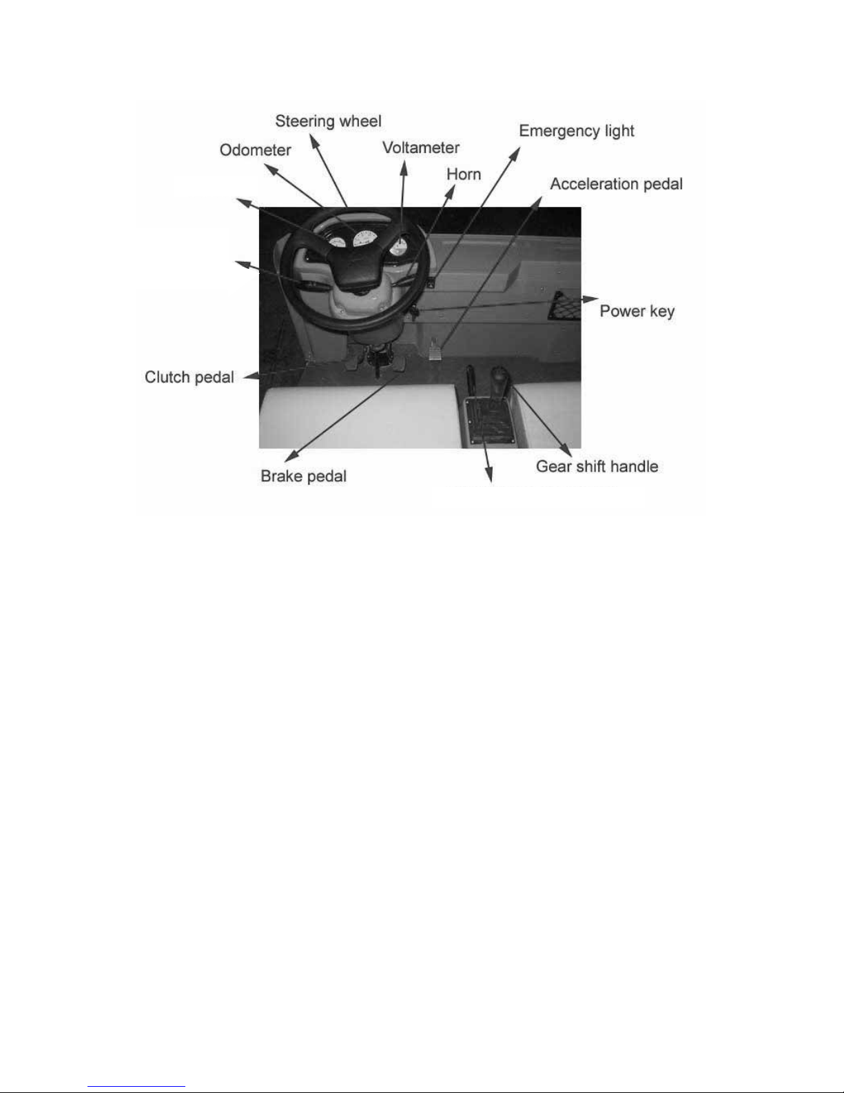
2: Controls
Ampmeter
Hand-brake lever
Power key: Controls the power supply of the whole vehicle. When the key is inserted
into it and turned clockwise, it will switch on the lights, horn, and the control sys-
tem; when the key is turned back, the power will be switched o.
Acceleration pedal: Controls the speed. It should be depressed slowly. The vehicle
speeds up with the gradual stepping-down, and reaches the full speed when the
pedal is stepped to the bottom. The vehicle slows down when the pedal is released
gradually. When the pedal is fully released, electric brake works.
Brake pedal: Decelerate or park the vehicle.
Hand-brake lever: Parks and brakes the vehicle.
Steering wheel: Controls the driving direction.
Light switch: Controls light system, including turning signals and headlight (in-
cludes high beam and lower beam).
Ampmeter: Indicates the current of the working vehicle.
Light switch
6
Voltameter: Indicates the voltage of the battery. It ranges from 20V to 60V from le to
right, including 3 sections highlighted by Red, Yellow and Green. Green represents
the battery is full in capacity. With the consumption of the power, the indicator
will fall from the right to the le gradually.
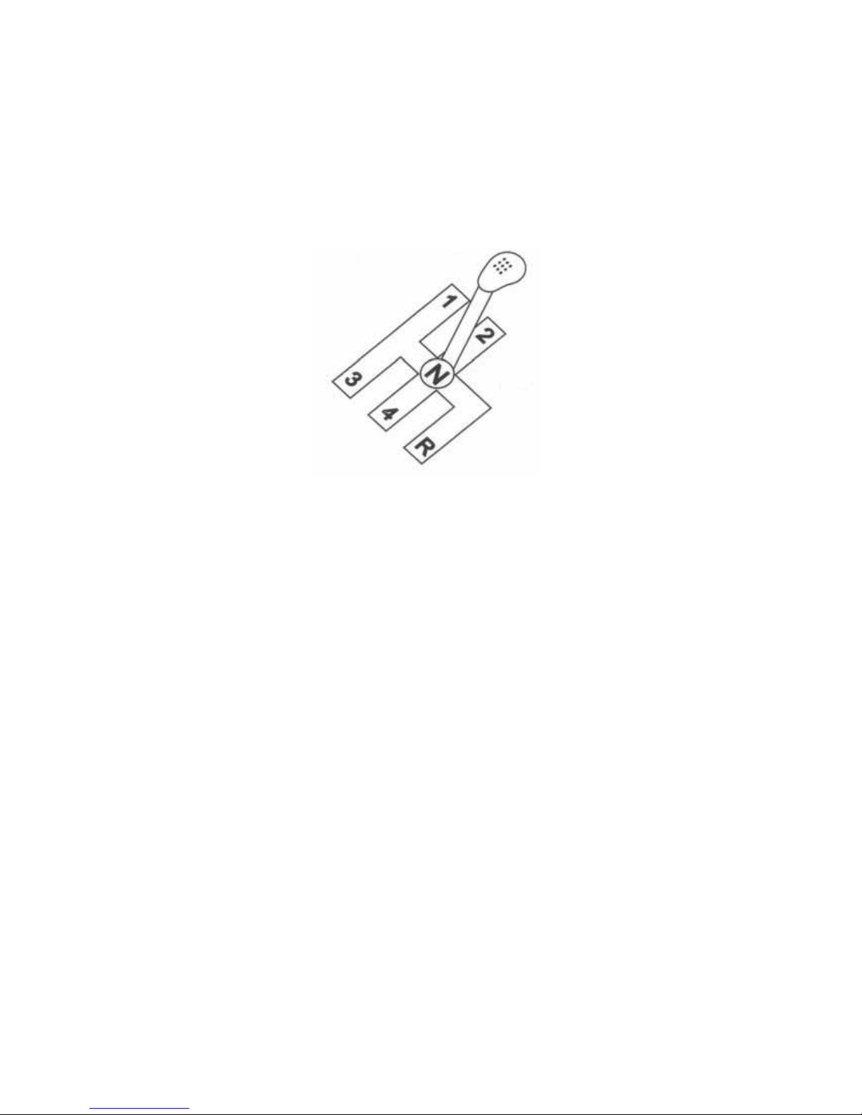
Gearshi: There are a total of totally 5 positions. Forward shi includes 1,2,3 and 4.
Reverse shi is R. It is recommended to use 1 for climbing an incline, and to use 2
and 3 for flat roads. It is not recommended to use 4 for driving.
3: Operational Process
1. Switch on the power key;
2. Step the clutch pedal to the bottom, select the right shi and make sure to
use right speed when driving. Selection standard is to make sure that the
working current of motor stays as small as possible as long as this current
is enough for driving.
3. Release the brake pedal.
4. Release the clutch pedal slowly.
5. Step down on the acceleration pedal smoothly, in this case, the vehicle
starts running.
WARNING: If you step down the acceleration pedal before switching on the power
key, the car will not run. In this case, you should release the acceleration pedal first,
and step it down again, then the vehicle will start running.

7
Rules for Safe Operation
The driver should have a good knowledge of the operation system of the vehicle
and its features, and follow the rules for safe operation as stated below:
• WARNING: Drive the vehicle o road unless it is allowed.
• The vehicle cannot be over-loaded, otherwise the motor will be damaged,
the vehicle will lose control and its life will be shortened.
• Unqualified persons are prohibited to drive the vehicle.
• Make sure this vehicle run in its rated climbing ability.
• Don’t overtake other vehicles at crossroad, in blind area or in other dan-
gerous zone.
4: Maintenance
Battery Maintenance
1. The exterior of the battery, the connection wires and bolts should always
be kept clean and dry. If there is any electrolyte, it should be wiped o with
clean cotton cloth, then it should be rinsed by clean water and made dry.
WARNING: During this process, water is prohibited to enter the battery,
otherwise, the battery will be damaged.
2. The battery must be kept in good connection. The tightening nuts for the
wiring connection should be checked frequently to see if any nuts have
become loose; loose nuts will result in sparks or burnt terminals.
3. Never connect the positive pole to the negative pole directly. Otherwise, it
will result in short circuit, and damage the battery.
4. Aer discharging (despite of the time it has run and the mileage it has run),
the battery must be recharged on the same day. Never postpone recharg-
ing more than 24 hours, otherwise the life of the battery will be impacted.
5. During the use of the battery, the liquid density will increase and the liq-
uid volume decreases due to the evaporation and electrolysis of water in
the electrolyte (especially in summer). Therefore, the battery should be
checked periodically and the electrolyte should be added. At the end of
recharging, adjust the density of electrolyte to a density of 1.280 ± 0.005
(25 °C) by distilled water or dilute sulphuric acid with a density of 1.400
special for lead-acid battery; in this case, the added liquid cannot exceed

8
the rated volume as specified on the battery. Aer this adjustment, the
battery should charge for half to 1 hour to make the electrolyte uniform.
6. No foreign matter should enter the battery. Keep watering instruments
clean to prevent any foreign articles from entering the battery.
7. The driver should estimate the mileage le to guarantee that the battery
has enough power to make this vehicle return to be recharged; otherwise,
the battery will be over-discharged, and its life will be shortened.
8. If the vehicle is being stored long-term, the batteries should be fully re-
charged before being stored. Fully recharge the batteries once every
month while in long-term storage.
9. While charging, the vehicle shall be parked in a ventilated place with the
battery cover open to avoid any accident.
10. Aer recharging, close the battery cover.
11. The life of a lead-acid battery is over one year. Toward the end of its life,
the battery capacity will shrink dramatically, in this case, a new battery
should be used. Only Trojan batteries of the same capacity and voltage
can be used in the group.
12. Recharge the batteries once each month to make the electrolyte uniform.
Notes for the Use of the Charger
The charger has an automation-oriented design and easy operation.
• Connect the power plug to a power of 110V ~ 60Hz.
• Connect the output plug to the battery.
• When above procedures have been finished, the POWER light turns on,
which indicates that the output and input are in good connection. When
battery is being charged, the WORK Light turns on, which indicates that
the power output is satisfactory, and the charger starts working.
• There are three indicators showing how much has been charged, and the
charger will power o aer the battery has been fully charged.
• The charger case is prohibited to be opened during charging.
• Only an autorized electrician is an is allowed to open the charger’s box.
• The charger should be placed in safe and dry atmosphere with good ven-
tilation.
• During charging, the charger will switch o automatically as self-protec-
tion once the voltage does not stay within 90V-120V. The alarm light will
switch on to remind the user. The charger will recover once the voltage
comes to the range of 90V-120V.

9
Transmission Maintenance
1. The clearance for the clutch should be kept between 2-3mm.
2. he friction plate should be changed periodically, the friction value on one
side should not exceed 2mm.
3. Adjust the flatness of the platen spring plate (feeling manually): first tight-
en the screws diagonally, use your hand to check the flatness of the spring
plate. If not flat, tighten the screws for the non-flat part.
4. Change the gear oil periodically (half year) inside the transmission case,
the kerogen is 85W/90GL.
5. WARNING: Never mix dierent oils.
Motor Maintenance
1. This traction motor is designed to use at the sea level not beyond 1200
meters and in a temperature between -25 °C and 40 °C.
2. Never keep the motor running idly.
3. No explosive gas shall exist in the air.
4. Any mud, sand and other clinging objects shall oen be cleaned away so
as to provide good heat-radiation.
Trouble-Shooting for Motor
Symptoms Possible Causes
All copper plates turn black. The pressure of brush is incorrect.
The commutators turn black in a
certain order and in groups.
Short circuit inner commutators or on the armature coil; poor welding or
disconnection between the commutators and the armature coil.
The commutators turn black.
in disorder.
The central line of the commutator deviates or its surface is not round
and not smooth.
The brush wears out or is broken.
The motor vibrates; the clearance between the brush and its holder is
too big; the clearance between the brush and commutators is too big;
the mica between dierent commutators extrudes; the brush is made
with wrong materials; the brush is wrong in type.
Motor sparks.
The motor is over-loaded; the commutators are not clean, not round
or not smooth; mica or some commutators extrude; the brush is not
ground properly; the brush is incorrect in pressure; the brush is wrong
in type; the brush is jammed in the brush holder; the brush holder be-
come loose or vibrating; the polarity and sequence of magnetic poles
is incorrect.
The brush and its wires get hot. Sparks of the brush; poor contact between brush and so wires; small
section area of so wires.
The brush is noisy. The surface of the commutators is not smooth.

10
Speed Controller Maintenance
The speed controller of the car is wholly imported, which adopts high frequency
MOS technology to realize the speed, torque and brake control with smoothness,
silence, and high eiciency.
Periodic Maintenance
• Check if the contact between contacting point of the contactor is in good
condition, check if any contact sticks or is jammed mechanically.
• Check if the micro switch in the accelerator can be switched on and o
properly.
• Check if the switch for turn signal can be switched on and o properly.
• Check if all the connections between the motor, the battery, and the con-
troller are in good condition.
NOTE: All above checks shall be performed under power o. Above checks shall be
carried out once every 3 months; aer the power key turns o, the wave-filter ca-
pacitor in the controller unit should keep discharging for a few minutes more; don’t
wash the electrical parts with water. Remove dust with a brush or high–pressure air.
Trouble-Shooting for Controller
Symptoms Possible Causes
The vehicle cannot be started.
The controller has no power:
• There is something wrong with the battery or wire connections.
• The fuse of power connection is burnt.
• The resistance for pre-charging is broken.
No signal is transmitted to the controller:
• The power key is damaged or its wiring become disconnected.
• The accelerator of the pedal is damaged.
• There is something wrong with acceleration pedal
• The polarity diode is broken or has short cut.
• The green wire connecting the acceleration pedal and the con-
troller KSI is disconnected
The contacting point of the contactor sticks.
The controller of the motor is damaged.
The vehicle can only move forward
and cannot be reversed, or vice
versa.
The switch is damaged.
The inserts on the commutators are loose.
The commutators are damaged.

11
Lubrication
• Use 901 car brake oil DOT3 as brake oil,
• Use 1L of 85W/90GL lubrication oil for transmission case.
• Use 1L of 90GL hypoid gear oil for the rear axle.
• Lubrication points: steering gears, horizontal bars, steering ball joints,
bearings.
General Maintenance Notes
• Front parking brake should be released to its bottom to avoid any damage
on the brake plate.
• The lubricant for rear power assembly must be applied and changed as
per user’s manual.
• The brake system must be adjusted once every 3 months.
• The electricity system must be checked once every 3 months (especially
main circuit) for its fastening parts and wiring connections. Meanwhile the
contactor should be checked, any defective parts should be replaced im-
mediately. Its dust should be cleaned by low pressure air.
• The electric contactors easily become hot if their mutual contact is not in
good condition, so special attention should be paid regularly to the elec-
tric contactors.
• When changing the fuse, make sure that the new fuse is right in rated cur-
rent.
• For the sake of safety, disconnect the positive pole from the battery when
maintenance is done.
• Never step the accelerator hard and frequently, which may shorten the life
of the controller.
• It is prohibited to fill any other liquids (such as battery additives, mineral
water and tap water) into the battery, ONLY the distilled water is allowed
to fill in the battery.
This manual tries to be as sound and elaborate as possible in literal and figura-
tive description as well as technical description on the basis of existing data. At the
same time, JH Global reserves the right to alter the content of this manual and this
manual is subject to change without prior notice; in addition, JH Global has the
final say on the interpretation of this manual.
All rights reserved.

STAR EV, a brand of JH Global Services, Inc.
378 Neely Ferry Road | Simpsonville, SC 29680
www.starev.com
This manual suits for next models
3
Table of contents
Other Star EV Golf Car manuals


