Star Headlight & Lantern Star X FIRE 200A Series User manual

PLIT557 REV. B 4/19/18
200A, 200S, 240, and 266T*L Series
S ar Beacons
fea uring he
Hardwire Models : +12-24VDC
Cig Plug Models : +12VDC only
If you have any questions concerning this or any other product, please contact our
Cus omer Service Depar men at (585) 226-9787
If a product must be returned for any reason, please contact our
Customer Service Department to obtain a Returned Materials Authorization
number (RMA #) before you ship the product back
Please write the RMA # clearly on the package near the mailing label
LED FIVE YEAR LIMITED WARRANTY
The manufacturer warrants this LED light against factory defects in material and workmanship for five years
after the date of purchase. The owner will be responsible for returning to the Service Center any defective
item(s with the transportation costs prepaid. The manufacturer will, without charge, repair or replace at its
option, products, or part(s , which its inspection determines to be defective. Repaired or replacement
item(s will be returned to the purchaser with transportation costs prepaid from the service point. A copy of
the purchaser's receipt must be returned with the defective item(s in order to qualify for the warranty
coverage. Exclusions from this warranty include, but are not limited to, domes, and/or the finish. This
warranty shall not apply to any light, which has been altered, such that in the manufacturer's judgment, the
performance or reliability has been affected, or if any damage has resulted from abnormal use or service.
There are no warranties expressed or implied (including any warranty of merchantability or fitness , which
extend this warranty period. The loss of use of the product, loss of time, inconvenience, commercial loss or
consequential damages, including costs of any labor, are not covered. The manufacturer reserves the right
to change the design of the product without assuming any obligation to modify any product previously
manufactured.
This warranty gives you specific legal rights. You might also have additional rights that may vary from state to
state. Some states do not allow limitations on how long an implied warranty lasts. Some states do not allow
the exclusion or limitation of incidental or consequential damages. Therefore, the above limitation(s or
exclusion(s may not apply to you.
-1-
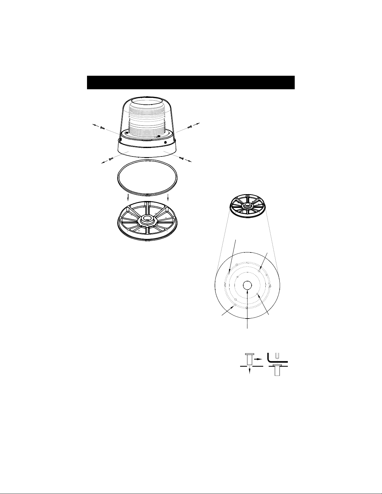
200A Mounting
Gasket
Remove the 4 screws in the
side of the Aluminum housing
and slide the plastic base out
Plastic Mounting Base
1 Remove the four screws in the side
of the aluminum housing
2 Slide the plastic base out of the
aluminum case
Do not to damage the gasket
0 189" Diameter
on 1 75" Radius
2 @ 180°
1" NPT THREADED
PIPE MOUNT
0 261" Diameter
on 3 125" Radius
3 @ 120°
101-AP
0 196" Diameter
on 2 975" Radius
3 @ 120°
0 264" Diameter
on 2 5" Radius
2 @ 180°
6 Insert the rubber well nuts into the mounting holes so the
wider lip rests on the mounting surface
7 Route the wires through the center hole and install the screws
through the base, into the well nuts, and tighten until snug
8 Place the light on the base and reinstall the four screws
3 Determine which knockouts on the base will
work best for your application and clear them
using a punch or other appropriate tool
4 Using the plastic mounting base as a
template, mark the appropriate holes on the
mounting surface
5 Drill a 3/8" hole in the marked locations
Then, if applicable, drill a 3/8" hole for the
wires in the center of the outer holes
CAUTION: Take care no o drill hrough
he headliner of he vehicle below.

-2-
Magnet Mounting
If you are ounting the light on the roof of your vehicle, take extre e care to ensure
that the agnet is fir ly seated on your roof, and that the pull of the agnet is
sufficient to secure the light in place. As the co position of the etal in the roofs of
different vehicles ay vary, as well as the contour, texture, and/or condition, the
anufacturer cannot guarantee the ability of the light to re ain in place upon a oving
vehicle. It is the sole responsibility of the owner to ensure the warning light is secure.
WARNING!!!! Care should be taken when positioning any warning light on the roof,
dash, or instrument panel of the vehicle, so that the light and/or cord
does not interfere with the proper operation of any airbags! Failure to
heed this warning may result in serious or fatal injury
CAUTION: Please be sure to check that your cigarette plug outlet is properly fused
Testing the light before this fuse is properly installed will void the warranty on
the light.
If the light fails to work when the plug is inserted into the cigarette plug socket, twist the
plug a few times to remove any ash or other deposits which might be preventing a
good contact from being made If the problem persists, check for a fuse inside of the
plug itself If present, remove the fuse from the circuit, check to see if it has blown, and
clean the lighter socket and contact surfaces Reconnect the fuse and test the light
again
200S, 240, and 266 Surface Mounting
1 Decide which holes you will be using to mount your light Models without a flange will
have knockouts inside the base that can be used To locate them, carefully remove
either the clamp ring or the screws near the base of the lens and lift off the lens Use a
punch or drill to remove the knock-outs present
2 Using the gasket as a template, mark the appropriate mounting holes Mark a center
hole if you will be running your wires through the mounting surface
3 In the marked locations, drill appropriately
sized holes for the hardware you are using
4 If using well nuts, push them through the
mounting holes until the bottom side of
the wider lip rests on the surface of the
vehicle
5 Install the wire grommet on the center hole (if applicable)
6 Route the wires through the center hole (if applicable) and secure
the light with included hardware
For NPT pipe, mount the light using the threaded entrance hole in the base of the light, then
skip to the Wiring Instructions
Pipe Mounting
WELL NUT STANDARD NUT
-3-
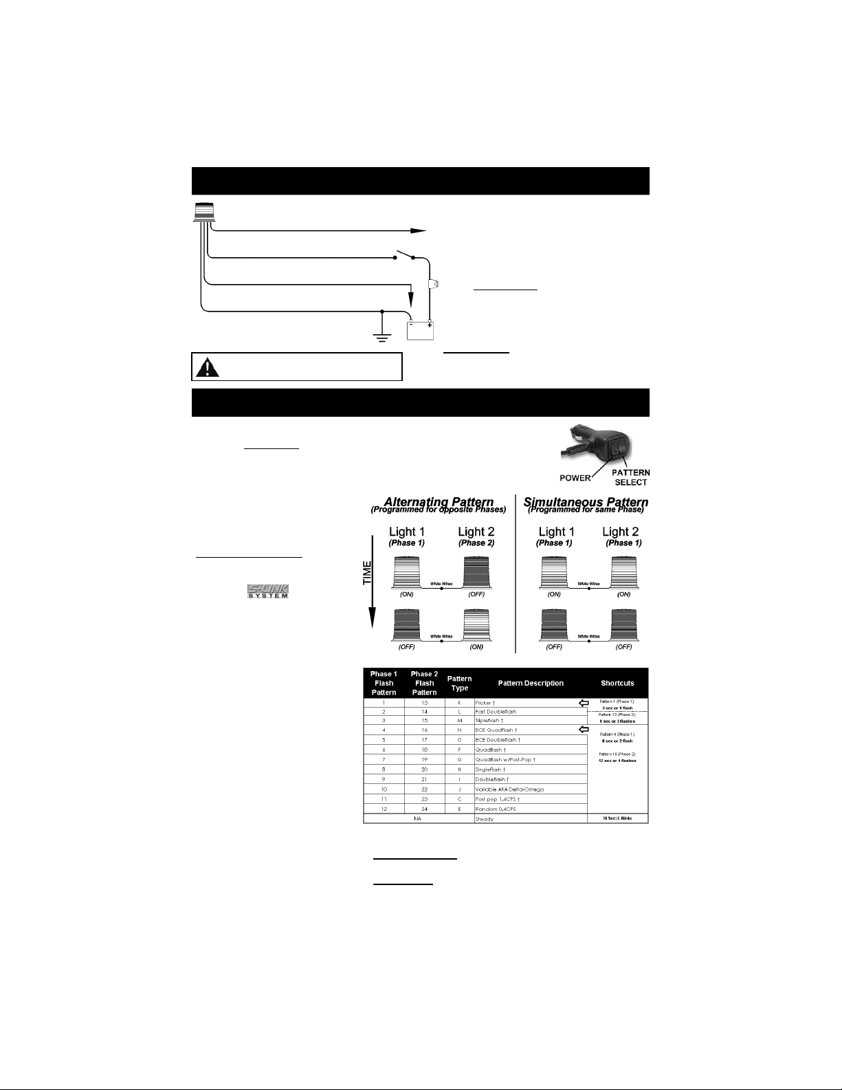
To change patterns, press the pattern select button on the cig plug, or
touch the green wire to ground on hard-wired models
If applicable, after the pattern has been set, tape or place a wirenut
over the end of the green wire to prevent it from coming into contact
with ground
Pattern Progra ing
SYNCHRONIZATION
(Hard wire only)
You can synchronize up to six
lights with compatibility.
DO NOT CONNECT WHITE
WIRES UNTIL PROGRAMMING
HAS BEEN COMPLETED FOR
ALL LIGHTS!!
1 Program the first unit
2 Program the second light with
the same Pattern Type
Lights with the SAME phase
flash together (simultaneous)
Lights with DIFFERENT
phases flash opposite one
another (alternate)
3 After programming all lights,
cap off the green wires and
with the power off, connect
the white wires together
4 Test lights by applying power
to all of them at the same
time
Wiring Instructions
CAUTION:
All of our DC powered warning lights are
polarity sensitive These lights are
polarity protected only if the appropriate
fuse is used All wires connected to the
positive terminal of the battery should be
fused at the battery for their rated load
Tes ing he ligh before his fuse is
properly ins alled will void he
warran y on he ligh .
RED: Power - Connect to +12-24VDC through
your switch and a 5A fuse
WHITE: Synchronization - AFTER setting the flash
patterns, connect the white wires from
synchronized lights together Cap off if not used
GREEN: Pattern Select - Touch & Release to ground
BLACK: Ground - Connect to the
negative terminal of the battery
or a good chassis ground
Cig Plug Models : +12VDC only
Please Note: If your light contains a
PURPLE wire, it is a dead wire that is
not used and can be cut short.
† - SAE J845 approved patterns when properly configured
Pattern Shortcuts: Hold Green wire to ground for
indicated ti e.
Steady Burn: Not in Pattern Cycle. Hold Green wire to
ground for 18 seconds (light will flash 5
ti es).
This manual suits for next models
10
Table of contents
Other Star Headlight & Lantern Security System manuals


