Pulsar AWZ 710 PN-K User manual

1
AWZ 710
PN-K
v.1.0
Foot-operated emergency button.
EN
Edition: 3 from the 9
th
September 2010
Supercedes edition: 2 from the 10
th
July 2009
1. Techn cal descr pt on.
1.1 General descr pt on.
The foot-operated button is used for transmitting signal indicating alarm situation occurrence calling help (e.g. to
the alarm central monitoring transmitter controller). The foot-operated button converts the signal of pressed button into a
change of the alarm status. The PN-K foot-operated button is equipped with numerous programming functions which
enable the flexible adjustment to requirements of a particular installation. The pushbutton detector is made according to
the optical technology. The output signal is presented in a form of shorting/opening contacts of reed relay switch
(noiselessly). The atni-sabotage contact is based on a microswitch with gold-covered contacts the PCB surface has been
covered with lacquer to provide protection against damp and dust. The button has got a compact casing and is equipped
with rubber anti-slip feet.
Information about types:
Model Descr pt on
AWZ 700
PN
Foot-operated emergency button.
AWZ 710
PN-K
Foot-operated emergency button programmable.
1.2 Descr pt on of elements and connectors on PCB.
Table 1.
Nr
[rys.1] Element descr pt on
[1] Anti-sabotage switch connector
[2] Wire holder
[3] PROG/RESET button
[4] Supply connector and button output
[5] LED (red) operations signaling (programming)
Table 2.
[1] [4] Connectors descr pt ons
TAMP NC anti-sabotage switch output
12V
GND Supply output DC (12V= +U GND)
RST Button reset output
C
NO NC alarm transmitter output

2
Fig. 1. The view of PCB.
1.3 Techn cal parameters:
- electric al parameters (tab.3)
- mechanical parameters (tab.4)
Table 3.
Supply voltage 11V÷14V/DC (-/+5%)
Current consumpt on 17mA/30mA (R=NO/R=NC)
ALARM transm tter 0 5A@30Vdc/50Vac max.
ALARM transm tter contacts C/NC
ALARM transm tter operat ons mode monostable (210s max.) bistable or latch
programming function
RST output (RESET) control 0V (GND) impulse time min 1s.
TMP output C/NC 1A@30Vdc/50Vac max.
Opt cal nd cat on
- LED (red)
- alarm status: permanently illuminated
- countdown of abort time or supply restart: flashes
- programming: go to programming procedure
Operat on cond t ons II environment class -10°C ÷40°C
Table 4.
Cas ng metal RAL 9003 IP20
D mens ons 120 x 75 x 36 (WxLxH)
F xat on No fixation
Connectors Ф0 41÷1 63 (AWG 26-14)
Net/Gross we ght 0 18kg/0 22kg
2. Installat on.
2.1 Requ rements.
The foot-operated button shall be mounted by the qualified installer having appropriate (required and necessary
for a given country) permissions and qualifications for connecting (operating) low-voltage installations. The device shall
be mounted in closed rooms according to the environment class II of the normal air humidity (RH=30%-90% max.
without condensation) and the temperature within the range from -10°C to +40°C.
2.2 Installat on procedure.
1. Perform complete installation wiring and choose button location.
2. Open the button unscrewing two side screws (that are a button hinge).
3. Connect wire to the button through a rubber hole and block in the holder (fig.1).
4. Connect DC supply to 12V, GND holders maintaining polarization.
5. Connect wires to ALARM (C/NO), TAMP outputs and RTS button inputs.

3
6. Switch on DC supply (red LED shall flashes; signalization of operation start)
7. Program the button mode (see programming procedure).
8. Screw the button using two screws.
9. Perform functional tests.
3. Opt cal s gnal zat on.
The button is equipped with the LED that indicates operations or programming status.
• LED- red:
- alarm status: permanently illuminated
- countdown of abort time or supply restart: flashes
- programming: go to programming procedure
4. Programm ng.
4.1. Programm ng descr pt on.
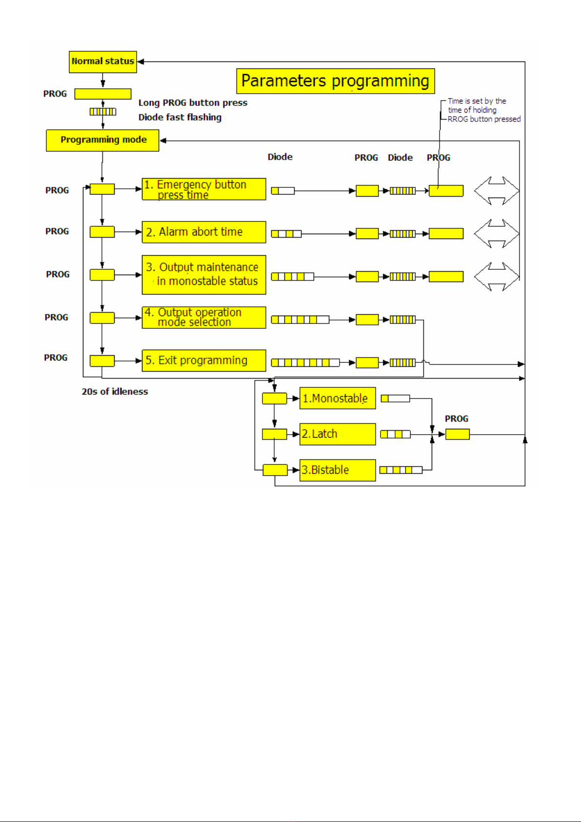
Enter programming mode: press PROG/RESET button for about 5 sec. The diode starts flashing fast in this
mode short button press selects parameters we want to edit the number of active parameter is signalized by LED
flashes. To confirm program choice press PROG/RESET button for about 3 sec the choice is confirmed by short flashes.
Not ce!
If the button s not pressed n 20s, dev ce w ll ex t the programm ng mode w thout sav ng the sett ngs.
Programs:
1. Emergency button press time.
2. Alarm abort time.
3. Back-up time in the monostable mode.
4. Output operation mode selection.
5. Exit programming mode.
Program 1: emergency button press t me.
In the main menu (LED x 1) press PROG/RESET button for about 3s. Then press and hold PROG button for a
desired period of time (LED = flashes). Button press time is the time of parameter that is being programmed. After button
release time length is saved in the device memory and the device returns to the “main menu”.
Factory presets: 1s.
Program 2: alarm abort t me.
In the main menu (LED x 2) press PROG/RESET button for about 3s. Then press and hold PROG button for a
desired period of time (LED = flashes). Button press time is the time of parameter that is being programmed. After button
release time length is saved in the device memory and the device returns to the “main menu”.
Alarm abort time is the time that is counted down (LED = flashes) after the first button press if the time is not
equal to 0s. Alarm action does not occur when during the abort time the button is pressed again.
Factory presets: 0s.
Program 3: back-up t me n the monostable mode.
In the main menu (LED x 3) press PROG/RESET button for about 3s. Then press and hold PROG button for a
desired period of time (LED = flashes). Button pressed time is the time of parameter that is programmed. After button
release time length is saved in the device memory and the device returns to the “main menu”.
Factory presets: 2s.
Program 4: output operat on mode select on.
In the main menu (LED x 4) press PROG/RESET button for about 3s. Then press the PROG button for a short
period of time and the diode will indicate loop selection. (LE= 1 2 3: operation mode).
- monostable (LED x1) = active output during the time set in 3 program
- latch (LED x2) = active output till reset time via RTS inut or PROG/RESET button
- b stable (LED x3) = output changes status after every button press
In order to confirm the mode press and hold the PROG button for about 3s or wait 20s. (20s idle state).
Factory presets: monostable mode.
Program 5: ex t programm ng mode.
In the main menu (LED x 5) press PROG button for about 3s. The button quits the programming mode and saves
the settings.

4
4.2. Programm ng d agram.
5. Serv ce and operat on.
It is not necessary to perform any special maintenance operations but if the power supply interior is significantly
dusty it shall be vacuum-cleaned by the compressed air.

5
WEEE MARK
The waste electr c and electron c equ pment shall not be d scarded together w th common home waste mater als.
Accord ng to the WEEE d rect ve val d n EU, part cular methods of ut l zat on shall be appl ed for the waste electr c
and electron c equ pment.
Pulsar K.Bogusz Sp.j.
Siedlec 150 32-744 Łapczyca Poland
Tel. (+48) 14-610-19-40 Fax. (+48) 14-610-19-50
e-mail: [email protected] sa[email protected]l
http:// www.pulsar.pl
GENERAL WARRANTY CONDITIONS
1. Pulsar K. Bogusz Sp.j. (manufacturer) grants a two-year quality warranty for the equipment starting from the date of purchase
placed on the purchase order.
2. Should such purchase order be missing when the claim is submitted the three-year guarantee period is counted from the date
of the manufacturing of the device.
3. The warranty includes free-of-charge repairing or replacing with a functional equivalent (the selection is made by the
manufacturer) of the malfunctioning device due to reasons attributable to the manufacturer including manufacturing and
material defects unless such defects have been reported beyond the warranty period (item 1 and 2).
4. The equipment subject to warranty is to be brought to the place where it was purchased or directly to the main office of the
manufacturer.
5. The warranty applies to complete equipment including the type of defect specified in writing using a properly filled warranty
claim.
6. Should the claim be accepted the manufacturer is obliged to render warranty repairs as soon as possible however not later
that within 14 days from the delivering of the equipment to the service centre of the manufacturer.
7. The repair period mentioned in item 5 may be prolonged if there is no technical capability to carry out the repairs and in the
case that the equipment has been accepted conditionally due to the failing of the warranty terms by the claimant.
8. All the services rendered by force of the warranty are carried out at the service centre of the manufacturer exclusively.
9. The warranty does not cover the defects of the equipment resulting from:
- reasons beyond the manufacturer's control
- mechanical damage
- improper storage and transport
- use that violates the operation manual or equipment application
- random events including lightning discharges failures of power networks fire flooding high temperatures and chemical
agents
- improper installation and configuration (at variance with the rules set forth in the manual)
10. Each confirmation of structural modifications or repairs carried out beyond the service centre of the manufacturer or any
modification of serial numbers or warranty labels results in the loss of the rights resulting from the warranty.
11. The liability of the manufacturer towards the buyer is limited to the value of the equipment determined according to the
wholesale prices suggested by the manufacturer on the day of purchase.
12. The manufacturer shall not be responsible for the defects that resulted from the damaging malfunctioning or inability to
operate the equipment particularly if such defects are the result of failing to abide by the recommendations and requirements
contained in the manual or the use of the equipment.
Table of contents
Other Pulsar Security System manuals
Popular Security System manuals by other brands

Simon
Simon Simon installation instructions

Concept Smoke Screen
Concept Smoke Screen Sentinel S70 Installation and operation manual

Cocoon
Cocoon HE180040 instruction manual

Honeywell
Honeywell ADEMCO LYNXR Series Installation and setup guide

SkyLink
SkyLink SC-100 Guide User instructions

Velleman
Velleman CCTVPROMT1 Quick installation guide