StarCharge DH-AC0070XG70 Instruction Manual

7/11kW AC EVSE
Installation & User Manual
Wanbang Digital Energy Co., Ltd.
Identifying symbols
Instruction Manual Wanbang Digital Energy Co., Ltd. 1
Rev. B-004
Identifying symbols
Symbols Meaning
“Warning”, which indicates a hazard
Pay
attention to personal injuries or death caused by operation steps, practice or
incorrect implementation. The operation after the "warning" sign can only be
performed when the conditions are fully understood and satisfied.
“Caution”, which indicates a hazard.
Pay attention to the damaged or destroyed product caused by the operation
steps, experiments or incorrect execution. Only after fully understanding and
satisfying the indicated conditions, the operation after the “caution” mark can be
performed.
"Hint", which indicates skill or useful information.
Skills and useful information are marked as “Hint”. It does not contain information
that warns of dangerous or harmful features.
“Garbage disposal”, which indicates electrical and electronic waste.
This symbol is located on the product, in the instruction manual or on the
packaging, indicating that the electrical and electronic equipment and its
accessories should be disposed separately from ordinary household waste.
Materials can b
e reused based on their markings. By reusing old equipment,
materials and other forms of reuse, you can make a significant contribution to the
environment.

Content
Instruction Manual Wanbang Digital Energy Co., Ltd. 2
Rev. B-004
Content
Identifying symbols ................................................................................................................................. 1
1. Key Information ............................................................................................................................................... 4
1.1 Safety Instruction ...................................................................................................................................... 4
1.2 Specified Use ............................................................................................................................................ 5
1.3 About this manual ..................................................................................................................................... 5
2. Product Overview ............................................................................................................................................ 6
2.1 Product Features ...................................................................................................................................... 6
2.2 Product Functions .................................................................................................................................... 6
2.3 Technical Characteristics ......................................................................................................................... 7
3. Operation Instruction ...................................................................................................................................... 8
3.1 Appearance Introduction ......................................................................................................................... 8
3.2 storage of charging cable and connector ........................................................................................... 10
3.3 Start-up charger .......................................................................................................................................11
3.4 End charger ..............................................................................................................................................11
3.5 Instructions to User .................................................................................................................................11
3.6 Indicator Description .............................................................................................................................. 12
3.7 Emergency button .................................................................................................................................. 12
4. Troubleshooting ............................................................................................................................................. 14
5. Routine Maintenance.................................................................................................................................... 15
5.1 Power distribution system ..................................................................................................................... 15
5.2 Wiring System ......................................................................................................................................... 15
5.2.1 Cable ............................................................................................................................................. 15
5.3 Circuit Components ................................................................................................................................ 15
5.3.1 Components ................................................................................................................................. 15
5.4 Auxiliary System ..................................................................................................................................... 16
5.4.1 Indicator Lights .................................................................................................................................... 16
5.5 Electrical Ground System ...................................................................................................................... 16
5.6 Appearance ............................................................................................................................................. 16
5.7 Maintenance Period ............................................................................................................................... 17
6. Customer Service.......................................................................................................................................... 18
6.1 Preparation .............................................................................................................................................. 18
6.2 Contact Information ................................................................................................................................ 18
A. Installation Instruction ................................................................................................................................... 19
A.1 Installation Requirements ..................................................................................................................... 19
A.2 Power Supply Requirements ................................................................................................................ 23
A.3 Environmental Requirements ............................................................................................................... 24
A.4 Wiring Requirements ............................................................................................................................. 24

Content
Instruction Manual Wanbang Digital Energy Co., Ltd. 3
Rev. B-004
A.5 Product Installation ................................................................................................................................ 24
A.5.1 Wall-mounted charger ........................................................................................................................ 25
A.5.2 Pole-mounted charger ....................................................................................................................... 30
B. Appendix......................................................................................................................................................... 34
C. Warranty Card ....................................................................................................................................... 35
C.1 Warranty Terms and Conditions .......................................................................................................... 35
C.2 Information Registration ........................................................................................................................ 36
D. Equipment Accessories ........................................................................................................................ 37
D.1 Equipment Accessories List ................................................................................................................. 37
Key Information
Instruction Manual Wanbang Digital Energy Co., Ltd. 4
Rev. B-004
1. Key Information
1.1 Safety Instruction
Symbol Content
Failure to follow safety instructions can result in death, injury, and equipment damage.
Refuse to bear any claims arising from this.
Electrical hazard
Only
trained, qualified and authorized electrical professionals are responsible for
installation.
The first time to commission and maintain the charger, it should comply with existing
standards and installation regulations when performing the aforementioned
operations. See chapter "A Installation Instructions" for details.
Electrical hazard / fire hazard
Must regularly check the charging connector (including cable) in charger for
damage and check whether the case is damaged (visual inspection).
If the charger is damaged, it must be turned off and replaced immediately.
Do not perform the charger maintenance work without authorization. Only the
manufacturer can perform the operation (replace the charger).
Do not modify or modify the charger.
Never remove
signs such as safety symbols, warnings, nameplates, signs or
pipeline markings.
No extension cable shall be used when connecting the electric vehicle to the electric
vehicle power supply device.
Only connect electric vehicles or their charging equipment. Do not connect other
loads (power tools, etc.).
Hold the connector when pulling the charging connector, and do not pull the cable.
Do not bend, squeeze or tilt the charging connector so that it is mechanically
damaged.
Do not touch the heat source, dirt or water on the contact surface.
Some vehicles may generate toxic or explosive gases in the indoor area during
charging, so an external ventilation system must be provided.
When using an integrated charger to charge your electric car, please read the
vehicle's tips and instructions carefully.
CAUTION
Damage hazard.

Key Information
Instruction Manual Wanbang Digital Energy Co., Ltd. 5
Rev. B-004
Never use spray water to clean the charging point (Hose for garden watering, high
pressure cleaners, etc)
The adaptors or conversion adapters and extension cords are not allowed to be
used.
Cord extension sets are not allowed to be used.
1.2 Specified Use
This product is AC charger that can charge electric powered vehicles (for example, an electric car)
in indoor and outdoor areas.
When installing and connecting the charger, follow the regulations of each country.
The intended use of the equipment includes, in all cases, the environmental conditions established
for the equipment.
The storage of charger should be met the following requirements:
Before the equipment installation, the charger with components should be stored in the indoor
dry and ventilated place. The warehouses’ temperature is between -40
℃
and
﹢
85
℃
, the
monthly average relative humidity is not exceeded 90%, and there is no corrosive or explosive
gas. During the storage, please avoid rain, exposure, condensation and frost.
After the equipment installed, the charger shell should be kept sealed to avoid raining and
soaking.
The equipment is developed, produced, inspected and filed according to relevant safety standards.
Therefore, if the instructions and safety technical instructions for the intended use are observed, the
product will not cause damage to property or endanger the health of the person under normal
circumstances.
The instructions contained in this manual must be strictly observed, otherwise there may be a safety
hazard or the device may fail. Although this manual describes the relevant safety instructions, it is
important to pay attention to the safety regulations and accident prevention regulations when the
charging equipment is used.
Due to technical and legal restrictions, it is not possible to supply all models to all countries and
regions.
Equipment for locations with non-restricted access.
1.3 About this manual
This manual applies to the device type: AC charger
This manual is for the following people:
End customer (AC charger user).
Debugging and service technicians.

Product Overview
Instruction Manual Wanbang Digital Energy Co., Ltd. 6
Rev. B-004
2. Product Overview
2.1 Product Features
Detailed description of product performance
Model
DH-AC0070XG70
(Case C: plug, type2)
DH-AC0070XG71
(Case B: socket, type2)
DH-AC0110XG70
(Case C: plug, type2)
DH-AC0110XG71
(Case B: socket, type2)
Rated Power 7 kW 11 kW
Dimension 282 mm×409 mm×148 mm
Cable length 5 m
Weight approx. 4.4 kg approx. 5.7 kg
Installation Wall-mounted / Pole-mounted
Technical
Parameters
Input Voltage: AC230±10% Input Voltage: AC400±10%
Input Mode
:
Single-phase, L1+N+PE
Input Mode
:
Three-phase, L1+L2+L3+N+PE
Output Current: 32A max. Output Current: 16A max.
Frequency: 50 Hz/60 Hz
Charging modes: Mode 3
Protection against electric shock: Class I
Overvoltage Category: OVC III
Output Voltage: AC230±10% Output Voltage:AC400±10%
IP and IK rating: IP55(Case C),IP54(Case B),IK10
Material: PC
Codes and
standards IEC 61851-1:2017
;
IEC 61851-21-2:2018
2.2 Product Functions
1
)
Charging function
:
During the charging process, the charger can identify the connection state between
the charger and the vehicle end, and according to this state, the vehicle can be guided to perform safe
charging. The vehicle can control the start and stop of charging.

Product Overview
Instruction Manual Wanbang Digital Energy Co., Ltd. 7
Rev. B-004
2
)
The charger controller has the functions of measurement, control and protection for the charger.
3
)
With lighting protection, overload protection, short circuit protection, leakage protection, over voltage
protection, under voltage protection and grounding detection.
4
)
Charger supports OCPP 1.6J communication protocol, and the charger can be linked to the data
service platform and management platform (Cloud platform) of OCPP 1.6J.
5
)
The charger can keep normal working status when used in outdoor environment (Protection level is
IP55(Case C),IP54(Case B), IK10).
2.3 Technical Characteristics
1
)
Charging method:
Use the mobile APP to scan the charging QR code for charging.
Swipe the RFID card to start charging.
2
)
Have perfect protection functions.
3
)
Suitable for all vehicles complying with IEC 62196-2.
4
)
Output power configuration
:
support output power configurable (Maximum output current set by
DIP switch, single-phase 0A-32A, three-phase 0A-16A).
Operation Instruction
Instruction Manual Wanbang Digital Energy Co., Ltd. 8
Rev. B-004
3. Operation Instruction
3.1 Appearance Introduction
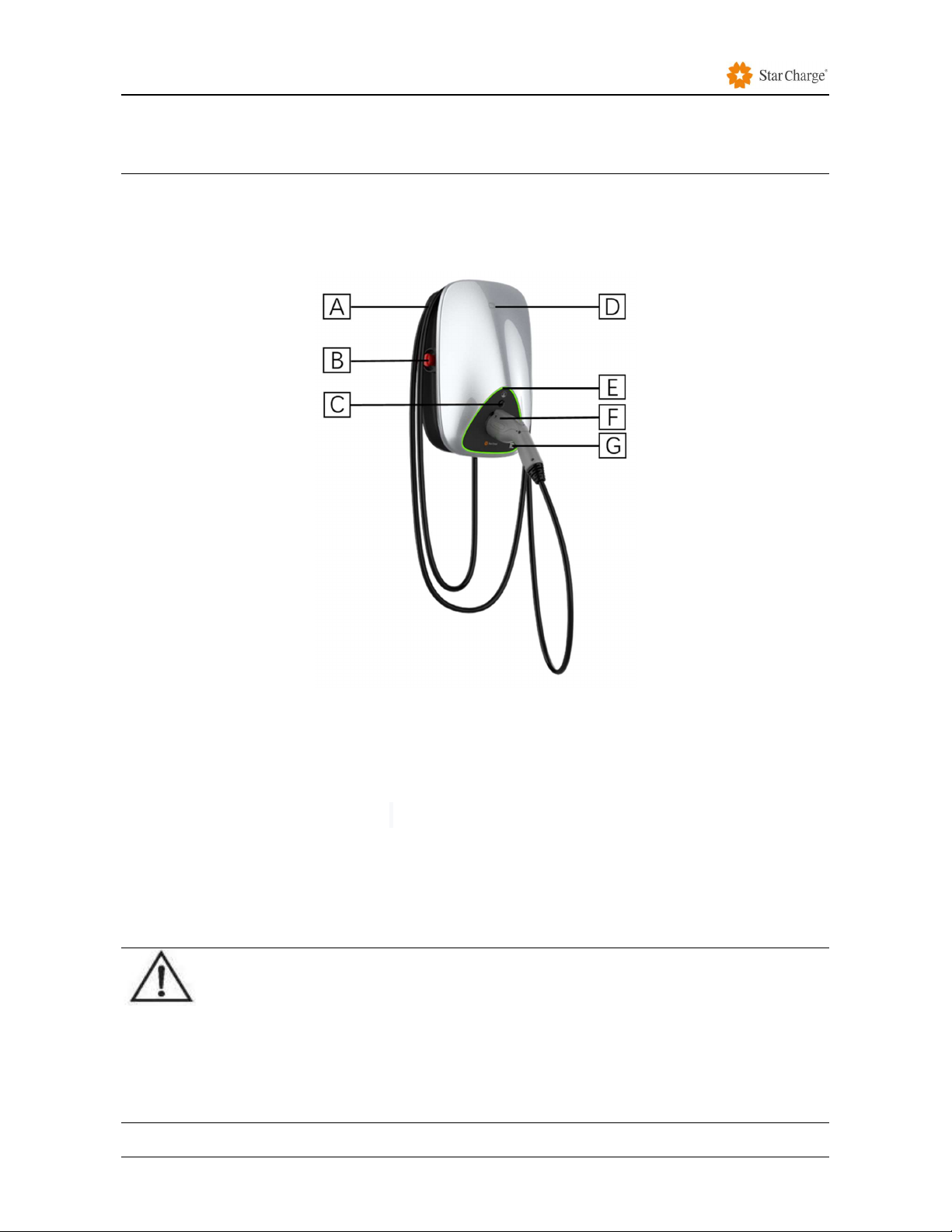
Case C
Figure 3-3 Appearance of the wall-mounted (Subject to the actual product)
[A]——Cable winding trough
[B]——Emergency stop: press the button to stop the device running when the device is running
abnormally
[C]——Charge plug unlock button: press the button to unlock the charging plug
[D]——Authenticate to start by swiping RFID card
[E]——LED status indicator, standby mode constant green
[F]——Position of the charging connector
[G]——Authenticate to start charging by scanning QR code
The appearance is subject to the actual product.
When charger is not used, the charging cable should be rolled up and put back into the cable
winding trough in position [A] as indicated in figure 3-3, and the charging connector should be
inserted into the designated position [F] for safe storage.

Operation Instruction
Instruction Manual Wanbang Digital Energy Co., Ltd. 9
Rev. B-004
Figure 3-4 Appearance of the pole-mounted (Subject to the actual product)
[A]——Optional cable winding trough
[B]——Emergency stop: press the button to stop the device running when the device is running
abnormally
[C]——Charge plug unlock button: press the button to unlock the charging plug
[D]——Authenticate to start by swiping RFID card
[E]——LED status indicator, standby mode constant green.
[F]——Position of the charging connector
[G]——Authenticate to start charging by scanning QR code
[H]——Mounting Column
[I]——Cable winding bracket
The appearance is subject to the actual product.
When charger is not used, the charging cable should be rolled up and put back into the cable
winding trough in position [A] or placed on the bracket [I] of the stand as indicated in figure 3-4, and
the charging connector should be inserted into the designated position [F] for safe storage.
Operation Instruction
Instruction Manual Wanbang Digital Energy Co., Ltd. 10
Rev. B-004
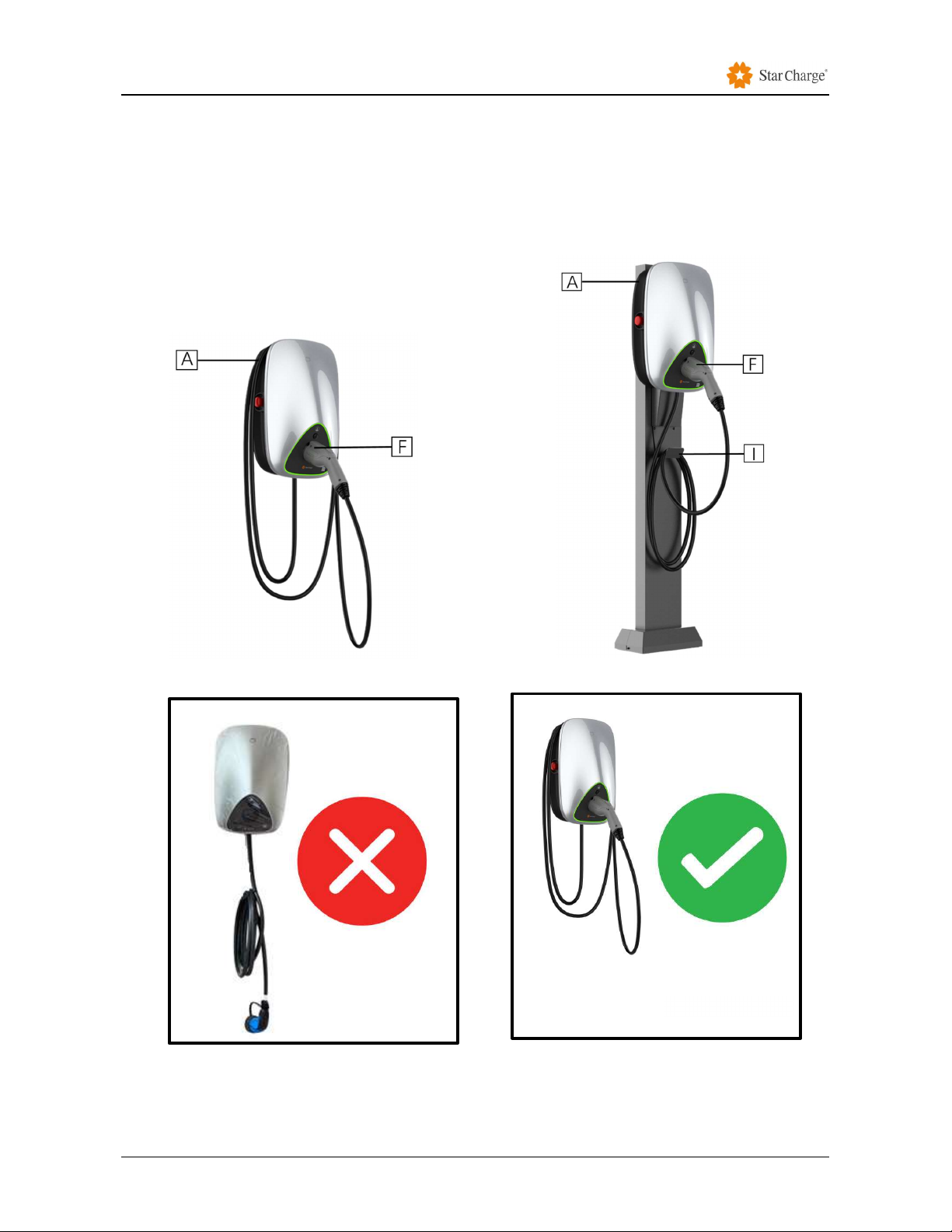
3.2 storage of charging cable and connector
When charger is not used, the charging cable should be rolled up and put back into the cable winding
trough in position [A] in figure 3-5 or placed on the bracket [I] of the stand as indicated in Figure 3-6,and
the charging connector should be inserted into the designated position [F] for safe storage
Wall Mounted Pole Mounted
Figure 3-5 Proper storage of cable &connector Figure3-6 Proper storage of cable &connector
Figure 3-7: Example of Cable & Connector not proper stored (Figure 3-7a), versus proper storage
(Figure 3-7b)
Figure 3-7b
Figure 3-7a

Operation Instruction
Instruction Manual Wanbang Digital Energy Co., Ltd. 11
Rev. B-004
3.3 Start-up charger
Precondition
The charging connector is not inserted in the vehicle.
The charger is ready for operation (the LED status is constant green).
The steps
Step 1 Insert the charging connector into the vehicle and confirm that it is connected properly, the blue
LED lights up means the charger is in connection status.
Step 2 (Option 1) Use the mobile APP of the binding platform to scan the charging QR code for
charging.
Step 3 (Option 2) Or using the RFID card to place in the card swiping area until the LED indicator
continues to flash, the frequency of flashing is 4 times in 1s. If the start-up by card swiping is not
successful due to network reasons, please re-start the card swiping process.
Step 4 When the brightness of the blue LED changes gradually, it means that the charging process has
started.
--End
3.4 End charger
The steps
Step 1 After swiping card or using the App provided by the Charge Point Operator to end charging
process, the charging connector can be pulled out from the vehicle to completely to end the whole
charging process
Step 2 Put back the charging cable into the bracket provided with the charger and properly store the
cable as shown in item 3.2 of this manual.
--End
3.5 Instructions to User
The below instructions and safety precautions shall be installed and placed right beside the charging
station by the Charge Point Operator in a manner that is sturdy and visible to the user.
1. Basic Instructions to use the Charger:
Start Procedure
1) Check if the power is “ON” (Green light is “ON”).
2) Plug-in the charging cable to the vehicle (The light will turn Blue).
3) Tap the RFID Card or Scan the QR code via the provided Mobile App by the Charge Point
Operator.
4) Once the charging begins, the blue light will start breathing.
Note: Refer to the light status to make sure that the charger is charging. Please refer to item 3.6 in this
manual

Operation Instruction
Instruction Manual Wanbang Digital Energy Co., Ltd. 12
Rev. B-004
Stop Procedure
1) If the car is fully charged the charger will stop automatically.
2) To stop the charging manually, tap the RFID card or tap the “End Charging” on the Mobile
App provided by the Charge Point Operator.
3) Unlock the charging cable from the vehicle.
4) Remove the charging cable.
5) Cover or plug-in the cable into the charger.
6) Roll up the charger cable to original position.
2. Safety Precautions
1) Do refrain from using Charger in thundery weather if Charger is located outdoors.
2) In case of emergency, press the red emergency stop button to deactivate the charging process
3) Check that the housing of the charging station is intact and hasn’t suffered any obvious
mechanical damage or deformation
4) Check that the charging station is securely fastened to the wall or on the pole
5) Check that nothing is obstructing the connection of the charging cable to the charger socket
6) Do not use brute force to pull out the mechanically locked charging connector out of the charger
socket or the Electric Vehicle socket.
3.6 Indicator Description
Basic/Smart
NO. Charger Status LED indicator color LED Effect
1 Standby Green Constant
2 Charging Blue Changes gradually
3 Fault Red Constant
4 Vehicle end S2
disconnected Blue Pulsate (1Hz)
5 Charging current
<
1A for 10 minutes Blue Constant
3.7 Emergency button
In the event of an emergency, the user should depress the emergency stop button on the
charger. Once activated, the emergency stop button will cut off the power supply of the charger
from the relay coil and disconnect the hardware circuit board. At the same time, the backend
charging management system located in Singapore at AWS data center will be alerted that the
emergency stop button has been depressed and this charger will then be immediately

Operation Instruction
Instruction Manual Wanbang Digital Energy Co., Ltd. 13
Rev. B-004
deactivated from the system. A deactivated charger will not be able to be used for charging until
it is reactivated on the charging management system by customer service engineer.

Troubleshooting
Instruction Manual Wanbang Digital Energy Co., Ltd. 14
Rev. B-004
4. Troubleshooting
Fault Possible causes and solutions
Power LED is off No power supply
Damaged, please contact your service partners.
Unable to start the
charging process
Did not insert the connector into the vehicle properly:
Pull out and plug in again.
Did not execute charging steps correctly:
Follow the instructions in the 3.2 Start-
up charger process
section.
The connector is dirty or damaged around the security area:
Clean or replace the charging connector.
The vehicle is not fully
charged or the
charging time
increased
Due to extreme high temperature of the vehicle or the integrated
charger the current drops:
Visually check if the plug device is smudgy, worn out
or
damaged.
If necessary, please contact your service partners.
Due to the external control device (power supply equipment, PV
equipment, or others), the charging cannot be completed.
Fault status:
red LED lights on
Fault
Check all possible cause for failure in the first place (*).
Make sure that the emergency stop button pressed.
Cut off the power supply of the charger, pull out the charging
connector of the vehicle and switch the po
wer supply back
on.
Damage
Please contact your service partners.
(*) Possible causes for failure
(
fault status, red LED light on):
In principle, the fault should be solved by pulling the charging connector out of the vehicle
:
The emergency stop button is pressed to cause a power failure.
Please contact the administrator for hardware recovery.
Ungrounded, leaked, and no charging station ID.
Please contact your service partner to maintain the equipment.

Routine Maintenance
Instruction Manual Wanbang Digital Energy Co., Ltd. 15
Rev. B-004
5. Routine Maintenance
The following routine maintenance items are for reference only. Please refer to the relevant standards
and operation instructions for operation.
5.1 Power distribution system
Power on and off steps of the distribution box.
1
)
Check if the supply voltage is normal.
2
)
Power on: first turn on the main switch of the distribution box and then the branch circuit switch.
3
)
Power off: first turn off the branch circuit switch, and then turn off the main switch of the distribution
box.
5.2 Wiring System
5.2.1 Cable
Weekly routine inspection: check cable for heating and breakage.
Monthly routine inspection: check cable for heating, breakage, whether the cable is subjected to
external pull force, Fixed securely.
Annual routine inspection: check whether the cable is connected closely to the switch, whether the
grounding is reliable, whether the cable is hot or damaged, and whether the insulation resistance of
the cable is in accordance with the regulations. The sealing measures of cable into the box are intact,
hole sealing is tight.
5.3 Circuit Components
5.3.1 Components
Weekly routine inspection: the emergency stop button is working normally. After pressing the
emergency stop button and that it is confirmed the control circuit is disconnected, check whether all
operation indicator lights and buzzers are working normally and if the charging connector's fixed
clasp is damaged or the connection is abnormal.
Quarterly routine inspection: check whether the circuit components are fixed firmly and if there is
a phenomenon of fire burning at the connection of the components. If any abnormality is found,
please replace the components as fast as possible.
Annual routine inspection: use the brush and vacuum cleaner to remove the dust from the box.
When cleaning, be careful to not blow dust into the components because it will cause a short circuit.

Routine Maintenance
Instruction Manual Wanbang Digital Energy Co., Ltd. 16
Rev. B-004
Complete inspection of all components and parts of the box. If any abnormality is found, please
replace the parts as fast as possible.
5.4 Auxiliary System
5.4.1 Indicator Lights
Monthly routine inspection: check if the indicator lights burning phenomenon are fixed firmly.
Annual inspection: make sure the wire and indicator light connections are tightly sealed and that
do not have corrosion and that all the accessories of the indicator lights are completed, fixed firmly
and have not burned out. Also check if the incoming insulation is in compliance with the regulations.
5.5 Electrical Ground System
Electrical grounding is very important in electrical operation. The safety of human and equipment
depends largely on the integrity and safety of grounding equipment. If the grounding equipment is not
solid, not reliable and does not conform to the standard requirements, it will inevitably lead to security
risks, and there is always the possibility of personal and equipment safety crisis.
Therefore, careful inspection and timely maintenance must be carried out to make the ground system
always operate in a safe state.
Weekly routine inspection: check if the grounding of the equipment is loose, lost or altered.
Observe carefully whether the grounding of the equipment is intact and if the anti-loosening device
is completed, damaged or removed.
Monthly routine inspection: make sure whether the connection of electrical grounding system is
not rusty, without oxidation or unstable; if it does, it will increase earthling resistance. Also check if
the grounding mark is completed or damaged. Check the device in the switch box for looseness,
corrosion, and rust.
Annual routine inspection: make sure the grounding wires and terminals are in good condition.
Use the multi-meter to detect whether the grounding resistance meets or exceeds the standard
grounding requirements.
5.6 Appearance
Monthly routine inspection, check whether there are stains in the appearance of the device, the overall
cleanliness of the whole device, timely modify the appearance.

Routine Maintenance
Instruction Manual Wanbang Digital Energy Co., Ltd. 17
Rev. B-004
5.7 Maintenance Period
Inspection item Every
month
Every
quarter
Every
half year Annual Treating method
Charging connector √ √ √ √ Check
Leakage switch
protection √ √ √ √ Check
Emergency stop
function check √ √ √ √ Test
Dust inspection of
control board √ √ √ √ Check and
Clear

Customer Service
Instruction Manual Wanbang Digital Energy Co., Ltd. 18
Rev. B-004
6. Customer Service
6.1 Preparation
If you have any questions or problems, please contact the company responsible for performing the
electrical installation.
Before contacting Customer Service:
Check the troubleshooting measures in the Troubleshooting section of this manual.
Check the troubleshooting measures in the Vehicle Manufacturer's manual.
Record the model and serial number of the device and send to the contact information in 6.2
below.
6.2 Contact Information
Company address: No.39, Longhui Road, Wujin High-tech zone, Changzhou, Jiangsu, China.
Website: www.starcharge.com
Company E-mail: starcharge@wanbangauto.com
Hotline in China: 400-828-0768

Installation Instruction
Instruction Manual Wanbang Digital Energy Co., Ltd. 19
Rev. B-004
A. Installation Instruction
A.1 Installation Requirements
The charger should not be installed close to dangerous locations such as water pipes, gas pipes,
and steam pipes.
The installation location should be convenient for charging. When laying the circuit, the wiring
length should be shortened, and the cable resistance energy consumption should be reduced.
The installation position of the vertical charging station should not be set at a place where the
terrain is low and water or dripping is easy. The installation should be vertical and the center of
gravity should not be too high to prevent tipping or tilting. It should not be placed in a place with
severe vibration or high temperature. The height of the charging column should be about 60cm
from the horizontal plane.
The wall-mounted charging station must be connected to the wall at least two points, and the tool
charging station cannot be removed. The wall should be installed to withstand the weight of the
charging station and its accessories and should not be tilted after installation. The wall and internal
lines should not be too close.
The indoor installation protection level is at least IP41, and the outdoor is at least IP44. It is
recommended that the charger be installed in an environment with a sunshade or umbrella; the
lighting and passage of the charger installation site must be guaranteed.
A certain space should be reserved for the installation of the charger, so that the engineering
personnel can open the back door of the equipment for inspection and maintenance. Ensure that
the ground wire is securely connected to the ground wire of the power supply system.
Case B is not recommended for public charging stations.
It shall recommended to install MCB, Shunt release and Type-B RCD with below two ways,
1.Choose a waterproof box and a Isolator switch that both complies with local regulations. First,
install MCB, Shunt release and Type-B RCD in the box, then, install the Isolator switch at front end
of the box, as shown in Figure A-3.
2.Install MCB, Shunt release and Type-B RCD to the front section inside the power distribution
cabinet(PDC) and an Isolator switch that complies with local regulations at front end of the MCB
and Type-B RCD.
The waterproof box shall have a minimum of IP44 degree rating.
The user needs to install MCB, shunt release and a type B residual current protector (B RCD) in
the front-end power distribution cabinet. Please see the table in D.1 Equipment Accessories List, in
which MCB, shunt release and type B RCD is included.
Power Rated voltage Rated current Tripping characteristics
7kW 230V 40A C
This manual suits for next models
3
Table of contents
Other StarCharge Batteries Charger manuals

Popular Batteries Charger manuals by other brands


Altronix
Altronix AL600ULX Series installation instructions

Humanscale
Humanscale Nova Assembly instructions

VOLTCRAFT
VOLTCRAFT VC-AL100N operating instructions

GYS
GYS STARTIUM 330E manual

Schumacher Electric
Schumacher Electric SP1 owner's manual

Classic Exhibits
Classic Exhibits InCharg MOD-1467 Setup instructions