Stark 61012 User manual

WARNING
To reduce the risk of injury, all operators and maintenance
personnel must read and understand these instructions before
operating,changing accessories,or performing maintenance
about this power equipment. All possible situations cannot be
covered in these instructions.Care must be exercised by
everyone using,maintaining or working near this equipment.
Reversible Plate Compactor
61012
Owner’s Manual
Questions? Problems? Please call our customer support:
(909) 628 4900 Mon-Fri 9am to 3pm PST

2
CONTENTS
Introduction………………………………………………………2
Applications………………………………………………………2
Structure …………………………………………………………2
Functions and controls …………………………………… ……3
Accessories………………………………………………………3
For safety operation ……………………………………………3
Hazards and risks……………………………………………… 4
Operation………………………………………………………4-9
Care and preventive maintenance……………………………9
Service………………………………………………………… 9
Specifications…………………………………………………10
Spare parts and service………………………………………10
Replacement parts list …………………………………… 10-15
INTRODUCTION
Thank you for yourselection of the power equipment.
Wehavetaken carein the design,manufacture and testing of
thisproduct. Should service or spare parts be required,
Prompl andefficientserviceis available fromourbranches.
General Safety Instructions for the Operation of
Power Equipment
Our factory's goal is to produce power equipment that helps the
operator work safely and efficiently. The most important safety
device for this or any tool is the operator.Care and good
judgement are the best protection against injury.All possible
hazards cannot be covered here, but we have tried to highlight
some of the important items individuals should look for and obey
Caution, Warning and Danger signs placed on equipment, and
displayed in the workplace. Operators should read and follow
safety instructions packed witheach product.
Learn how each machine works. Even if you have previously
usedsimilarmachines.carefullycheck outeach machinebefore
youuse it,Get the"feel"of itand knowits capabilities, limitations,
potential hazards, how it operates, and how it stops.We has no
dutyifpersondon’toperateas instructionsaid.
APPLICAIONS
Plate compactor is the machine that compactsthe groundand
it intends to make the surface smooth,by transmitting vibration
through vibrating plate,which power generated from single
motor in vibrator case This machine is suitable for making the
ground surface smooth, such as leveling the soil and beaching,
finishingtheasphalt paving.Applications asfollowings:
Trenchcompaction Earthworks
Road maintenance Landscaping
Brickpaving Drivewaytoppings
!Warningforincorrectapplicationandabuse
This machine is hard to move forward on a soil with much water
(especially clay soil). It is not suitable for such application. This
machine is difficult to level a ground include big stones due to
insufficient compacting force. Plate compactor is mainly applied
for compacting surface smooth and it is nor effective for jobs that
requires heavy compaction. In case of compacting ground
deeply into lower layer, it is recommended to use Tamping
Rammer ,Vibrator Compactor and Vibration Roller which
compacting force is rather effective. Please use this compactor
for compacting surface on soil, sediment, sand, beaching and
asphalt. It is not recommended for use this machine for any
other applications.
STRUCTURE
The upper part is made up of Power source, Handle, Belt Cover
and Guard hook which are fixedby
Engine base. The Engine base is fixed on Vibrating Plate by
ShockabsorbingRubber.Thelowerpertis madeup ofVibrating
plate and Vibrator until that has an Eccentric rotary shaft built in.
The power source is transmitted from the centrifugal clutch on
engine output shaft to the Eccentric rotaryshaft via V-belt.

3
PowerTransfer
Air-cooledSinglecylinderEngine isamountedaspower
source and Centrifugal Clutchis fixedonengine output
shaft.Petrol Engine(2 cycle,4cycle)and Diesel Gasoline
Engine can be mounted as option.CentrifugalClutch
engages byrunning up theengineand engine R.P.M. is
reduced to suitable number for compacting.The rotation
of engineistransmitted from V-pulleyintegrated with
ClutchdrumtoVibratorpulley through V-belt.
Vibrator Pulley rotates Eccentric rotor shaft that is contained in
Vibratorcase.Thegenerated vibration created
fromeccentric rotor is transmitted to Compaction with the
weightof themachinemakesthecompaction ofthe
groundpossible.
FUNCTIONS AND CONTROLS
Motor
The motor is controlled by an ON/OFF switch or push button
which is mountedon the motorbelowthe fuel tank.
The motor speed is controlled by a remote throttle lever which is
mountedonthemachine handle.
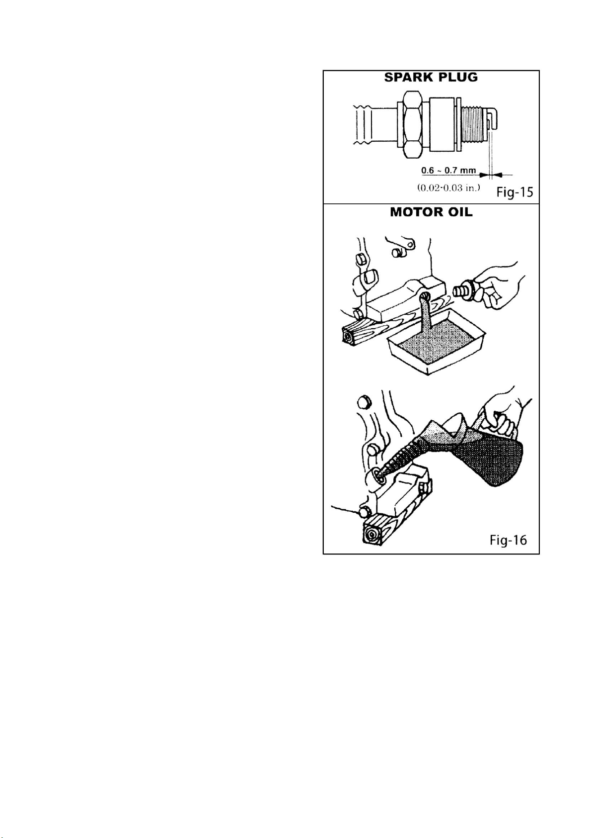
Honda and Kama motors are fitted with an oil alert device which
will stop the motor or prevent starting when the crankcase oil
level falls below a safe level.
Drive belt
Tension of the drive belt is adjustable.Loosen the four nuts on
the bolts which secure the motor to the base plate,Adjust the set
screws which bear against the motor crankcase to achieve the
requiredbelttension.Ensurethat thefour nuts andthe setscrew
locknutsaretightenedafteradjustment.
ACCESSORIES
Transport Trolley-facilitates handling.Hooks into the base-
plate.Fitted with 200mm rubber tyres.
FOR SAFETY OPERATION
!This safetyalert symbol identifies
importantsafetymessagesthroughout
thismanualand onthemachine.
Whenyouseethis symbol,carefullyread
the messagethat follows.Yoursafetyis
atstake!
Foreword:
It is important to readthis manual carefullyso
that you will fully understand the operational
characteristics and performanceofthe plate
compactor.Propermaintenance proceduresWill
insure long lifeand top performance of the unit.
Safety:
Thissectionoutlines basicsafetyprocedures that
applytotheoperation,maintenanceand
adjustmentoftheplatecompactor.This
unitisdesignedasapowerful,productive
machine thatshouldbe operated withrespectand
caution.
Misuse orcarelessnesscanresult inserious injury
orpropertydamage,orboth.Safetyprecautions
mustbeobservedatalltimes.
Operator Qualifications:
Before operating this equipment,anindividual
shouldreadthis manual.Wheneverpossible,he
should be shownhow to operate the unit byan
experiencedoperator.Inexperience ishazardous
in operatinganymachineorattachment.Trialand
error is not the wayto become familiar with a
pieceofequipment.This isexpensive,cuts
equipmentlife andcan createmachinedowntime.
Inexperiencecancauseinjuryordeath.The
machine should not be left unattended when
operating.
GeneralSafety:
! CAUTION
Protectionrequired.Wearhardhat.shatterproof
glasses,steeltoedbootsandotherprotective
devices requiredbyjobconditions.Avoidjewelry
orlooseclothing.These manycatchoncontrols
or in moving partsand cause seriousinjury.
Starting Safety:
! CAUTION
Poisonousfumes.Start and operate only in well
ventilatedarea.Breathingexhaustgases can
resultin sicknessordeath.
Servicing Safety:
! CAUTION
Flammableliquid.Stopengineanddonot
smokeorallow workinimmediatearea
when refueling.Fireor explosioncould
resultfromflamesorsparks.
Movingparts.Shutdownenginebefore
performing.Service or maintenance.
Contact with moving parts can cause
serious injury.
High temperature.Allowmachineand
engineto coolbeforeperformingservice
or maintenance.Contact with hot
componentscancauseserious bums.
Engine
See engine operationsmanual
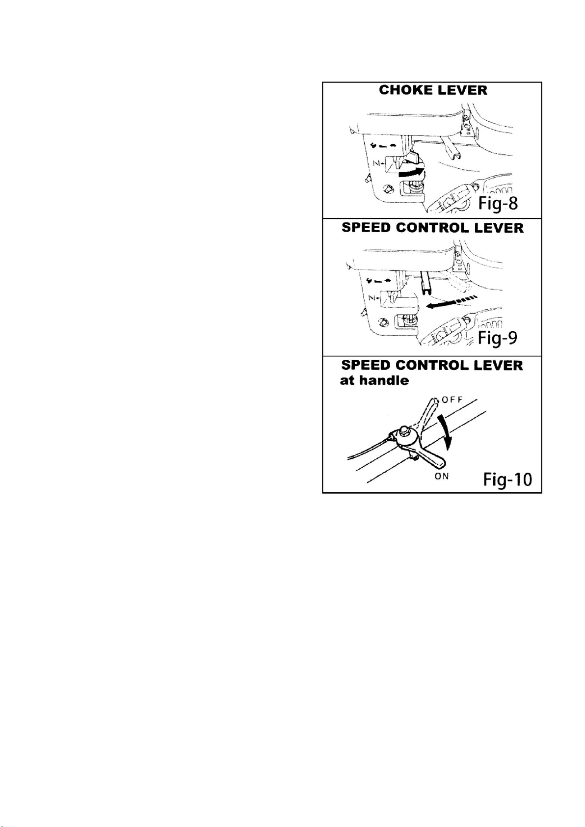
SHUTDOWN
EMERGENCYSHUTDOWN
Movethrottleleverto "OFF"position
andalso turn stop switchto "OFF".
NORMALSHUTDOWN
Movethrottleleverquicklyfrom
"ON"to "OFF" and runengine for3
to5 minutesatlowspeed.After
engine cools, turn stop switch to
"OFF"position.Closefuelshutoff
valve.

4
HAZARDS AND RISKS
NEVER allow any person to operate the machine without
adequate instruction.
ENSURE all operators read ,understand and follow the
operating instructions.
SERIOUS INJURYcould result from improper orcareless use of
thismachine
Plate compactors are heavy units and should be positioned by
two people of appropriate strength.Using the lifting handles
provided on the machine, along withcorrect lifting techniques.
! MECHANICALHAZARDS
DO NOToperatethemachine unlessallprotectiveguardsare
in place.
KEEPhands and feet clear of rotating and moving parts as they
willcauseinjuryif contacted.
ENSURE that the motor operation switch is in the OFF position
and the spark plug ignition lead isdisconnected before removing
the guardsormakingadjustments.
ENSURE both the machine and the operator are stable by
setting up on level terrain and the machine will not tip over, slide
or fall while in operation or unattended.
DO NOTleavethemachine inoperation whileit isunattended
ENSURE that the walls of a trench are stable and will not col-
lapse due to the action ofthe vibration,priortocommencing
compaction.
ENSURE that the area to be compacted does not contain any
"live" electrical cables,gas,water or communication services
which may be damaged bythe action ofthe vibration.
EXERCISECAREwhen operatingunit.Exposuretovibrationor
repetitive work actions may be harmful to handsand arms.
NEVER stand on the unit while it is operating.
DO NOT increase the governed no-load motor speed above
3,500 r/min. Any increase may result in personal injury and
damageto themachine.
BE CAREFUL not to come in contact with the muffler when the
engineis hot,sinceit cancausesevereburns.
ENSURE that repairs to the motor and machine are carried out
personnel.
! FIRE & EXPLOSION HAZARDS
PETROL is extremely flammable and explosive under certain
conditions.
ENSURE that petrol is only stored in an approved storage
container.
DO NOTrefuel the motor whileit is in operation or hot.
DO NOTrefuel the motor in the vicinityof sparks, a naked flame
or a person smoking.
DO NOT over fill the fuel tank and avoid spilling petrol when
refueling.Spilled petrol or petrol vapour may ignite.If spillage
occurs,ensure that the area is drybeforestartingthe motor.
ENSURE thatthe fuel tank capis securely fitted after refueling.
! CHEMICALHAZARDS
DO NOT operate or refuel a petrol or diesel motor in a confined
area withoutadequate ventilation.
CARBON MONOXIDE exhaust gases from internal combustion
motordrivenunitscancausedeathinconfined spaces.
! NOISE HAZARDS
EXCESSIVENOISEcan lead totemporaryor permanent loss of
hearing.
WEAR an approved hearing protection device to limit noise
exposure.As required by Occupational Health and Safety
regulations.
PROTECTIVE CLOTHING
ALWAYS wear approved hearing protection when working in a
confined work space.Protective goggles and a dust mask
should be worn when workingin adustyenvironment.
Protective clothing and footwear may also be desirable when
working withhot mixbitumen.
!ADDITIONALHAZARDS
Slip/Trip/Fallisamajorcauseofserious injuryordeath.
Bewareofuneven orslipperyworksurfaces.
Exercise care when working in the vicinity of unprotected holes
orexcavations
OPERATION
GENERAL OPERATION
The machine is best suited to the compaction of bituminous and
granular materials e.g. granular soils, gravels and sands or
mixtures of both.Cohesive soils such as silt and clay are best
compacted using the impact force produced by a vibrating
rammer.
Where possible the site should be graded and leveled before
commencingcompaction.
Correct moisture content in soil is vital to proper compaction.
Water acts as a lubricant to help slide soilparticles together. Too
littlemoisturemeansinadequatecompaction;too muchmoisture
leaves water-filled voids that weaken the soil's load bearing
ability.
Use unleaded grade petrol and ensure that the fuel is free from
contamination.
The vibratory motion provides a self propelling action.Position
the handle at the opposite end of the machine to the vibrator.

5
Start the motor using the recoil starter.(If the motor is fitted with
an on/offswitch this mustfirst be turned to ONbefore starting.)
For more information on starting and correct operating
procedures of the motor,refer to the motor operation manual
sup-plied with the unit.
Increase the motor speed to the maximum setting using the
handthrottle lever,before commencingcompacting.
The machine should be controlled by grasping the handle with
both hands and applying restraint to control the forward
motion.Forward or backward motion has problem,adjust the red
handle or nuts(item 21,22in components list)
Steer the machine by moving the handle sideways to the right or
left.
ALWAYS maintain good footing so that you do not slip and loose
control whenstartingor operating the machine
1.Prior tooperation
1-1.Make sure thatalI dirt,mud,etc.,are thoroughly
removed fromthe unitprior tooperation.Special
effortshouldbe given tothe bottomfaceofthe
vibratingplate and those areasadjacent to the
cooling air inlet of engine,carburetor,and air
cleaner.
1-2.Check alI bolts and screws for tightnessand make
sureall bolts and screws are securely tightened.
Loosebolts andscrewsmaycausedamagetothe
Unit.
1-3.Check the V-belt for tightness.ThenormaIslack
shouldbe approximately10-15mm(1/2")whenthe
beltsare forcibly depressedin the middleposition
between thetwo sheaves.
If there is excess belt play,there couldbe a
decrease intheimpactforceorerraticvibration,
causing machinedamage.
1-4.Checktheengineoilllevelandiftheengineoil
Ievelislow,it should berefilled.Use the proper
motor oil as suggested in the tablebelow.(Fig-1)
1-5.Remove the oil plugin the vibratorassembly and
checkthe oillevel.Makesurethecompactoris
level when checking.Theoillevelshouldbeup to
the oilplug.Everymonthorevery200hoursof
operation,replacetheoil.
! lMPORTANT:
Use themotoroil SAE
Whenchanging theoil,theoldoil
canbedrainedbytippingtheunit.
The oil will draineasily while it is
hot.
Season Temperature
Gradof Motoroil
(higher than MSclass)
Spring Summeror Autumn
+120°Ft0 +40°F
SAE30
Winter+40°F to +15°F
SAE20
Below+15°F
SAEl0W-30
1-6.Aregulargradegasolineshouldbeusedinthe
engine.
Whenfillingthefueltank,make sure the fuel
filter is used.
2.Caution
2-1.Becareful with the operatingplace and ventilation.
Avoidoperating the machine in a closed room,
tunnel,orother badlyventilatedplaces.since its
exhaust contains deadlypoisonouscarbon
monoxide.Ifthemachine isemployed
unavoidable operated in sucha place,discharge
the exhaust out sidethe roomby asuitable means.
2-2.Becareful with the hot members.
Mufflers andother hotmembers are dangerous.
Do nottouch them with unprepared hand.
2-3.Observe withthe followingcautions when
transporting.ClampfueItankcap securely.and
turn the fuel valveOFF at the sourceduring
Drain gasoline from fueltank before transporting
overa long distance or on rough roads.

6
2-4.Stop engine withoutfail before replenishing fuel tank.
Never replenish gasoline whilethe engine is
runningorremainshot otherwisespilled or
evaporated fuel is liable to catch firefrom engine
sparksormufflerheat.
Wipeoffspilled fuel,ifany,before starting engine.
Be careful not to Spill fuel.
2-5.Keep jnflammables away from the vicinity of
the exhaustport.
Be careful with gasoline match,straw and other
inflammables,sincethe exhaustport issubjected
to a high temperature.
3.Starting
GasolineEngine
3-1.Turn the STOPSWITCH clock-wise to theposition
"I"(ON).Fig-3
3-2.Openthe fuelcock.Fig-4
3-3.Set the speed control lever1/3 to 1/2 of the way
towards thehigh speed position.Fig-5
3-4.Close the choke lever.
If theengineis warm or the ambient temperature
is high,open thechokeleverhalf-way.orkeepit
fullyopen.
If theengineis cold or the ambient temperature is low,
closethe choke leverfully.Fig-6
3-5.Pull the starterhandleslowly until
resistanceisfelt.Thisis the
"compression"point.Returnthehandle
to its original position and pull
swiftly.
Do notpull out the ropealI the way.
Afterstartingthe engine,allowthe
starterhandleto return toitsoriginal
position while still holding the handle.
Diesel Engine
3-6.Tum the throttle leverto STARTposition(open by
about30degrees) Fig-5-D
3-7.Operate Starter
In caseof recoil starter.
Bypullingthe starterknob slowly,you will reach
suchpoint where resistance become
strong(compression point).bypullingitfurther,
you will Finda point where resistance is reduced.
Return the knobbut slowly return it original
Fig-7-D

7
! CAUTION
Do not pull the rope all the way and do not
take your hand off the pulled knob but slowly
return it original position.
3-8.After startingup the engine,besuretoperforma
warmuptheengine,besure to perform a warm
up run for2 to 3 minutes.Thisshouldbe
performed without fail,particularly during
winterseason.
4. Operation
4-1.As theengine warms up,gradually move the choke
lever to the OPEN position Fig-8
4-2.Move the speed controllever from the LOW tothe
HIGHposition.Whentheenginespeedreaches
approximately2,300-2,600 PRM,the centrifugal
clutchengages.Ifthe enginespeedincreased very
slowly,it ispossiblethattheclutch canslip.Do
notoperatethespeedcontrol leverslowly.
Fig-9,10
OILALERT SYSTEM
The OilAlert System is designed to prevent engine
damage caused by an insufficientamountof oil in the
crankcase.Beforetheoillevelin thecrankcasecanfall
below a safe limitthe OilAlert System will
automaticallystop the engine(theengineswitch will
remain in the ON position).
! NOTICE
If the engine stops and will not restart, check
the engine oil level.
4-3.Whencompactingasphalt,it isadvisabletopaint
the bottom face Of the vibrating plate with diesel
fuel.
This will assist in preventing theplate from
stickingtotheashalt.
4-4.Whenshuttingoffthevibrator,turn thespeed
control lever from the HIGH to LOW position.Do
notmove thespeedcontrolleverslowly.
5.Transportation
5-1.Be sure to stop the engine while transporting.
5-2.Screw up the fuel tank capsecurely and closethe
fuel valve to avoidfuel leaking.
5-3.1ntransportationbycar,fixmachinesecurelynotto
move nor to fall down.
In case Of drivingfor longdistanceor at off-road,
tank out fuel from tank.

8
6.Shutdown
To stoptheengineinan emergency,turn thestop
switch to the OFFposition.
Undernormalconditions,usethefollowingprocedure:
6-1.Set the speedcontrolleverat the lowspeed
positionand allowthe engineto run at low speed
for 2 or 3 minutes before stopping.
6-2.Tumthestopswitchto theOFF position.Fig-12
6-3.Close the fuelcock.Fig-13
7.Service&storage
! CAUTION
Flammableliquid:Stopengineanddonot
smokeor allowwork inimmediate area when
refueling.Fire or explosioncould result from
flamesor sparks.
Movingparts:Shutdown enginebefore
performingserviceormaintenance.Contact with
movingparts cancauseseriousinjury.
High temperature:Allow machine and engine to
Cool before performing service 0r maintenance.
Contact with hot components can cause serious
burn.
7-1.Dail Service
A. Remove mud,dirt,etc., fromthe unit.
B. Clean bottom face of the vibrating plate.
C. Check the air cleaner element and clean if
necessary
D.Checkall nuts,bolts, and screws fortightness
andre-tighten asnecessary.
7-2.WeeklyService
A.AIRCLEANERSERVICE Fig-14
Dirty air cleaner element will causestarting
difficulty.powerloss,enginemalfunctions,and
shortenenginelifeextremely.
Keep the air cleanerelement clean.
URETHANEFOAM ELEMENT
Removethe elementand washit inkerosene or
dieselfuel.Then saturate it in a mixture of3 parts
kerosene or diesel fuel andI part engine oil.
Squeeze the element to remove the mixture and
installitintheaircleaner.
URETHANEFOAMDUALSTRUCTURE
1.Clean the urethane foam in the same wayas
describedabove.
2.Wash theelementin keroseneordieselfuel.
Saturate it in a mixture of 3parts kerosene or
dieselfueland l partengine oil.Shakeoff
excessiveoil and re-install.

9
B.Remove spark plug,clean and adjust the spark plug gap to
0.6-0.7mm(0.02-0.03 in.). Fig-15
C.drain the motor oil of the engine and replace with new
specifiedoil.Fig-16
! NOTE:When the engine is new,the first oil change must be
made after 20 hours of operation and replenish the oil tank
before operating.
7-3. MonthlyService
Change the oil in the vibratorassembly.
7-4. Storage
Whenstoringthecompactorforlongperiodsafter
operation.
A. Thoroughly drain the fuel fromthe fuel tank fuel
pipeandcarburetor.
B. Poura few drops of motor Oil into the cylinderby
removing thespark plug.
Rotate the engineseveral times byhand SO that the
cylinderinterioris covered withoil.
C. Cleanthe outer surfaceof the machine with an oil
moistenedcloth.Cover the unit andstore in a
humidity-free.dust-freearea.
CARE AND PREVENTIVE MAINTENANCE
Check the oil levelin the motorcrankcase daily.
Check the vibrator oil level weekly.
Inspect the rubber anti vibration mounts for wear or
deterioration.
Cleanthe underside of theplateregularlyto preventabuildup of
material.
SERVICE
Change the oil in the motor crankcase regularly to minimise
Wear.
Inspect, clean and/or replace the motor air cleaner regularly,
particularly when operating in a dusty environment.
Inspect,cleanand/orreplace thespark plug regularly
Check all fasteners for tightness as the machine is subject to
vibration.
Check v belt tension,wear and that it is running true, adjust or
replaceasrequired.

10
! CAUTION
Inspection and other services should always be carried out on
hardand levelground with the engine shutdown.
Inspection and Maintenance Service Tables.
1.To make sure your plate compactor is always in good
working condition before using,carry out the maintenance
inspection in accordance with Tables 1through 3.
TABLE1. MACHINE INSPECTION
ITEM
NOURS OF
OPERATION
REMARKS
Looseor Missing
Screws
Every8hours
(everyday)
Damaged Parts
Every8hours
(everyday)
Functionof Controlling
System Part
Every8hours
(everyday)
Vibrator OilCheck
Every100hours
Vibrator Oil
Replacement
Every300hours
replenish600ml
V-belt(clutch) Check
Every200hours
BatteryCheck
Every100hours
! CAUTION
These inspection intervals are for operation under normal
conditions.Adjustyourinspectionintervals based onthenumber
hours plate compactor is in use,and particular working
conditions.Vibratorcase uses 320# gear oilas lubricant.
! CAUTION
Fuelpipingand connections shouldbe replaced every2 years.
TABLE2. ENGINE CHECK
ITEM
HOURS OF OPERATION
Oil or Fuel Leak
Every 8 hours(everyday)
Tightness of Fastening
Threads
Every 8hours(every day)
EngineOil Check and
Replenishment
Every 8 hours(everyday)
(Replenishto specified maximum level)
EngineOil Replacement
After first 25 hoursthenevery 50to
100 hours
AirFilterCleaning
Every 100hours
Seeseparateengine manualfordetailsonenginecheck
.
DailyService
●Check forleakage of fuel or oil.
●Checkforloosescrewsincludingtightness.SeeTable 3
below(tighteningtorque),forre-tightening:
TABLE3.
TIGHTENING TORQUE(in.kg/cm) Diameter
Material
6mm
8mm
10mm
12mm
14mm
16mm
18mm
20mm
4T
70
150
300
500
750
1,100
1,400
2,000
6-8T
100
250
500
800
1,300
2,000
2,700
3,800
11T
150
400
800
1,200
2,000
2,900
4,200
5,600
*
100
300~
350
650~
700
*(Incasecounter-partisofaluminum)
(Threads inusewiththismachineareallrighthanded
)
Materialandqualityofmaterialismarkedoneachbolt
,
andscrew
.
●Remove soil andclean the bottom of compaction plate.
●Checkengineoil.

11
SPECIFICATIONS
BEARINGS
The following bearings ate sealed:
Centrifugal clutch-grease lubricated
Vibrator-oil bath lubricated
FINISH
The machine is finished in gold equipment enamel, the handle in black baked enamel. Exposed metal surfaces are zinc
electroplated for corrosion protection.
TROUBLESHOOTING
SYMPTOM POSSIBLE CAUSES AND CORRECTION
Motor will not start.
-Check the ON/OFF switch to ensure that it is switched ‘ON’.
-Check the fuel supply.
-If a Honda or Kama motor is fitted check the crankcase oil level as an oil
sensor device is fitted to these motors which prevents starting and stops
the motor when the oil level is low.
-Ensure the spark plug ignition lead is connected
-Chock the carburettor let and bowl to ensure they are clean.
Motor stops.
-Check:the fuel supply.
-Check that the fuel cock is turned on.
-Check the condition of the air filter.
Petrol Motor lacks power.
-Check the condition of the air filter.
-Check the condition of the spark plug.
Insufficient vibration
-Check for a slipping or a missing v belt.
-Check that the motor governed speed is 3,500r/min.
Machine is not moving freely
-Check the under side of the plate for a build up of material
Model
61012
Engine
Air-cooled, 4-cycle, single cylinder
Engine type
Petrol, Loncin 200F
Power kw(hp)
4.7(6.5)
Weight kg(lbs)
180(287)
Frequency vpm
4600
Centrifugal Force kn
22
Compaction Depth cm(in)
50(19)
Travel Speed cm/s(in/s)
20(8)
Efficiency m2/hr (ft2/hr)
450(4844)
Plate Size cm(in)
66X38(26x15)
Dimension cm(in)
82X44.5X100(32X17.5X40)

12
REPLACEMENT PARTS LIST
Major components and vibrator assembly parts list as followings.

13
·Major components list
ITEM N0.
PART N0.
DESCRIPTl0N
QUANTITY
1
300001
Hexagonal bolt M8x25
1
2
300002
Washer,lock M8
1
3
300003
Washer,plat M8
1
4
300004
Clutch assembly
1
5
300005
V-belt
1
6
300006
Engine
1
7
300007
Nut M10
4
8
300008
Washer,lock M10
4
9
300009
Washer,plat M10
4
10
300010
Guard hook
1
11
300011
Throttle lever
1
12
300012
Grip
1
13
300013
Handle
1
14
300014
Shock absorber
2
15
300015
Hexagonal bolt M8x25
4
16
300016
Rubber coupling
2
17
300017
Rubber
2
18
300018
Washer,plat 12.5x40x2.5
2
19
300019
Hexagonal bolt M12x65
2
20
300020
Vibrator control
1
21
300021
Nut M14x1.5x7
4
22
300022
Washer,plat M14
2
23
300023
Vibrating plate
1
24
300024
Vibrator assembly .
1
25
300025
Hexagonal bolt Ml0x45
4
26
300026
Washer,plat M10
4
27
300027
Base
1
28
300028
Belt cover(upper)
1
29
300029
Washer,plat M8
2
30
300030
Washer,lock M8
2
31
300031
Hexagonal bolt M8 x 20
2

14
·Major components list

15
ITEM NO.
PART NO.
DESCRIPTION
QUANTITY
1
300001
Belt cover(blow)
1
2
300002
Screw M8x25
1
3
300003
Washer,lock M8
1
4
300004
Washer,plat 8.5x32x2.5
1
5
300005
Pulley,driven
1
6
300006
Bearing cover/pulley
1
7
300007
Packing
4
8
300008
oil seal 28x50x10
1
9
300009
Case cover
1
10
300010
Stop dowel 8x35
2
11
300011
Packing
1
12
300012
Bearing 42206
4
13
300013
Stop ring 42
5
14
300014
Socket head bolt M6x20
13
15
300015
Washer,lock M6
13
16
300016
Bearing cover/shut-off
2
17
300017
Hexagonal bolt M8x60
1
18
300018
Spring washer M8
20
19
300019
Nut M8
1
20
300020
Stopper
1
21
300021
Stop dowel M20x31-21
1
22
300022
Eccentric rotator,drive
1
23
300023
Key 8x7x25
1
24
300024
Ecc.rotary shaft,drive
1
25
300025
Key 12x8x50
1
26
300026
Key 12x8x20
1
27
300027
Gear,drive
1
28
300028
Eccentric rotator,driven
1
29
300029
Ecc.rotary shaft,driven
1
30
300030
Dial plate(R/L)
2
31
300031
Gear,driven
1
32
300032
Cylinder
1
33
300033
Packing
1
34
300034
Cover,cylinder
1
35
300035
Washer,lock M5
3
36
300036
Socket head bolt M5xl0
3
37
300037
Vibrating case
1
38
300038
Knock pin
1
39
300039
Position rod
1
40
300040
Groove
1
41
300041
Washer,copper 5x32x2.5
1
42
300042
Washer,lock M5
1
43
300043
Socket head bolt M5x10
1
44
300044
Rotator
1
45
300045
Lever
1
46
300046
O-ring
3
47
300047
Holder
1
48
300048
Washer,lock M10
2
49
300049
Socket head bolt M10x30
2

16
50
300050
Spring
1
51
300051
Bearing 16008
2
52
300052
Plug,oi1 M12x1.25x10
2
Table of contents
Other Stark Power Tools manuals

Stark
Stark red line HG 2002D User manual

Stark
Stark 53500 Original instruction manual

Stark
Stark 61006 User manual

Stark
Stark 53501 Original instruction manual

Stark
Stark red line JS 750 User manual

Stark
Stark 56030 Original instruction manual

Stark
Stark 61006 Original instruction manual

Stark
Stark 61014 Original instruction manual

Stark
Stark RH 1800DB User manual