Starret MMD Series User manual

The Better Solution
Twin Column Testing Frames
User Guide for
MMD Series Material Testers
FMD Series Force Testers

starrett.com 3
Table of Contents
Page
General Safety Precautions 4
Warnings 4
1.0 INTRODUCTION 6
1.1 System Description 6
1.2 System Safety and Labeling 7
1.3 Product Support 8
1.4 Calibration and Verification 8
1.5 Software Options 8
1.5.1 Using L3 Material Test Software 9
1.5.2 Using L2 Plus Advanced Force Analysis Software 9
1.5.3 Using L2 Force Measurement Software 9
2.0 SYSTEM DESCRIPTION 10
2.1 MMD Series Product Specifications 10
2.2 FMD Series Product Specifications 11
2.3 Common Specifications 14
2.3.1 Power Requirements 14
2.3.2 Fuse Ratings 14
2.3.3 Noise Level Rating 14
2.3.4 Environmental Specifications 15
2.3.5 Cyclic Testing 15
2.3.6 Load Hold Testing 15
2.3.7 Test Frame Weights 15
2.4 MMD/FMD Dimension Drawings 16
3.0 LIFTING AND HANDLING 19
3.1 General Precautions 19
3.2 Unpacking Your System 20
3.3 Moving Your System 22
3.3 Positioning Your System for Use 23
4.0 INSTALLATION 24
4.1 Customer Responsibilities 24
4.2 Starrett Responsibilities 24
4.3 Site Considerations 25
4.4 Setting Input Voltage 26
4.4.1 Verifying Your Input Power Source 27
4.4.2 Setting Input Voltages 28
4.5 Connecting System Components 29
4.5.1 Installing L3/L2 Plus Workstations 29
4.5.2 Installing the L2 Tablet 30
4.5.3 Installing Base Clevis Assembly 31
4.5.4 Installing Load Cell Sensor 31
4.5.5 Installing Load Cell Sensor Clevis Assembly 34
4.5.6 Installing Test Fixture 34
4.5.7 Installing Extensometers (MMD Series only) 35
4.5.8 Installing a Printer 35
4.5.9 Installing Bench Mounting Clips 36
4.5.10 Using the Optional Splinter Shield 37
Page
5.0 SYSTEM OPERATION 38
5.1 Operating Principles 38
5.2 Operator Controls 38
5.2.1 Emergency Stop Switch 38
5.2.2 Mains Power Switch 39
5.2.3 Crosshead Jog Switch 39
5.2.4 Test Start/Stop Switch 40
5.2.5 Over Travel Limit Switches 41
6.0 USING YOUR MMD SERIES TEST FRAME 42
6.1 System Settings Options 42
6.1.1 Setting Crosshead Travel Limits 42
6.1.2 Setting Crosshead Maximum Travel Velocity 43
6.1.3 Setting Grip Protection 44
6.1.4 Setting Load Cell Limit 45
6.1.5 Using Deflection Compensation Correction 46
6.2 Using L3 Series Material Test Software 47
6.2.1 Starting an L3 Test 47
6.2.2 Pausing an L3 Test 47
6.2.3 Stopping an L3 Test 48
7.0 USING YOUR FMD SERIES TEST FRAME 49
7.1 Using L2 Plus Series Force Analysis Software 49
7.1.1 Starting an L2 Plus Test 49
7.1.2 Stopping an L2 Plus Test 49
7.2 Using L2 Series Force Measurement Software 50
7.2.1 Starting an L2 Test 50
7.2.2 Stopping an L2 Test 50
8.0 SYSTEM MAINTENANCE 51
8.1 Preventive Maintenance 51
8.1.1 Daily Maintenance Checks 51
8.1.2 Authorized Field Maintenance 51
8.1.3 Cleaning 51
8.1.4 Lubrication 51
8.2 Maintenance Procedures 51
8.2.1 Travel Limits 51
8.2.2 Emergency Stop 52
8.2.3 Fuse Replacement 52
9.0 CALIBRATION AND VERIFICATION 52

4
Product Warranty
Starrett force measurement products carry a one-year (from date of
purchase) warranty against defects in material and
workmanship (parts and labor), subject to factory inspection.
The L.S. Starrett Company will repair or replace, at its option, any part
or parts found to be defective in workmanship or material. Starrett
warrants repaired or replaced parts for the balance of the original
warranty period or 90 days, whichever is longer. Parts returned to the
factory under warranty will be repaired at no charge. Freight charges to
the factory will be paid by the customer. Return freight charges to the
customer will be paid by Starrett.
This warranty does not cover damages from such causes as abuse,
accident, neglect, fire or freight damage. It does not apply to defects
resulting from modifications made by the customer or improper use of
the system or its components.
Disclaimer of Liabilities
The L.S. Starrett Company shall have no liability or responsibility to the
customer or any other person or entity with respect to any liability, loss
or damage caused or alleged to be caused directly or indirectly by this
documentation, or the hardware described in it. This includes but is not
limited to any interruption of service, loss of business or anticipatory
profits, or consequential damages resulting from the use or operation
of hardware or equipment.
starrett.com 5
General Safety Precautions
Force measurement systems are potentially hazardous. Prior to
operating your testing system, Starrett recommends that you read and
understand the instruction manuals for your system and components
and that you receive training on the proper use of this equipment from
your authorized Starrett representative.
Observe all warnings and cautions identified in this manual for your
equipment. A warning identifies a function that may lead to injury
or death. A caution identifies a hazard that may lead to damage to
equipment or loss of data.
Starrett products, to the best of our knowledge, comply with various
national and international safety standards as they apply to material
and force measurement testing. This Starrett product has been tested
and found to comply with the following recognized standards:
• EN61010-1 Safety Requirements for Electrical Equipment
• EN61000-6-3 EMC Generic Emissions Standard
• EN61000-6-1 EMC Generic Immunity Standard
Starrett also certifies that this product complies with all relevant EU
directives and carries the CE mark.
Electromagnetic Compatibility
Your MMD Series material test system is designed to comply with
International Electromagnetic Compliance (IEC) standards.
To ensure reproduction of this EMC performance, connect this
equipment to a low impedance ground connection. Typical suitable
connections are a ground spike or the steel frame of a building.
Warnings
Emergency Stop
Press the emergency stop button whenever you feel there is an unsafe
condition during a test. The emergency stop button removes power to
the motor drive system causing the crosshead to stop.
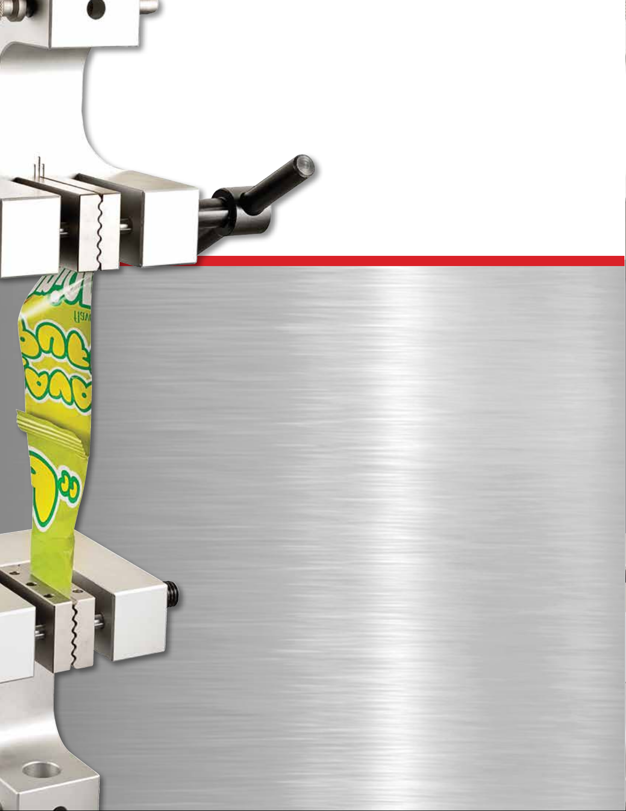
Flying Debris
Eye protection, protective clothing and splinter/safety shields should
be used whenever any possibility exists of a hazard from the failure of
a sample, assembly or structure under test. Due to the wide range of
materials that may be tested and that may result in a failure which may
cause bodily injury, the precautions and preventative methods taken
prior to testing is entirely the responsibility of the owner and the user
of the equipment.
Crush Hazard
Always use caution when installing or removing apparatus and your
sample material between the frame’s crosshead and the base. A
potential pinch/crush hazard exists. Keep clear of the testing fixture,
and particularly the jaw faces at all times. Keep clear of the crosshead
during movement. If available, always make sure the Pinch Load
feature is enabled. This will stop inadvertent crosshead operation if in
manual mode. Always ensure that other personnel cannot operate the
system while you are working within the test fixture area.
Electrical Hazard
Disconnect equipment from the electrical power supply before
removing any electrical safety covers. Disconnect power when
replacing fuses. Never reconnect power while the covers are removed.
Never operate the system with protective covers removed.
Rotating Machinery Hazard
Always disconnect power before removing covers that protect the user
from the internal rotating mechanisms. If maintenance to the drive
mechanism is required, and power is needed to perform maintenance
to the drive system, maintenance should be performed by an
authorized Starrett representative who has received factory training on
performing such procedures.
Warning Labels
Listed below are the warning labels used in this manual including their
definitions. Please pay particular attention to these labels and sections
within this manual denoted with a warning label.
HAZARD: This label identifies a potentially dangerous hazard
that may lead to serious injury to personnel.
WARNING: This label alerts the user of a potentially serious
hazard that may result in injury to personnel and damage to
equipment.
CAUTION: This labels advises the user to proceed using
caution while performing this action. Failure to do so may
harm equipment.
NOTE: This label is used to call-out important information
including helpful operating instructions.
6
1.0 Introduction
Thank you and congratulations for selecting the Starrett FMD or MMD
Series twin column testing frame.
Your MMD and FMD Series testing frame may be used for tension and
compression testing including specific test methods such as peak,
break, constant hold, flexural, shear, peel, coefficient of friction and
more.
Your MMD and FMD testing frame should be used with Starrett
equipment and accessories only.
For optimum performance, your MMD and FMD testing frame should
be maintained and serviced annually by an authorized Starrett
representative.
HAZARD
MMD and FMD test frames are used in applications with
inherent hazards from high forces, rapid motions and stored
energy.
Users should be aware at all times of moving components
that are potentially hazardous, particularly moving
crossheads.
Failure to read and follow all operating instructions can result
in serious injury to personnel and damage to equipment and
facilities.
Operation and service of MMD and FMD test frames should
be by authorized personnel trained in their safe operation.
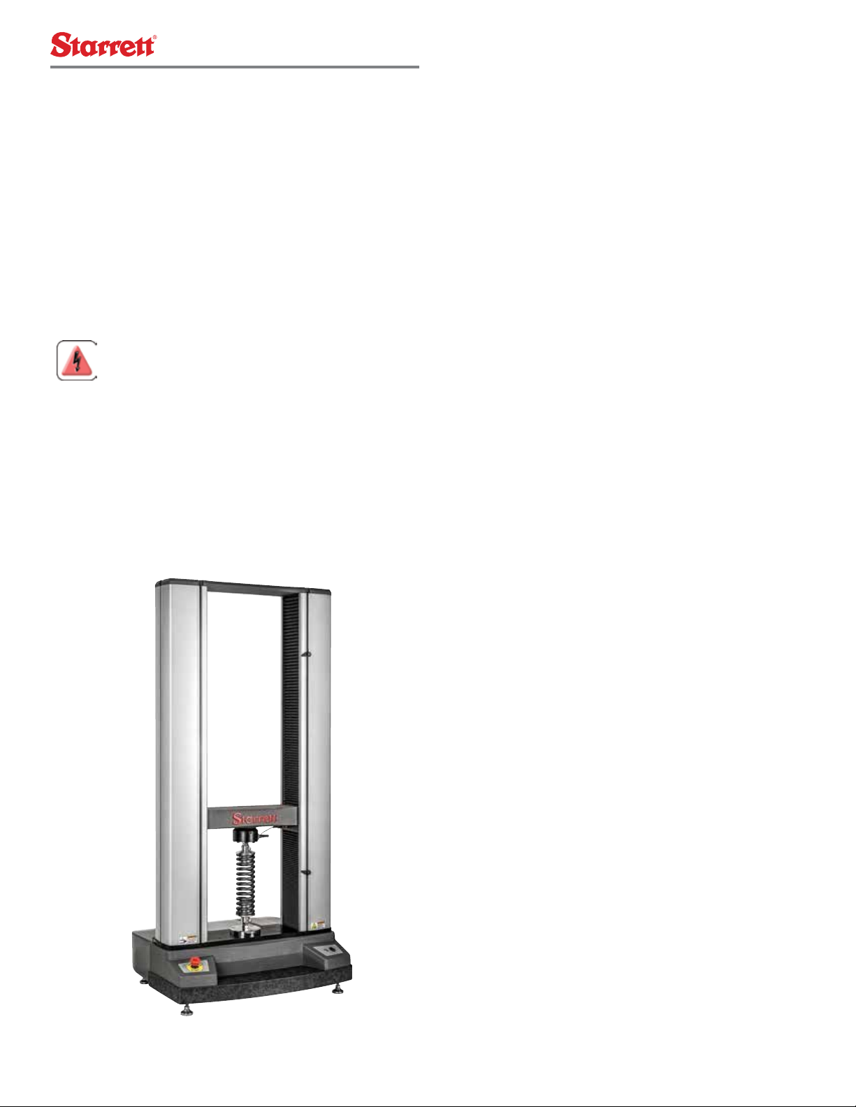
Starrett Twin Column Test Frames
1.1 System Description
Your Starrett MMD and FMD Series test frames are twin column testing
frame that make up any of the following testing systems:
• L3 Series System used for material testing
• L2 Plus Series System used for advanced force measurement and
analysis
• L2 Series System use for force measurement
L3 Series System
An L3 Series System uses our L3 Series software operating on an
all-in-one touchscreen workstation (L3 Workstation), combined with
an MMD Series testing frame. L3 Series Systems are used to measure
stress, strain, load, distance, height and time. L3 Series Systems are
optimized for research & development, engineering and advanced
quality control applications involving material characterization.
L2 Plus Series System
The L2 Plus Series System uses our L2 Plus Series software operating
on an all-in-one touchscreen workstation (L2 Plus Workstation),
combined with an FMD Series testing frame. The L2 Plus Series
Systems are used to measure load, distance, height and time. They
cannot be used with extensometers and cannot be used to measure
and analyze stress or strain. L2 Plus Series Systems are used for
advanced force measurement and analysis.
L2 and S2 Series System
L2 Series Systems are designed for high-volume testing in a production
environment. The L2 Series System uses our L2 Series software
operating on a table personal computer, combined with an FMD Series
testing frame. L2 Series Systems are used to measure load, distance,
height and time. The cannot be used with extensometers and cannot
be used to measure stress or strain. L2 Series Systems are optimized
for the production floor- they are easy-to-use, and provide basic force
measurement results.
The S2 Series System is an application-specific system used
exclusively for testing compression and extension springs.
MMD Series Test Frames
MMD Series test frames are designed for more complex material
testing and therefore, these testing frames have higher performance
specifications compared to the FMD Series. MMD Series further
distinguish themselves from an FMD Series by having two (2)
extensometer inputs, plus optional analog inputs, analog outputs and
digital I/O that may be used with ancillary equipment.
FMD Series Test Frames
FMD Series are for high load capacity force testing. FMD Series have
lower performance specifications compared to the MMD Series. FMD
Series cannot be used with extensometers. FMD Series cannot use
analog input or analog outputs. FMD Series can be supplied with
optional digital I/O.

starrett.com 7
1.2 System Safety and Labeling
ISO and ANSI safety labels are affixed to Starrett equipment to alert
users and operators of the equipment to warnings and cautions.
System users should obey all warnings and cautions and should be
trained on the safe operation of this equipment by an authorized
Starrett representative.
Starrett Twin Column Safety Labels
Front view Rear view
Pinch Hazards
Crush Hazards
Mechanical
Hazards
Electrical
Hazards
HAZARD
Never operate the MMD or FMD test frame without the
protective cover over the mechanical and electronic
components.
HAZARD
Servicing the MMD or FMD test frame should be performed
by authorized Starrett personnel only.
8
1.3 Product Support
If you ever require product support for your Starrett system,
contact your authorized Starrett representative. Authorized Starrett
representatives are listed on our website at www.starrett.com. In the
event that your Starrett representative may not be able to assist you,
contact Starrett at one of our many international sales offices. Our
sales offices are listed on our website at www.starrett.com.
1.4 Calibration and Verification
Your Starrett MMD and FMD Series test frames are calibrated and
tested at our factory prior to shipment to you. Our factory calibrations
are traceable to national standards. Prior to shipment, Starrett
performs the following at our manufacturing facility:
• Force Calibration per ASTM E4
• Displacement Calibration per ASTM E2309/E2309M
• Speed Verification ASTM E2658
If you require an on-site calibration, Starrett or a Starrett authorized
representative can perform a calibration at your location to comply with
these international calibration standards.
NOTE
MMD Series used for material testing require calibration at
the time of installation.
Starrett recommends that you calibrate your system at least annually.
More frequently calibrations may be required depending on the
frequency of which the system is used. If your system is calibrated to
ASTM E4, ASTM E2309/E2309M or equivalent international standards,
the system must be calibrated whenever the system is relocated, e.g.
moved from its location where the previous calibration occurred.
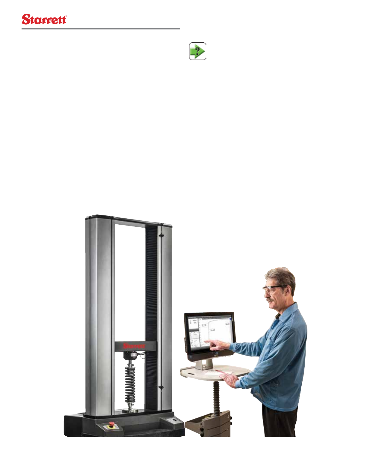
1.5 Software Options
Your Starrett MMD and FMD Series test frame is designed to be used
for material testing and force measurement applications. Starrett
offers three different software products, each one optimized for its
intended application. The user interface differs depending on the
software selected. Force measurement applications utilize a tablet
computer operating our L2 Series software or an all-in-one desktop
touchscreen computer with our L2 Plus Series advanced force
measurement and analysis software. Material testing applications
utilize an all-in-one desktop touchscreen computer with our L3
Series material test software. Contact your Starrett representative for
assistance in selecting the correct software application for your needs.
FMD Series with L2 Plus Workstation
starrett.com 9
1.5.1 Using L3 Material Test Software
Starrett L3 Series material test software is designed for general
purpose material testing application and for use on a variety of
materials including metals, composites, rubber, plastic, elastomers,
films, foils, adhesives, etc. The software is optimized for use for
material characterization, material research & development and
material quality and specification verification. L3 Series software
supports a variety of testing methods for load, distance, stress, and
strain based on industry standards from ASTM, DIN, ISO, TAPPI and
others.
1.5.2 Using L2 Plus Force Measurement Software
Starrett L2 Plus Series force measurement software is designed for
detailed force analysis in the laboratory. The software is optimized
for research & design, engineering and quality control testing where
load and distance are measured and where detailed analysis, including
force characterization is necessary.
1.5.3 Using L2 Force Measurement Software
Starrett L2 Series force measurement software is designed for high
volume production environments. The software is optimized for
in-situ production or quality control testing where load and distance
are measured on a variety of products including adhesives, medical
devices, foam/film, springs, etc.
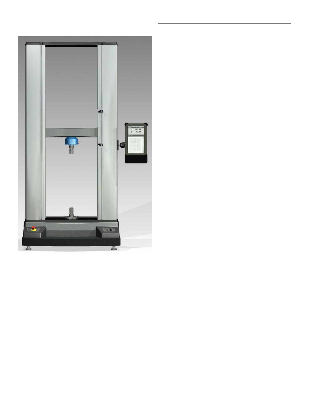
FMD Series with L2 Tablet Controller
10
2.0 System Descriptions
2.1 MMD Series Test Frames
The Starrett MMD Series are twin column, electromechanical test
frames designed for material testing applications. The MMD Series
are bench top systems ideal for tensile, compression, shear, flexural,
cyclic and other forms of testing applications.
Three model test frames are available:
• MMD-10K Series
• MMD-30K Series
• MMD-50K Series
The MMD Series has been designed to be used with Starrett L3
software for material testing operating on an all-in-one, touchscreen
computer.
The MMD Series features include:
• Precision motion controls including powerful motors with excellent
acceleration and position resolution
• High Axial Stiffness with granite base and adjustable deflection
compensation and linear error correction
• Pre-loaded ball screws and bearings and low-stretch belts for
outstanding responsiveness and repeatability
• Extra heavy-duty crosshead for testing loads up to 50kN
• Data sampling from 1 to 2000Hz
• USB communications
• Interfaces for up to two (2) extensometers capable of exceeding
strain measurement accuracies per ASTM E83, ISO 9513 and EN
10002-4.
• Load measurement using IEEE 1451.4 TEDs-compliant load cell
sensors with accuracies up to 0.5% of reading down to 1/1000 of
load cell capacity.
• Digital and analog I/O channels for interfacing with ancillary
testing equipment or for incorporating programmable logic control
• Easy to use fixture mounting for the many hundreds of different
test fixtures and grips that may be used
• Worldwide sales and service support
Test Frame
Your MMD Series test frame consists of a granite base, cast-aluminum
base plate, two (2) extruded aluminum columns and a cast-aluminum
top plate. The precision aluminum crosshead is engineered for
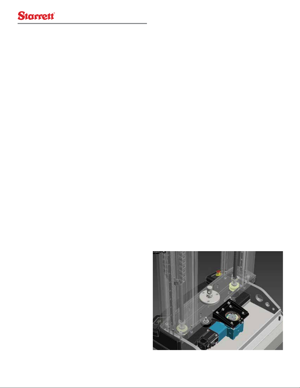
MMD /FMD Series System Drive System
minimal deflection under full loads at full velocity. Within each
column are precision ballscrews. The ballscrews are preloaded. The
ballscrews rotated synchronously driven by a precision motion control
system. Overall, the system components provide an industry-leading
system with extraordinary axial stiffness.
Drive System
The drive system for your MMD Series test frame resides within the
back housing protected by a lightweight fiberglass housing. The drive
system connects to the lower end of the ballscrews using a belt and
pulley system. Motor rotation rotates the ballscrews synchronously
which moves the crosshead up or down with excellent position control
resolution.
Load String
The load string consists of the load cell sensor, clevis adapter and test
fixture. The load cell is mounted to the crosshead using a set screw
that secures the load cell to the crosshead surface.
Starrett recommends using low-profile load cell sensors for material
testing because of their excellent axial stiffness.
Starrett recommends that your load cell sensor is attached to a base
adapter. The base adapter is standard with ULC Series load cells and
optional for MLC Series load cells. The base adapter helps ensure a
proper surface mounting.
The test fixture is mounted using the clevis adapter. The clevis
adapter has an M16 thread and comes in either a 15.9mm or 31.8mm
diameter. The clevis adapter threads into the load cell sensors. The
test fixture slides onto the clevis adapter and is secured using locking
rings and a grip pin.
Communications
Communications between the L3 Series workstation and your MMD
Series test frame is via USB 2.0.
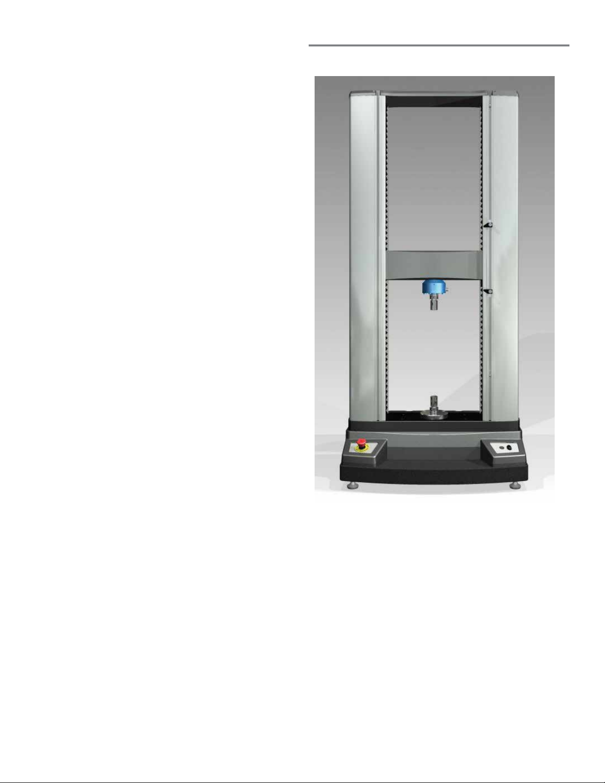
starrett.com 11
MMD/FMD Series System Design
2.2 FMD Series Test Frames
The Starrett FMD Series are twin column, electromechanical test
frames designed for force testing applications. The FMD Series are
bench top systems ideal for tensile, compression, shear, flexural, cyclic
and other forms of testing applications.
Three model test frames are available:
• FMD-10K Series
• FMD-30K Series
• FMD-50K Series
The FMD Series has been designed to be used with Starrett L2 Plus
software for advanced force measurement testing operating on an all-
in-one, touchscreen computer. Or, the FMS Series may be used with
Starrett L2 software for basic force measurement testing operating on
a tablet personal computer.
The FMD Series features include:
• Precision motion controls including powerful motors with excellent
acceleration and position resolution
• High Axial Stiffness with granite base and adjustable deflection
compensation and linear error correction
• Pre-loaded ball screws and bearings and low-stretch belts for
outstanding responsiveness and repeatability
• Extra heavy-duty crosshead for testing loads up to 50kN
• Data sampling from 1 to 2000Hz
• USB communications
• Load measurement using IEEE 1451.4 TEDs-compliant load cell
sensors with accuracies up to 0.5% of reading down to 1/1000 of
load cell capacity.
• Digital I/O channels for interfacing with ancillary testing equipment
or for incorporating programmable logic control
• Easy to use fixture mounting for the many hundreds of different
test fixtures and grips that may be used
• Worldwide sales and service support

12
MMD Series Product Specifications
Specification MMD-10K Series MMD-30K Series MMD-50K Series
Load Capacity
kN
kgf
lbf
10
1000
2250
30
3000
6750
50
5000
11,250
Crosshead Speed - MINIMUM mm/min
in/min
0.001
0.00004
0.001
0.00004
0.001
0.00004
Crosshead Speed - MAXIMUM mm/min
in/min
1500
60
1500
60
750
30
Position Control Resolution µm
µin
0.05
1.9
0.025
0.9
0.025
0.9
Frame Axial Stiffness kN/mm
lbf/in
72
412,844
150
855,513
161
918,367
Vertical Test Space1mm
in
1270
50
1245
49
1220
48
Total Crosshead Travel mm
in
1162
45.75
1137
44.75
1111
43.75
Column Spacing mm
in
424
16.7
424
16.7
424
16.7
Total Height mm
in
1626
64
1626
64
1626
64
Total Width mm
in
787
31
787
31
787
31
Total Depth mm
in
736
29
736
29
736
29
Test Frame Weight kg
lb
136
300
192
425
225
500
Load Measurement Accuracy ±0.5% of reading down to 1/1000 of load cell capacity. Starrett load cell sensors are supplied with a Certificate of Calibration
traceable to NIST. Starrett recommends verification of load cell accuracy during installation per ASTM E4, ISO 7500-1 or EN 10002.
Position Measurement Accuracy2
±0.0002 inch (±5 µm)
Strain Measurement Accuracy ±0.5% of reading down to 1/50 of full scale with ASTM E83 class B or ISO 9513 class 0.5 extensometer
Crosshead Velocity Accuracy ±0.1% of set speed at zero or constant load hold
Data Sampling 1 to 2000Hz
Digital I/O
12 total channels
Channel 1 & 2 for Power (5-24V)
Channels 3 thru 10 for either digital inputs or outputs
Channels 11 & 12 for Ground
Analog Inputs 1 channel @ ±10V
Analog Outputs 2 channels @ 0-10V
Extensometer Ports 2 channels for independent connection to an extensometer(s)
USB Interface 1 USB 2.0 connector
Single Phase Voltage (Vac) ±10% 100-120Vac 220-240Vac 220-240Vac 220-240Vac
Maximum Power (A) Amps 4.0 1.5 3.7 3.7
Frequency 50/60Hz
Operating Temperature °C
°F
+10 to +38 °C
+50 to +100 °F
Storage Temperature °C
°F
-40 to +66 °C
-40 to +150 °F
Humidity 10% to 90%, non-condensing
CE Compliance MMD Series Systems meet all relevant CE standards
Notes:
1 Total vertical space is the distance from the top surface of the base plate to the bottom surface of the crosshead, excluding load cell sensor,
test fixtures, and clevis adapter.
2 Assumes Linear Error Correction and Deflection Compensation have been performed on test frame.

starrett.com 13
FMD Series Product Specifications
Specification FMD-10K Series FMD-30K Series FMD-50K Series
Load Capacity
kN
kgf
lbf
10
1000
2250
30
3000
6750
50
5000
11,250
Crosshead Speed - MINIMUM mm/min
in/min
0.001
0.00004
0.001
0.00004
0.001
0.00004
Crosshead Speed - MAXIMUM mm/min
in/min
1500
60
1500
60
750
30
Position Control Resolution µm
µin
0.05
1.9
0.025
0.9
0.025
0.9
Frame Axial Stiffness kN/mm
lbf/in
72
412,844
150
855,513
161
918,367
Vertical Test Space1mm
in
1270
50
1245
49
1220
48
Total Crosshead Travel mm
in
1162
45.75
1137
44.75
1111
43.75
Column Spacing mm
in
424
16.7
424
16.7
424
16.7
Total Height mm
in
1626
64
1626
64
1626
64
Total Width mm
in
787
31
787
31
787
31
Total Depth mm
in
736
29
736
29
736
29
Test Frame Weight kg
lb
136
300
192
425
225
500
Load Measurement Accuracy ±0.5% of reading down to 1/1000 of load cell capacity. Starrett load cell sensors are supplied with a Certificate of Calibration
traceable to NIST. Starrett recommends verification of load cell accuracy during installation per ASTM E4, ISO 7500-1 or EN 10002.
Position Measurement Accuracy2
±0.001inch (±20 µm)
Crosshead Velocity Accuracy ±0.1% of set speed at zero or constant load hold
Data Sampling 1 to 2000Hz
Digital I/O
12 total channels
Channel 1 & 2 for Power (5-24V)
Channels 3 thru 10 for either digital inputs or outputs
Channels 11 & 12 for Ground
USB Interface 1 USB 2.0 connector
Single Phase Voltage (Vac) ±10% 100-120Vac 220-240Vac 220-240Vac 220-240Vac
Maximum Power (A) Amps 4.0 1.5 3.7 3.7
Frequency 50/60Hz
Operating Temperature °C
°F
+10 to +38 °C
+50 to +100 °F
Storage Temperature °C
°F
-40 to +66 °C
-40 to +150 °F
Humidity 10% to 90%, non-condensing
CE Compliance MMD Series Systems meet all relevant CE standards
Notes:
1 Total vertical space is the distance from the top surface of the base plate to the bottom surface of the crosshead, excluding load cell sensor,
test fixtures, and clevis adapter.
2 Assumes Linear Error Correction and Deflection Compensation have been performed on test frame.
14
2.3.3 Noise Level Rating
The noise output for your MMD and FMD Series does not exceed
70dBa. Noise levels do not include noise from specimen breaks.
WARNING
Noise caused by sample fracture may exceed 70 dBa,
therefore, personal ear protection is recommended for these
types of applications.
2.3.4 Environmental Specifications
Your MMD and FMD Series is designed for use under normal labora-
tory conditions. Protective measures may be required if excessive dust,
corrosive fumes, electromagnetic fields or hazardous conditions are
encountered.
MMD Series Specification
Operating Temperature +10°C to +38°C (+50°F to +100°F)
Storage Temperature -40°C to +66°C (-40°F to +150°F)
Humidity 10% to 90% non-condensing
Environmental Conditions
Designed for use under normal laboratory conditions.
Protective measures maybe required if excessive dust,
corrosive fumes, electromagnetic fields or Hazardous
conditions are encountered.
Environment Specifications
2.3 Common Specifications
2.3.1 Power Requirements
The power specifications for Starrett MMD and FMD Series testing
frames are shown below.
Models
Electrical Phase
Single Phase (Vac) ±10%
Maximum
Power (A)
Frequency
(Hz)
MMD-10K
FMD-10K 100-120Vac 4.0 50/60
MMD-10K
FMD-10K 220-240Vac 1.5 50/60
MMD-30K
FMD-30K 220-240Vac 3.7 50/60
MMD-50K
FMD-50K 220-240Vac 3.7 50/60
Power Specifications
CAUTION
Your MMD Series requires “clean” and stable electrical
power. Power fluctuations and surges may cause perfor-
mance problems that may lead to extensive damage to your
test frame.
NOTE
An in-line power surge protector is recommended for all
installations.
2.3.2 Fuse Ratings
See Fuse Table (below).
HAZARD
Make sure to shut all power to your MMD or FMD Series test
frame to OFF. Dangerous voltage may cause personal injury.
NOTE
The MMD-10K and FMD-10K Series used with 100V or 120V
input power use two (2) 6.3A slow-blow fuses.
NOTE
All MMD and FMD Series used with 220-240V input power
use two (2) 3.5A slow blow fuse.
WARNING
Always replace the fuse with the correct type and amp rating.
Model Input Power Frequency Fuse Type Fuse Size Number Required
Littlefuse Brand
Part Number
FMD-10K
MMD-10K 100-120Vac 4.0A 50-60Hz 6.3A Slow-Blo 5 x 20mm 2 each 021806.3MXP
FMD-10K
MMD-10K 220-240Vac 1.5A 50-60Hz 3.15A Slow-Blo 5 x 20mm 2 each 02183.15MXP
FMD-30K
MMD-30K
FMD-50K
MMD-50K
220-240Vac 3.7A 50-60Hz 6.3A Slow-Blo 5 x 20mm 2 each 021806.3MXP
Fuse Specifications

starrett.com 15
2.3.5 Cyclic Testing
Cyclic testing is defined as tests where the frame constantly reverses
direction. Cyclic testing on MMD and FMD test frames is limited to a
continuous 24 hour duration @ 1Hz sampling.
CAUTION
The MMD and FMD test frames are not suitable for fatigue
testing applications.
2.3.6 Load Hold Testing
Constant load testing is defined as tests where the frame maintains a
constant load for a specified period of time, e.g. creep and relaxation
applications. Cyclic testing on MMD and FMD test frames is limited to a
continuous 24 hour duration at 1Hz sampling rate.
2.3.7 Frame Weights
MMD and FMD Series weights are listed below, including dimensions.
Model
Machine
Weight
Shipping
Weight1
Height
mm/in
Width
mm/in
Depth
mm/in
MMD-10K
FMD-10K
136 kg
300 lbs
~320 kg
~700 lbs
1626mm
64 in
787mm
31 in
736mm
29 in
MMD-30K
FMD-30K
192 kg
425 lbs
~340 kg
~750 lbs
1626mm
64 in
787mm
31 in
736mm
29 in
MMD-50K
FMD-50K
225 kg
500 lbs
~360 kg
~800 lbs
1626mm
64 in
787mm
31 in
736mm
29 in
Physical Weights and Dimensions
1The shipping weight will vary depending on the accessories included
with your order. Accessories are packaged in a single shipping crate.
NOTE
All shipping containers used for the 10K, 30K and 50K frames
are 38.5” W x 36” D x 74” H (97.8 x 91.4 x 188.0 cm).
16
TITLE:
MATERIAL:
Assembly, Twin Column, 10KN, Overall Dimensions
FINISH:
REV:DRAWING NUMBER:
10510-02 00
DATE: SCALE:
1 : 15
7/30/2013
The information in this drawing is the CONFIDENTIAL property of MetLogix. Disclosure or duplication
without prior approval is strictly prohibited.
0.00 [0.0]: ±0.030 [±0.75]
0.000 [0.00]: ±0.004 [±0.10]
0.0000 [0.000]: ±0.0010 [±0.025]
UNITS = INCH [MM]
TOLERANCES: (UNLESS NOTED)
DESIGN BY: DRAWN BY:
Craig Smigel cjs
SHEET:
OF
1 2
REVISION HISTORY
REV. DESCRIPTION DATE BY
00 As Issued 07/30/13 cjs
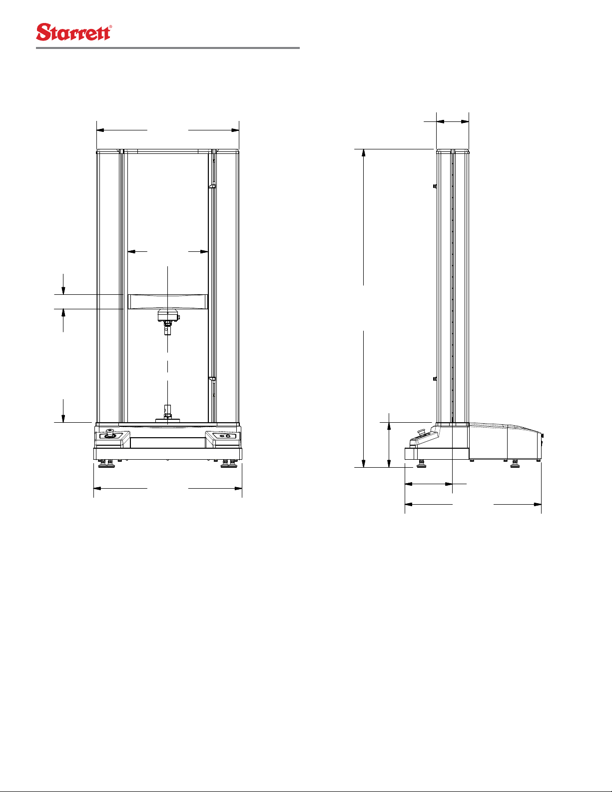
29.7 [754]
16.7 [424]
3.0 [76]
50.00
4.25
1270.0
108.0
[]
MAX-MIN HEIGHT
31.0 [787]
28.5 [724]
10.0 [254]
9.4 [238]
66.4 [1685]
6.7 [170]
2.4 MMD and FMD Dimension Drawings
10kN Load Capacity Series Test Frames

starrett.com 17
30kN Load Capacity Series Test Frames
TITLE:
MATERIAL:
Assembly, Twin Column, 30KN, Overall Dimensions
FINISH:
REV:DRAWING NUMBER:
10530-02 00
DATE: SCALE:
1 : 15
7/30/2013
The information in this drawing is the CONFIDENTIAL property of MetLogix. Disclosure or duplication
without prior approval is strictly prohibited.
0.00 [0.0]: ±0.030 [±0.75]
0.000 [0.00]: ±0.004 [±0.10]
0.0000 [0.000]: ±0.0010 [±0.025]
UNITS = INCH [MM]
TOLERANCES: (UNLESS NOTED)
DESIGN BY: DRAWN BY:
Craig Smigel cjs
SHEET:
OF
1 2
REVISION HISTORY
REV. DESCRIPTION DATE BY
00 As Issued 07/30/13 cjs
29.7 [754]
16.7 [424]
4.0 [102]
49.00
4.25
1244.6
108.0
[]
MAX-MIN HEIGHT
31.0 [787]
28.5 [724]
10.0 [254]
10.4 [263]
67.4 [1711]
6.7 [170]
MMD and FMD Dimension Drawings

18
TITLE:
MATERIAL:
Assembly, Twin Column, 50KN, Overall Dimensions
FINISH:
REV:DRAWING NUMBER:
10550-02 01
DATE: SCALE:
1 : 13
7/30/2013
The information in this drawing is the CONFIDENTIAL property of MetLogix. Disclosure or duplication
without prior approval is strictly prohibited.
0.00 [0.0]: ±0.030 [±0.75]
0.000 [0.00]: ±0.004 [±0.10]
0.0000 [0.000]: ±0.0010 [±0.025]
UNITS = INCH [MM]
TOLERANCES: (UNLESS NOTED)
DESIGN BY: DRAWN BY:
Craig Smigel cjs
SHEET:
OF
1 2
REVISION HISTORY
REV. DESCRIPTION DATE BY
01 As Issued 07/30/13 cjs
16.7 [424]
48.00
4.25
1219.2
108.0
[]
MAX-MIN HEIGHT
31.0 [787]
28.5 [724]
67.4 [1711]
10.4 [263]
5.0 [127]
10.0 [254]
6.7 [170]29.7 [754]
50kN Load Capacity Series Test Frames
MMD and FMD Dimension Drawings

starrett.com 19
3.0 Lifting and Handling
The MMD and FMD Series twin column testing frames are heavy. Any
lifting and positioning should be done by authorized personnel in
accordance to local safety standards, e.g. training required by Occupa-
tional Safety and Health Act (OSHA) in the United States, or comparable
safety standards when installed internationally.
Proper rigging equipment is required for lifting and positioning all MMD
and FMD Series test frames. Personnel responsible for test frame
lifting and position must follow the instructions within this manual.
Personnel should contact Starrett if they have any questions about how
to safely lift and position the MMD or FMD Series test frames.
Starrett recommends leaving the MMD and FMD Series test frame
in its packaging while moving the instrument to its final site location
within your facility.
CAUTION
Make sure hallways and door openings are large enough to
safely move your MMD and FMD Series to its final site loca-
tion.
Make sure that floors leading to the final site location are
rated to support the weight of the MMD and FMD Series
while in its Starrett Packaging.
3.1 General Precautions
Starrett recommends that only individuals experienced with the
operation of lifting equipment and rigging techniques should attempt to
lift or move your MMD and FMD Series testing frames.
Equipment operators must have the appropriate licenses and have
complied with your local safety standards (e.g. the appropriate training
required by OSHA in the U.S. or appropriate safety institutions around
the world).
WARNING
NEVER lift the frame by the top plate. This plate does not
support the weight of the frame. The plate could break and
cause personal injury and equipment damage.
WARNING
Do not use a lifting device or straps rated for less than twice
the weight of the load frame. All lifting devices and straps
must be rated for a capacity at least twice the weight of the
load frame.
WARNING
Do not tilt an unsupported load frame more than 15-degrees
when it is in the upright position.
Lift by Crosshead
Do NOT lift by top plate
20
3.2 Unpacking Your System
Starrett recommends that you wait to unpack your MMD or FMD Series
once it has been located in its final site location.
Your MMD and FMD Series should be moved using a forklift or crane to
its final site location.
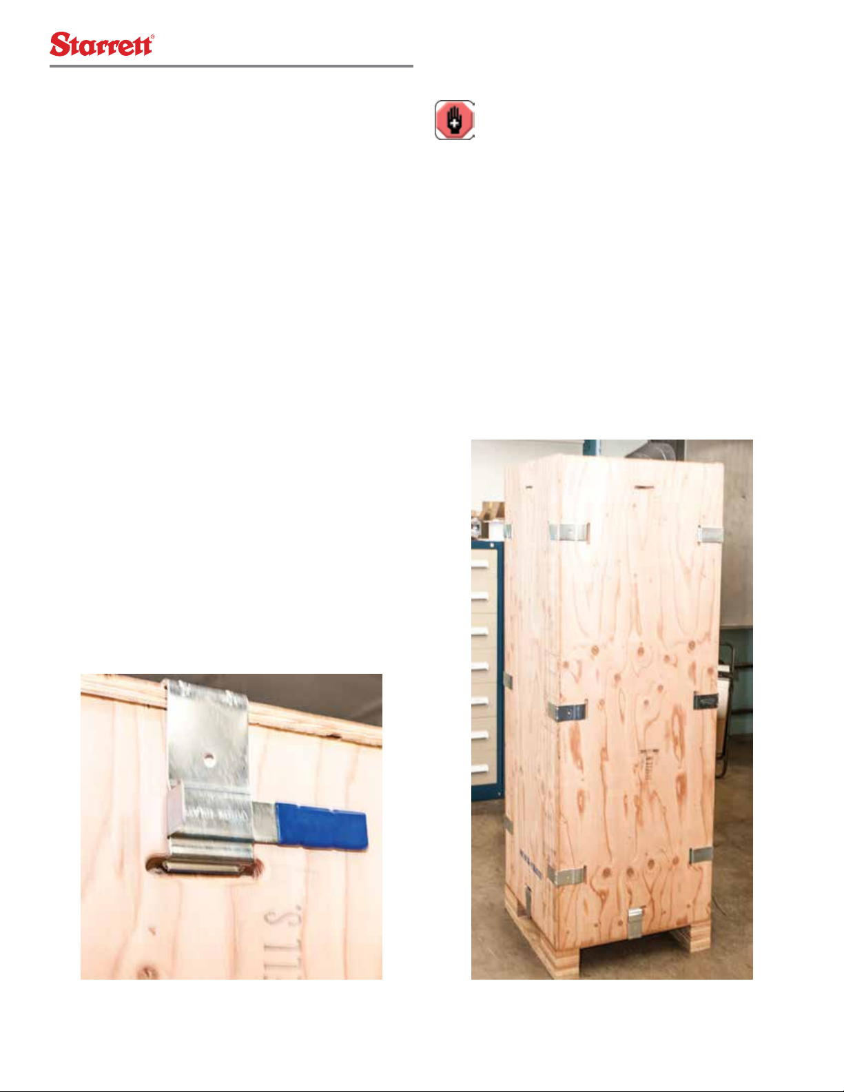
Starrett uses environmentally safe portable crating systems to trans-
port the MMD or FMD Series. These systems are reusable, so take
care to store them flat when you are finished removing your test frame.
Disassemble your packaging create as follows:
1. Remove the metal clips holding the top plate of the crate system.
2. Remove the wooden top plate.
3. Remove the metal side clips.
4. Remove one of the metal base clips.
5. Remove the wooden side where you removed the metal base clip.
6. Repeat steps 3-5 as your work around each side of the crate
system.
7. Remove the shrink wrap vapor barrier around the test frame. DO
NOT USE A KNIFE. Take care not to cut the shrink wrap as you
may accidentally damage the surface finish.
8. Review the Packing List to ensure all components have been
shipped. Contact Starrett if you find any accessories or compo-
nents missing.
9. Remove all accessories and components from the base and save
to a side location. Do NOT disassemble or remove any compo-
nents or parts from the Accessory packages. Retain all packaging
materials until the system is satisfactorily installed and all parts,
components and accessories are
accounted for and located.
10. Prepare to move the MMD or FMD test frame to its final site
location.
Starrett Crate Tool
WARNING
When removing the wooden sides from the crate system, you
should work with the help of an assistant to keep the oppos-
ing sides from falling off the bottom skid.
Once the top and sides of the crate system have been removed, leave
the MMD or FMD test frame in the base on the skid. The skid is
required if you choose to life the frame under the base.
Starrett Crate System
This manual suits for next models
1
Table of contents
Popular Test Equipment manuals by other brands


Zehntner
Zehntner ZOL 1150 instruction manual

MULTI MEASURING INSTRUMENTS CO.,LTD.
MULTI MEASURING INSTRUMENTS CO.,LTD. MCL-800IRV instruction manual

PeakTech
PeakTech P 3441 manual

Viavi
Viavi MTS 2000 Quick Card

Pintek
Pintek DP-16V instruction manual

Armada Technologies
Armada Technologies Pro48 instruction manual


