manuals.online logo
Brands
  1. Home
  2. •
  3. Brands
  4. •
  5. AEMC instruments
  6. •
  7. Test Equipment
  8. •
  9. AEMC instruments 3640 User manual

AEMC instruments 3640 User manual

AEMC®Instruments • (800) 945-2362 • www aemc.com 99-MAN 100438v3
• Locate grounding points on the tankers and transfer pump.
• Make connections to damaged tanker first to avoid a potential spark.
• When possible, grounding systems should be established up hill and outside of the
Hot Zone.
• Resistance measurement should be compliant with your local jurisdiction which
usually follows NFPA 472 @1000or lessor NEC @ 25or less, lower is always
better. Higher resistance means longer static discharge time.
STEP 1:
Hazmat Grounding & Bonding
Site Considerations
Installing the Grounding System
NOTE: One or more rods may be needed for each grounding system to obtain an
acceptable grounding resistance. Multiple rods should be 3to 6feet apart and
connected to each other via jumper cable.
• Install/establish three separate static grounding systems, one for the distressed
tanker (X1), one for the recovery tanker (X2) and one for the pump (X3). When the
pump is not mounted to the fire truck, they should be at least 10 feet apart.
• The grounding sites should be up hill and up wind as well as outside of the
distressed tanker’s hot zone.
WARNING:
Make sure the ground rod is fully screwed tight into the Driver
/
Extractor tool before driving it into the ground to avoid thread damage.
AEMC®Instruments • (800) 945-2362 • www aemc.com 99-MAN 100438v3
STEP 2:
Conduct independent Fall-of-Potential tests on each of the
grounding systems.
1. Insert the auxiliary test electrode Za few inches into the ground and 50
to 80 feet away at a location that is central to the three grounding system
Xrods.
2. Insert the auxiliary test electrode Ya few inches into the ground at a
distance approximately 30 to 45 ft from the first ground system X1 and in
a straight line with the Zelectrode.
3. Connect the Red, Blue and Green test wires to the grounding rod(s),
electrodes and instrument as shown.
4. Press and hold the Test button until reading stabilizes to measure the
resistance.
5. Repeat steps 2, 3 and 4 for grounding systems X2 and X3.
After achieving the acceptable resistance, disconnect the meter and auxiliary rods Y
and Zbefore Step 3, connecting the tankers and pump to their grounding systems.
Testing the Grounding System
Ω
Press To
Measure
X-Z
Xv-Y
Xv-Y
ZYX
C1 P2 C2
Fault
Hi Resistance
Hi Noise
GROUND RESISTANCE TESTER
MODEL 3640
AUTORANGING
REFER TO USER MANUAL
FOR FAULT WARNING LIGHT
EXPLANATIONS
!
®
INSTRUMENTS
Y
50 to 80 ft
Z
X
30 to 45 ft
NOTE: Readings should be below 1000Ω, 750Ω, 100Ωor 25Ωas defined by local
authority.
AEMC®Instruments • (800) 945-2362 • www aemc.com 99-MAN 100438v3
STEP 3:
Following the diagram, perform the below steps in the following order:
Connect a grounding cable to the distressed tanker first and then to
its grounding system X1.
Connect a grounding cable to the recovery tanker first and then to its
ground system X2.
Connect a grounding cable to the transfer pump first and then to its
grounding system X3.
Connect a bonding cable to the distressed tanker first and then to
the recovery tanker.
Connect the hoses to the pump and tankers.
Begin the transfer process.
NOTE: X3 is not needed if the pump is mounted to a fire truck.
Connect to the Grounding System
1 2
3 4
5 6
7 8
9
Accessories (Sold Separately):
Static Ground Test System
HAZMAT Kit
Cat. #2155.01
PRODUCT PACKAGING
Ships with:
150 ft Red Wire on Reel
Cat. #5000.04
Waterproof Utility Case with inserts
Cat. #2155.13
Ground Rod Driver /Extractor Tool
Cat. #2155.11
Handles supplied with
Red and Blue Reels
30 ft Lead (green)
Cat. #5000.01
Also Includes:
• User Manual
• 8 AA Batteries -Uninstalled
• Flathead Screwdriver
Lead, Set of 2, color-coated
5 ft (Red and Blue) for Reels
Cat. #5000.34
5 Spaded lugs
Cat. #5000.10
(2 Sets of) 3 Copper Clad Ground Rods with
2 Ground Rod Couplers
Cat. #2155.10 (3 Rods & 2 Couplers)
150 ft Blue Wire on Reel
Cat. #5000.07
150 ft Jumper Cable
Cat. #2155.16
50 ft Bonding Cable
with REB Clamp
Cat. #2155.12
(3) 50 ft Ground Cable with
REB Clamp on one end and Mueller
Clip on the other.
Cat. #2155.14 (1 Reel)
Ground Tester Model 3640
Cat. #2114.92
Extra Handle for Reels
Cat. #5000.64
(2 Sets of) 3 10ft Ground Rod
Jumper Cables
Cat. #2155.15 (1 Set of 3)
Ground Tester
Calibration Checker
Cat. #2130.59
USB Drive containing
Training Video
Set of two, 14.5" T-shaped
Auxiliary Ground Electrodes
Cat. #2135.39
OV_HazmatKit.indd Rev 0618
AEMC®Instruments • (800) 945-2362 • www aemc.com 99-MAN 100438v3
Accessories (Sold Separately):
Static Ground Test System
HAZMAT Kit
Cat. #2155.01
PRODUCT PACKAGING
Ships with:
150 ft Red Wire on Reel
Cat. #5000.04
Waterproof Utility Case with inserts
Cat. #2155.13
Ground Rod Driver /Extractor Tool
Cat. #2155.11
Handles supplied with
Red and Blue Reels
30 ft Lead (green)
Cat. #5000.01
Also Includes:
• User Manual
• 8 AA Batteries -Uninstalled
• Flathead Screwdriver
Lead, Set of 2, color-coated
5 ft (Red and Blue) for Reels
Cat. #5000.34
5 Spaded lugs
Cat. #5000.10
(2 Sets of) 3 Copper Clad Ground Rods with
2 Ground Rod Couplers
Cat. #2155.10 (3 Rods & 2 Couplers)
150 ft Blue Wire on Reel
Cat. #5000.07
150 ft Jumper Cable
Cat. #2155.16
50 ft Bonding Cable
with REB Clamp
Cat. #2155.12
(3) 50 ft Ground Cable with
REB Clamp on one end and Mueller
Clip on the other.
Cat. #2155.14 (1 Reel)
Ground Tester Model 3640
Cat. #2114.92
Extra Handle for Reels
Cat. #5000.64
(2 Sets of) 3 10ft Ground Rod
Jumper Cables
Cat. #2155.15 (1 Set of 3)
Ground Tester
Calibration Checker
Cat. #2130.59
USB Drive containing
Training Video
Set of two, 14.5" T-shaped
Auxiliary Ground Electrodes
Cat. #2135.39
OV_HazmatKit.indd Rev 0618

Other AEMC instruments Test Equipment manuals

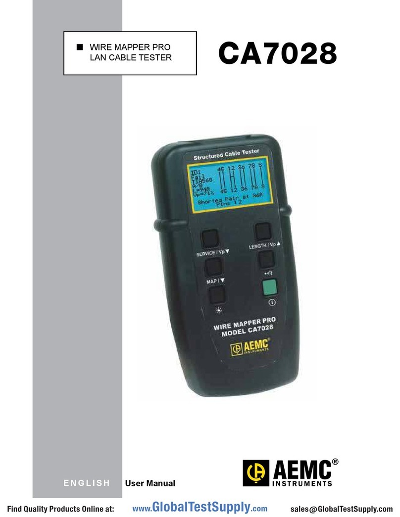
AEMC instruments CA7028 User manual

AEMC instruments

AEMC instruments CA7028 User manual

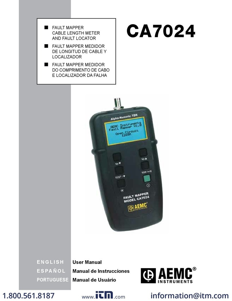
AEMC instruments CA7024 User manual

AEMC instruments

AEMC instruments CA7024 User manual

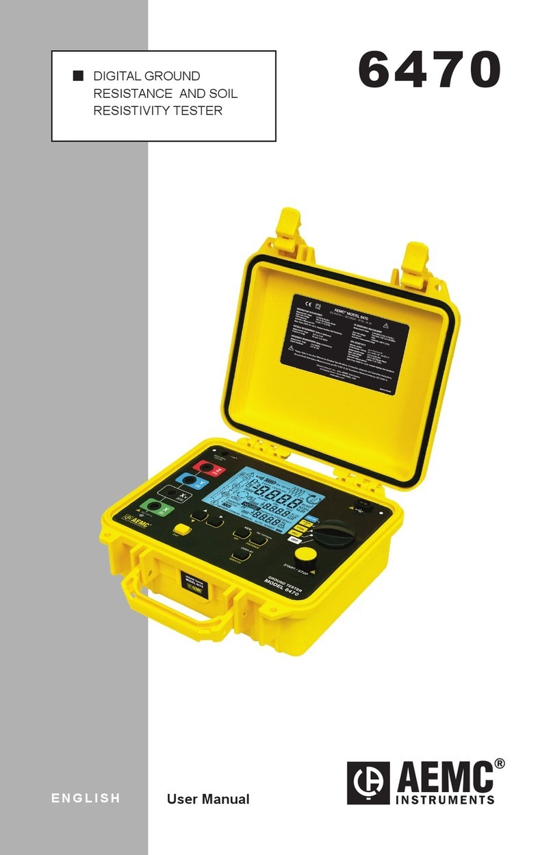
AEMC instruments 6470 User manual

AEMC instruments

AEMC instruments 6470 User manual

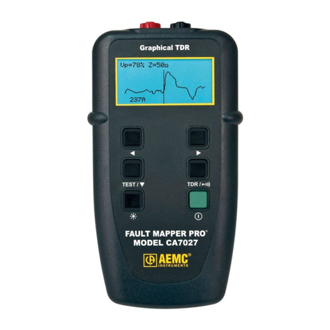
AEMC instruments CA7027 User manual

AEMC instruments

AEMC instruments CA7027 User manual

AEMC instruments 6471 User manual

AEMC instruments

AEMC instruments 6471 User manual

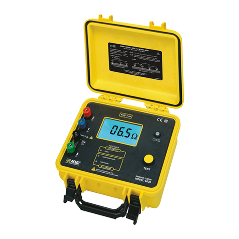
AEMC instruments 4620 User manual

AEMC instruments

AEMC instruments 4620 User manual

AEMC instruments 8510 User manual

AEMC instruments

AEMC instruments 8510 User manual

AEMC instruments 6240 User manual

AEMC instruments

AEMC instruments 6240 User manual

AEMC instruments 6416 User manual

AEMC instruments

AEMC instruments 6416 User manual

AEMC instruments 6418 User manual

AEMC instruments

AEMC instruments 6418 User manual

AEMC instruments GROUNDFLEX 6474 User manual

AEMC instruments

AEMC instruments GROUNDFLEX 6474 User manual

AEMC instruments 6422 User manual

AEMC instruments

AEMC instruments 6422 User manual

AEMC instruments 2121.04 User manual

AEMC instruments

AEMC instruments 2121.04 User manual

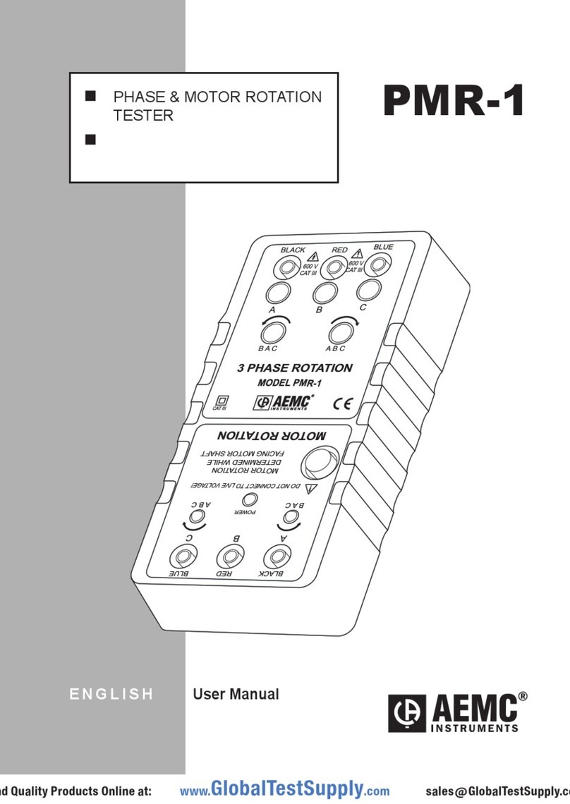
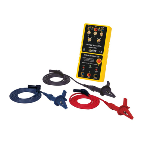
AEMC instruments PMR-1 User manual

AEMC instruments

AEMC instruments PMR-1 User manual

Popular Test Equipment manuals by other brands

Renkforce 6895N operating instructions

Renkforce

Renkforce 6895N operating instructions

Agilent Technologies 54831A User's quick start guide

Agilent Technologies

Agilent Technologies 54831A User's quick start guide

Supelco Reflectoquant RQflex 20 operating manual

Supelco

Supelco Reflectoquant RQflex 20 operating manual

Baker Instrument Company D12R user manual

Baker Instrument Company

Baker Instrument Company D12R user manual

LeCroy WaveMaster 8 Zi Getting started manual

LeCroy

LeCroy WaveMaster 8 Zi Getting started manual

Keysight Technologies DP001 A Series user guide

Keysight Technologies

Keysight Technologies DP001 A Series user guide

Rohde & Schwarz AMU200A operating manual

Rohde & Schwarz

Rohde & Schwarz AMU200A operating manual

Tektronix TBS2000 Series Safety and installation instructions

Tektronix

Tektronix TBS2000 Series Safety and installation instructions

RuoShui 01+ Operation manual

RuoShui

RuoShui 01+ Operation manual

Omega BB703 user guide

Omega

Omega BB703 user guide

Fluke ScopeMeter 190-502 user manual

Fluke

Fluke ScopeMeter 190-502 user manual

Fluke i400 Calibration information

Fluke

Fluke i400 Calibration information

Owon VDS6104P user manual

Owon

Owon VDS6104P user manual

Hioki 3280-10 instruction manual

Hioki

Hioki 3280-10 instruction manual

THORLABS PTR302 user guide

THORLABS

THORLABS PTR302 user guide

Tektronix TriMode P7504 Quick start user manual

Tektronix

Tektronix TriMode P7504 Quick start user manual

Seismic Source DAQlink III user manual

Seismic Source

Seismic Source DAQlink III user manual

Dynisco SC170 Installation and operation

Dynisco

Dynisco SC170 Installation and operation

manuals.online logo
manuals.online logoBrands
  • About & Mission
  • Contact us
  • Privacy Policy
  • Terms and Conditions

Copyright 2025 Manuals.Online. All Rights Reserved.