Starrett S-700 Series User manual

MAKE A GRAND ENTRANCE
INSTALLATION GUIDE
SERIES S-700
If you think anything is missing, or
there is damage, alert Spitfire Doors
or your supplier immediately.
1. If you are replacing an existing door, please measure
the new door to make sure it ts before removing
the old door and make sure that the threshold height
and or cill and packers allow enough clearance to
open the new door when tted.
2. Please store your new door in a clean and obstacle
free area before installing
3. Make sure the aperture is level and as plumb as
possible before starting to install
4. REMEMBER – A SINGLE S-700 SERIES DOOR
WILL WEIGH AT LEAST 120KG AND IS A
MULTIPLE PERSON LIFT!
Key Points:
We recommend that your door is
installed by a recognised Spitfire Partner.

1. 1.8m Spirit level
2. 0.6m Spirit level
3. 8 Winbags or similar inatable xing aids
4. Timber wedges
5. Percussion drill and 6mm SDS drill bits
6. Extra Long 300mm Flat Head Screwdriver
7. PH2 and PZ2 screwdriver bits
8. Starx direct-x masonry anchors
minimum 150mm long
9. Gun grade expanding polyurethane foam
and applicator
SUGGESTED
TOOLS REQUIRED
Installation
Preparation
Installing an S-700 door, requires 3-4 people to lift the
door into place and to hold it in position whilst adjusting,
during installation.
Carefully unwrap your S-700 pivot door and dispose of the
timber sub-frame.
It would be a good idea to protect your door with a blanket
or dust sheet prior to installing, as conditions on site are
seldom perfect.
Keep your door and all components away from hazardous
materials like lime, cement or paint.
Cleaning door
after installation
• Surfaces should be only cleaned with neutral
cleaning agents.
• Spitfire sells specialist aluminium cleaner in
aerosol form.
• Use warm soapy water in a ratio of 5% liquid soap
and 95% water and simply wipe down with a damp
cloth. Do not use abrasive or aggressive cleaners,
bleach or other chlorine based cleaners.

Installation
Determine the finished floor level of your building because
your Spitfire Series 700 threshold sits at floor level. There is
only 25mm of cover between the bottom of the door sash
and the threshold.
- Unlock your door and open it to 90 degrees.
- On the inside of the frame, you will see the slotted top pin
retracting screw. (Image 1)
- Unwinding the screw will retract the top pin into the outer
frame. (The screw will stop unwinding after a few turns)
(Image 2)
Beware the door sash will weigh circa 120 KG
- Now tilt the sash towards the keep side and lift the sash off
the base plate.
- Carefully set the door sash to one side and cover it with a
dust sheet or similar.
- Check the diagonal dimensions of the door frame to ensure
the frame is square, then check vertical is plumb and fix
the brackets to the adjoining walling. As a general rule, we
recommend fixing 150mm in from each corner and then at
400mm intervals.
- Please peel back the frame gaskets and fix behind them.
We
suggest you remove the lock keep and fix behind the keep.
- Please always fix your door through the frame and do not use
fixing brackets.
- On the threshold, remove the rubber cover strip, fix
through, then replace cover strip.
NB. The outerframe must be COMPLETELY SQUARE AND
PLUMB before replacing sash on the base plate.
Please make sure the rotating pin has plenty of grease and is
spinning effortlessly.
Once the outer frame is secure, lift the door back into the frame
at 90 degrees.
Align the rotating pin with the sash and lean the door onto the
pin. You may need a few attempts to get the spacing right,
but you should feel the sash sliding onto the pin when aligned
correctly. (Image 4)
Image 1
Image 2
Image 3
Image 4
MAKE A GRAND ENTRANCE
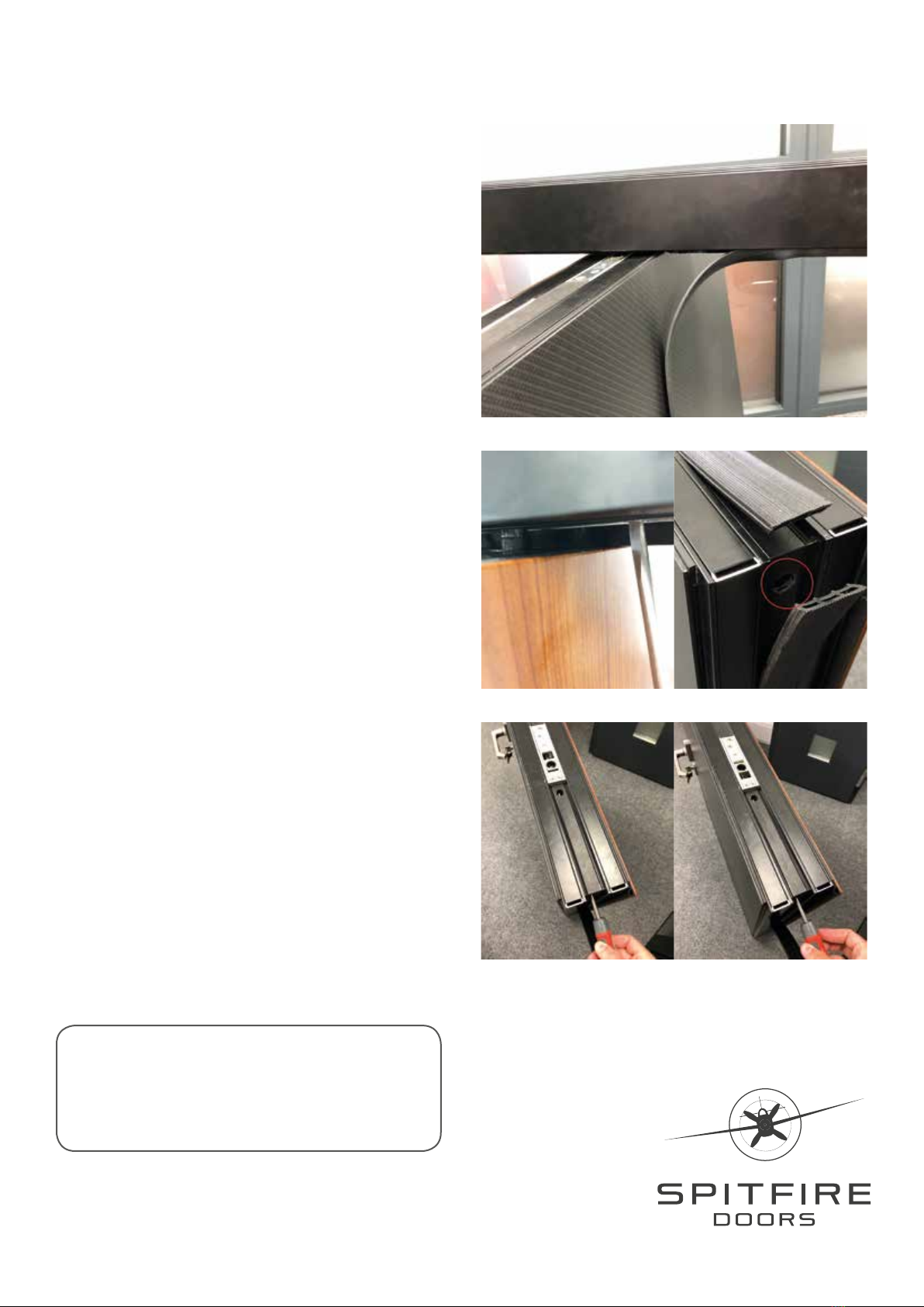
When the door is slotted into the baseplate, you will need to
sink the top pin back into the door sash to secure it in place.
- Removing the top outside gasket will give you better
visibility of the top pin. (Image 5)
- Bring the top pin in line with the opening on the sash and
screw the top pin into place until the top pin retracting
screw is fully wound back into place (Image 6)
- Carefully close the door against the frame and align the door
sash with the frame and check the shadow joint around the
door/frame junctions as this should be equal all the way
around with a 6mm gap (+/– 1mm). The door should close
and lock should engage without undue force. If the door is
mis-aligned or proud at any point, the frame may be twisted
and should be realigned before proceeding further.
- Check that the bottom of the door seals meet the threshold
to give a weatherproof seal.
- If necessary, adjust the position of the door with the
levelling screw that is located on the pivot side of the sash,
underneath the gasket. You will need to insert an extra long
flat head screw driver into the side of the door sash to reach
this screw. (Image 7)
PLEASE BE AWARE: You MUST remove/unwind the top
pin and tilt the sash onto its side when making the levelling
adjustment. Otherwise the full weight of the sash will have to
be moved by the levelling screw. Failing to do this will result
in permanent damage to the mechanism and a costly remake
sash could be required. Adjusting the screw clockwise will
lift the corner of the lock side, spinning the screw counter
clockwise will lower the sash corner. (Image 8 & 9)
Once the door is operating satisfactorily, seal the gap between
perimeter of the frame and the wall. Depending on the gap size
use either pre-formed sealant material (Compriband or similar),
silicone sealant or low expansion foam sealant. Always keep
the door in the closed position until the sealant has fully cured
to avoid any movement in the frame.
Installation
Image 5
Image 6 Image 7
Image 8 Image 9
If in doubt contact us on
01625 412 570
Other Starrett Tools manuals


Popular Tools manuals by other brands


Mafell
Mafell ZH 205 Ec Translation of the original operating instructions

Innova Electronic Corp.
Innova Electronic Corp. 3150e Quick reference guide

RED ROOSTER
RED ROOSTER RR-0315NS manual

Omer
Omer HR23 M8 Use, maintenance and spare parts manual

ULTIMATE SPEED
ULTIMATE SPEED KH 3017 Operation and safety notes

Performance Tool
Performance Tool W89220 owner's manual