Start italiana TOKHEIM Pro Gauge XMT-SI-485-LOG User manual
INSTALLATION
MANUAL
XMT-SI-485
XMT
-
SI
-
4
-
20mA
XMT-SI-RF
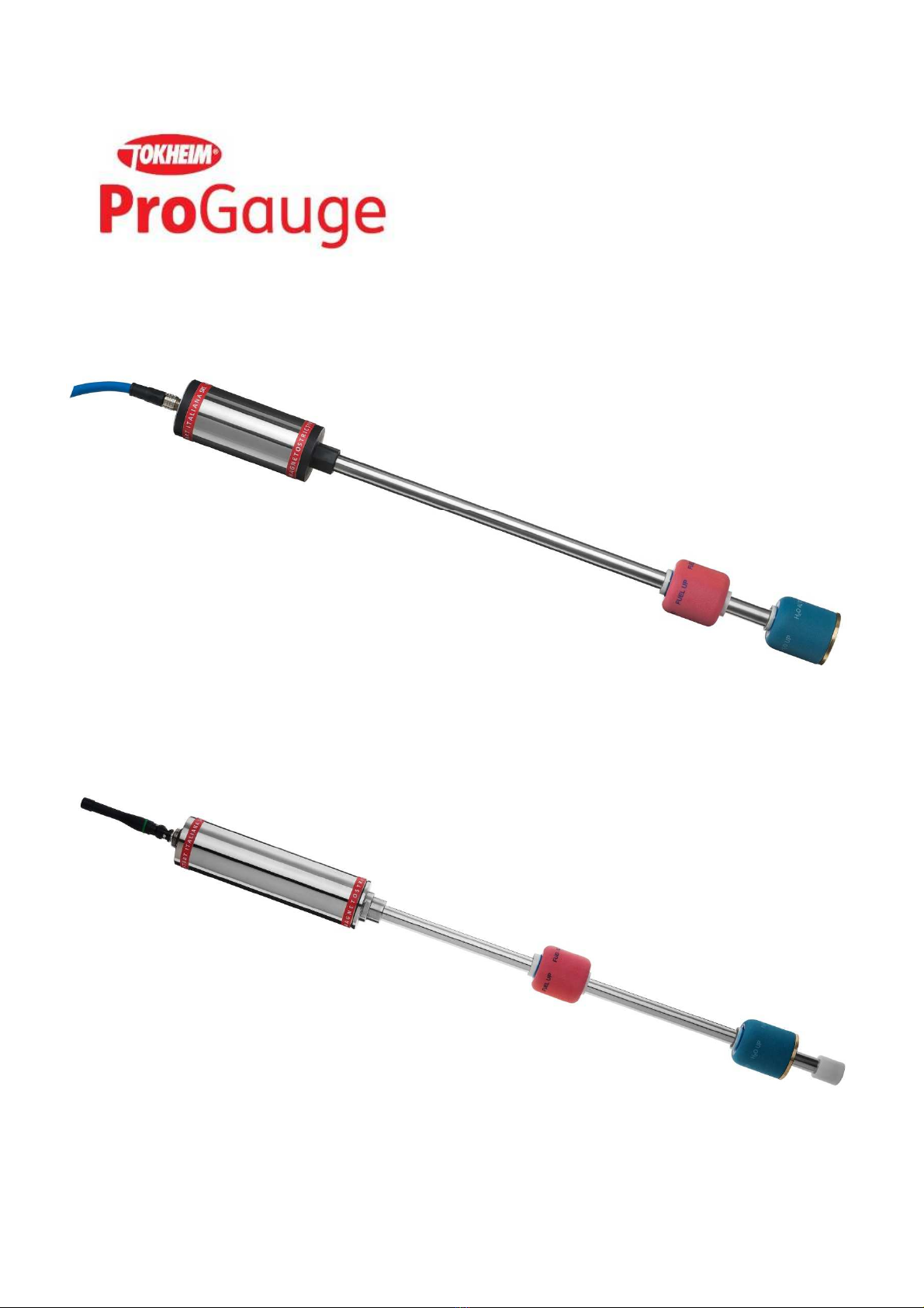
MAGNETOSTRICTIVE
I.S. PROBE
WIRELESS
I.S. PROBE
XMT-SI-485, XMT-SI-RF, XMT-SI 4-20mA, Bla kSeal rev.09 2017.03 - ENG
2
INDEX
INDEX .............................................................................................................................................................................................................................. 2
REVISION INDEX ........................................................................................................................................................................................................... 2
INTRODUCTION ........................................................................................................................................................................................................... 3
GENERAL WARNINGS ................................................................................................................................................................................................. 3
GENERAL INFORMATION........................................................................................................................................................................................... 4
TECHNICAL CHARACTERISTICS XMT-SI ................................................................................................................................................................. 5
WIRING OF THE CONNECTOR ................................................................................................................................................................................. 6
PRODUCT LABEL .......................................................................................................................................................................................................... 7
MECHANICAL INSTALLATION XMT-SI .................................................................................................................................................................... 8
EXAMPLE OF RISER PREPARATION FOR RF PROBES ......................................................................................................................................... 10
ELECTRICAL CONNECTION ...................................................................................................................................................................................... 13
XMT-SI-485 HOUSING OPENING AND CLOSURE ..............................................................................................................................................14
JUMPER SETTING ........................................................................................................................................................................................................14
MODEL XMT-SI-RF ...................................................................................................................................................................................................... 15
DIP-SWITCH PROGRAMMATION ............................................................................................................................................................................ 15
MODEL XMT-SI-485 ................................................................................................................................................................................................... 17
DIP-SWITCH PROGRAMMATION ............................................................................................................................................................................ 17
TRANSMISSION PROTOCOL .................................................................................................................................................................................... 17
LED BEHAVIOUR.......................................................................................................................................................................................................... 18
XMT-SI-485-LOG PROBE WITH MEMORY AND DATA LOGGER FUNCTIONALITY ..................................................................................... 19
DATA LOGGER PROTOCOL ...................................................................................................................................................................................... 19
BLACK SEAL VERSION ............................................................................................................................................................................................... 22
4-20MA VERSION ...................................................................................................................................................................................................... 23
ATEX CERTIFICATION AND NOTIFICATION ........................................................................................................................................................ 24
REVISION INDEX
This produ t omplies with EU Dire tive 20
1
2/
19
/
UE
.
The rossed-bin symbol fixed on the devi e indi ates that the produ t, at the end of its useful life, should be disposed of
separately from household waste, must be taken to a olle tion point for ele tri al and ele troni equipment.
Nota: Start Italiana Srl, in respe t of its quality duty may modify its produ tion and data shown into this manual. This
manual annot be opied, neither partially, without authorization.
DATA
REVISION
NUMBER
DESCRIPTION
Versione
Firmware
01
-
09
-
2014
05
GENERAL REVISION
23
-
09
-
2014
06
BLACK SEAL VERSION ADDED
30
-
04
-
2015
07
GENERAL UPDATES
02
-
2016
08
LED BEHAVIOUR EXPLANATION
06
-
2016
09
ADD THE 4
-
20mA MODEL PAGE
03
-
2017
09.E
MI
NOR CORRECTION
S

XMT-SI-485, XMT-SI-RF, XMT-SI 4-20mA, Bla kSeal rev.09 2017.03 - ENG
3
INTRODUCTION
This manual gives all the installation and use instru tions for XMT-SI level probes family.
GENERAL WARNINGS
•Before the installation and use of the equipment please arefully read the instru tions given into this manual.
•The manufa turer is not responsible of any possible operation not mentioned into this manual.
•Any failure or faulty operation would o ur to the equipment, please refer to the authorized personnel for maintenan e or dire tly
to the manufa turer.
•The manufa turer refuses all responsibility for any eventual injury and/or damage to things aused to the non-observan e of the
safety regulations.
•The assigned personnel is required to know all the safety regulations relative to the hereby des ribed equipment.
•Any doubt may o ur about the fun tioning of the equipment please refer to the authorized personnel for maintenan e or dire tly
to the manufa turer.
•Tampering releases the manufa turer from any responsibility in front of the ompetent authority.
•This produ t is used in fuel tanks and in hazardous areas for risk of explosion and fire. Subterranean leakages of the fuel tanks
may ause serious damages to environment and injury.
•If mixed with air, the flammable vapors may ause explosion. Hazardous areas may be originated therefore by the presen e of
gas or vapors.
•Explosions or fire may ause damages, even lethal.
•The magnetostri tive probe an be installed in hazardous areas.

XMT-SI-485, XMT-SI-RF, XMT-SI 4-20mA, Bla kSeal rev.09 2017.03 - ENG
4
GENERAL INFORMATION
The magnetostri tive level transmitters are based on the prin iple named Wiedemann effe t and enable ontinuous and highly
a urate reading of liquid’s level.
The XMT-SI level transmitter onsists of a mi ropro essor based ele troni ir uit pla ed inside one aluminium ase head and a
stainless steel shaft ontaining a wave guide pla ed inside the tank.
An high frequen y ele tri impulse is transmitted through the ele troni devi e. In the mat hing point with the magneti field
generated by the permanent magnet pla ed inside the float, a me hani impulse is generated thanks to the magnetostri tive torsional
strain. The me hani impulse spreads through the wave guide to the speed of sound up to the sensor pla ed in the measuring head. The
timing between the transmission of the going impulse and the return impulse exa tly defines the position of the floats.
XMT-SI family are high pre ision measure instrumentation whi h are suitable to measure produ t level, water level and
temperature in various type of underground and above ground tank, also pla ed in hazardous areas.
The XMT-SI family is intrinsi ally safe ertified for 0 Zone and through an intrinsi ally safety barrier an be onne ted to onsole
or PC positioned in a safety zone for having a omplete ontrol of the tank.
The following models are available:
XMT-SI-485 transmits data on the 485 bus. It an be onfigured for polling mode. It is externally powered by the ommuni ation bus.
XMT-SI-RF transmits data using a radiofrequen y transmission with variable frequen y depending on the level hanges inside the tank. It
is powered by a lithium battery positioned inside the probe and ertified also for intrinsi ally safety. In order to grant the
intrinsi ally safety of the transmitter, the battery must be repla ed only by another one.
XMT-SI-TTL transmits data using a TTL interfa e for OEM appli ations. The asso iated instrument must be ertified in ase it is ne essary
to install the produ t in a ertified zone.
XMT-SI-485-LOG transmits data on a 485 bus. It is onfigured for fun tioning in polling mode. Normally it is powered externally using a
ommuni ation bus. If the external power is dis onne ted, automati ally a battery pla ed inside allows to keep the
probe working and stores the level hanges in a non-volatile memory for subsequent download of the data possible
on re overy of the main supply.
XMT-SI-4-20mA transmits a 4-20mA urrent signal over 2 wires

XMT-SI-485, XMT-SI-RF, XMT-SI 4-20mA, Bla kSeal rev.09 2017.03 - ENG
5
TECHNICAL CHARACTERISTICS XMT-SI
Four types of interfa e are available:
RS 485 serial door for multipoint onne tion
•Power supply 12 VDC through an intrinsi ally safe barrier.
•Consumption <15 mA @ 12 Vd normal fun tioning
•Consumption < 200 uA @12 Vd in sleep mode fun tioning
•Conne tion able: hydro arbons resistant, suitable for underground pose with insulation 0,6-1KV, 2 shielded and twisted pairs,
se tion of the power able pair of at least 1mm2.
•Type of able supplied by Start Italiana: LiYstCYY INSULATION LEVEL 4 (0,6/1KV) - (2x0.25mm²) + 2x1.00mm² CEI 20-22II IEC
60332-3A ENI 00.181.00
•Maximum transmission distan e: up to 2 Km based on standard of RS485 interfa e.
RF interfa e:
•Internal power supply through an instrinsi ally safe battery 3.6V, 16Ah
•Low frequen y transmission to a re eiver lo ated in a safety zone.
•Consumption <15 mA @ 12 Vd normal fun tioning
•Consumption < 200 uA @12 Vd in sleep mode fun tioning
4-20mA interfa e
•Power supply 24 VDC through an intrinsi ally safe barrier.
•Signal 4 to 20 mA over 2 wires only 1 produ t float
TTL Interfa e for OEM appli ations:
•Power supply 5Vmax, 100mA max from ertified external devi e
•Serial transmission TTL levels
•Maximum distan e: 3 mt, ompatible with TTL signals
RS485-LOG serial door for multipoint onne tion with internal battery for storage of data in ase of missing external power supply or
polling
•Power supply 12 VDC through an intrinsi ally safe barrier.
•Consumption <15 mA @ 12 Vd normal fun tioning
•Consumption < 200 uA @12 Vd in sleep mode fun tioning
•Internal power supply through an instrinsi ally safe battery 3.6V, 16Ah
•Conne tion able: hydro arbons resistant, suitable for underground pose with insulation 0,6-1KV, 2 shielded and twisted pairs,
se tion of the power able pair of at least 1mm2.
•Type of able supplied by Start Italiana: LiYstCYY INSULATION LEVEL 4 (0,6/1KV) - (2x0.25mm²) + 2x1.00mm² CEI 20-22II IEC
60332-3A ENI 00.181.00
•Maximum transmission distan e: up to 2 Km based on standard of RS485 interfa e.
For all the types the measurement hara teristi s are:
•Ele troni s based on a Mi ropro essor
•Support telediagnosti s and telemaintenan e
•Possibility to onfigure remotely the fun tional parameters
•In ase of maintenan e the internal part of the sensor (wave guide) an be removed without degas the tank, espe ially useful
for LPG appli ations where the tanks are in pressure.
•Tank onne tion:
-Not needed if probe is inserted into a riser with internal diameter 2”
-2” sliding onne tion as standard.
XMT-SI-485, XMT-SI-RF, XMT-SI 4-20mA, Bla kSeal rev.09 2017.03 - ENG
6
-Other type of optional onne tions under request (nippled fixed, flanged, …)
•Stainless steel ase, IP68.
•Probe shaft Stainless Steel AISI 304 / 316
•Measurement range: from 200 mm. to 12.500 mm.
•Maximum me hani al length: 13.000 mm.
•Data transmitted:
-Produ t level in 0.01 mm
-Water level in 0.01 mm
-Medium temperature dete ted through digital temperature sensor pla ed along the probe shaft (max 5)
•Measurement a ura y: +/- 0,5 mm.
•Measurement resolution: +/- 0,05 mm.
•Temperature a ura y: +/- 0,2°C (up to 5 temperature sensor option is available for stati leak test)
•Approvals :
-OIML-R85 for fixed appli ations
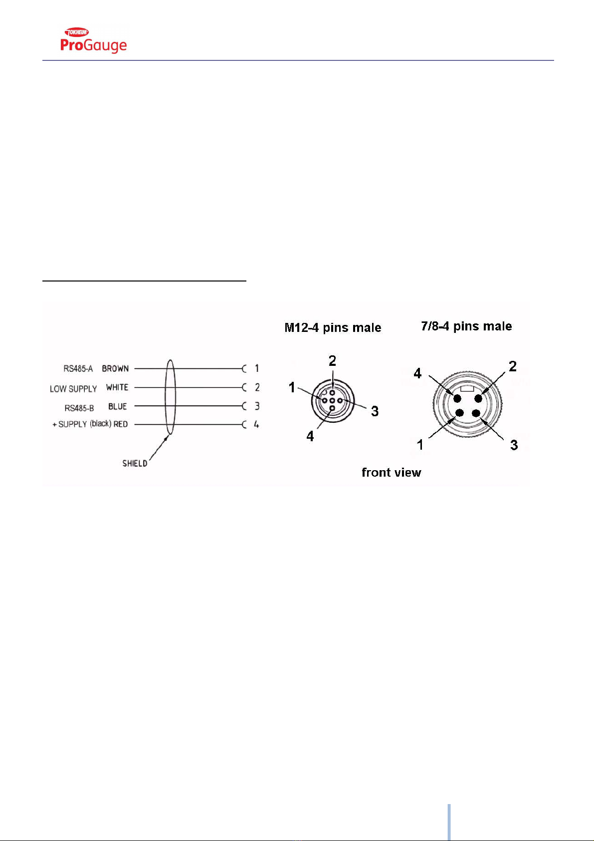
WIRING OF THE CONNECTOR
T= - 40°C + 85°C
Ui = 16V Ii = 125mA
Ci = tras urabile/negligible
Li = tras urabile/negligible
The serial number is unique and orresponds to the probe address for the onsequent onfiguration into the ontrol ele troni s.

XMT-SI-485, XMT-SI-RF, XMT-SI 4-20mA, Bla kSeal rev.09 2017.03 - ENG
7
PRODUCT LABEL
XMT-SI-485
START ITALIANA S.r.l. - Italy
Via Pola, 6 - 20813 Bovisio Mas iago (MB)
0722 CEC 09 ATEX 131 rev.4
II 1G Ex ia IIB T4 Ga
II 1D Ex ta IIIC T135°C Da IP66/68 FISCO Field devi e Exia IIC T4
Tipo/Type: XMT-SI-485
Anno/Year: (20)XX
S.N.: XXXXX
T= - 40°C + 85°C
Ui = 16V li = 125mA
Ci = tras urabile/negligible
The serial number is unique and orresponds to the probe address for the onsequent onfiguration into the ontrol ele troni s.
XMT-SI-RF
START ITALIANA S.r.l. - Italy
Via Pola, 6 - 20813 Bovisio Mas iago (MB)
0722 CEC 09 ATEX 131 rev.4
II 1G Ex ia IIB T4 Ga
II 1D Ex ta IIIC T135°C Da IP66/68 FISCO Field devi e Exia IIC T4
Tipo/Type: XMT-SI-RF
Anno/Year: (20)XX
S.N.: XXXXX
T= - 40°C + 85°C
Lithium battery inside
The serial number is unique and orresponds to the probe address for the onsequent onfiguration into the ontrol ele troni s.

XMT-SI-485, XMT-SI-RF, XMT-SI 4-20mA, Bla kSeal rev.09 2017.03 - ENG
8
XMT-SI-4-20mA
START ITALIANA S.r.l. - Italy
Via Pola, 6 - 20813 Bovisio Mas iago (MB)
0722 CEC 09 ATEX 131 rev.4
II 1G Ex ia IIB T4 Ga
II 1D Ex ta IIIC T135°C Da IP66/68 FISCO Field devi e Exia IIC T4
Tipo/Type: XMT-SI-4-20mA
Anno/Year: (20)XX
S.N.: XXXXX
T= - 40°C + 85°C
Ui = 28V li = 100mA
Ci = tras urabile/negligible
MECHANICAL INSTALLATION XMT-SI
The XMT-SI magnetostri tive level probe is supplied into arton pa kages for station, pa ked singularly or up to 7 pie es. We
re ommend to he k pa king integrity.
When removing the original pa king please pay attention not to bend the stainless steel men-hole reminding that it is an
ele troni devi e.
The standard version of level probe XMT-SI is supplied with a sliding 2” gas M fitting or without fitting in ase of installation
inside a prote tion riser.
The sliding 2” gas M fitting and the assembled floats enable to easily shift into 2” onne tion. This makes the probe insertion
inside the tank easier, and it means that no part of the probe must be disassembled.
The probe must be pla ed as mu h as possible in the enter of the tank, in verti al position, and it must be far from the produ t
loading. The shaft inside the tank must not be either folded or blended and must not be subje ted to impa t or stress.
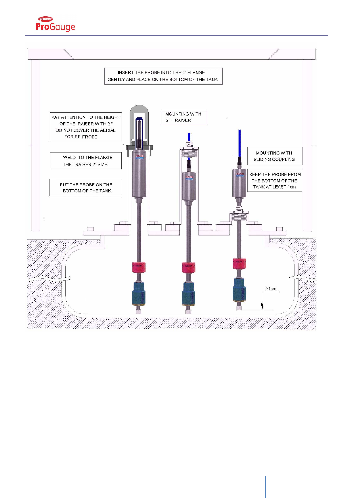
The probe must be mounted keeping the head as mu h high as possible to avoid its flooding. Insert the probe in the 2” G-F
tank gate and make it rea h the floor with are then raise it of at least 10mm, this will avoid bending of the shaft in ase loading operation
make tank deforming.
Before introdu ing the probe inside the tank please he k the orre t floats positioning and lamping of the plasti shaft end
ap. In order to allow to the floats to identify orre tly water and fuel levels, it is important to verify that the plasti shaft end ap has been
lamped on the shaft on the orre t side.
Conne t probe able to the plant as des ribed afterwards.
Conne t sensors as des ribed into the “Ele tri al onne tion” se tion.
XMT-SI-485, XMT-SI-RF, XMT-SI 4-20mA, Bla kSeal rev.09 2017.03 - ENG
9

XMT-SI-485, XMT-SI-RF, XMT-SI 4-20mA, Bla kSeal rev.09 2017.03 - ENG
10
EXAMPLE OF RISER PREPARATION FOR RF PROBES
•Use galvanized pipe with internal diameter of mm. 52 (weld pipe);
•Cut the orre t size in order that on e s rewed the riser goes to over the probe head leaving ompletely free the transmitting-
re eiving antenna;
•Seal the thread at the side flange with hemp and sealant to ensure tightness of the tank;
•After installation of the riser, pla e arefully the wireless probe into the tank;
•After positioning into the tank, tighten the PA antenna prote tion supplied with the probe;

XMT-SI-485, XMT-SI-RF, XMT-SI 4-20mA, Bla kSeal rev.09 2017.03 - ENG
11
•Finally tighten the PA 2” prote tion supplied with the wireless probe applying a sealant produ t (Lo tite, et .) between the male
riser and female, paying attention not to for e too mu h the s rewing.
XMT-SI-485, XMT-SI-RF, XMT-SI 4-20mA, Bla kSeal rev.09 2017.03 - ENG
12
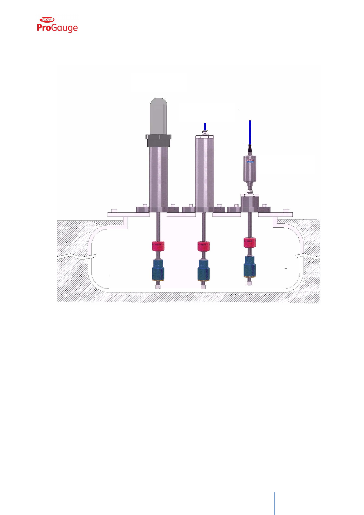
Please follow the above pro edures if probes are wired. The only differen e is that the length of the riser must over the total
length of the probe, and a ap with a able gland must be s rewed to allow the exit of the onne tion able.
Please refer to RF re eiver te hni al manual supplied with the produ t for the installation pro edure.
XMT
-
SI
-
RF
WITH RISER
XMT
-
SI
-
485
WITH RISER
XMT
-
SI
-
485
WITHOUT RISER

XMT-SI-485, XMT-SI-RF, XMT-SI 4-20mA, Bla kSeal rev.09 2017.03 - ENG
13
ELECTRICAL CONNECTION
In ase of hydro arbon vapor please use anti-sparks tools.
•The installation must be realized by spe ialized people
•Respe t the safety rules
•Read arefully the instru tions provided into this manual
•The manufa turer is not responsible for any damage and/or supplementary osts due to the missing respe t of the supplied
instru tions.
The probe is supplied with 1.5 meters of able onne ted through 7/8” onne tor to the probe head.
This able must be onne ted to the ba k bone using a jun tion box.
It is re ommended to use a jun tion box IP68 for intrinsi ally safety onne tion supplied by Start Italiana under request.
In a typi al ele tri al onne tion all the probes are onne ted in parallel. Normally all the bus onne tions must be as ading to grant
ertain transmission distan es. In ase of servi e stations distan es are extremely redu ed, bran hes no longer than 50 meters, and in this
ase it is a eptable to have a star type wiring.
Please use if possible Start Italiana jun tion boxes IP68 and omplete of internal terminal box.
The 4 wire onne tion able has always red (or bla k)-brown-blue and white olors.
Conne t to the terminal box the same olor type: red-red, white-white et . Panel ables have all to be onne ted in parallel as a fifth wire
and onne ted to the earth into the offi e using a prote ted ground tap whi h must not be shared with those of motors or power systems.
For onne tion and programming of the onsoles please refer to the manual provided together with every devi e.
The installation must be done in omplian e with CEI 64-8 and EN 60079-14 standards.
Use able ompliant with regulation in for e in the ountry of installation.
CEI 64-8 Ele tri al installations with nominal voltage not higher than 1000Va and 1500Vd
EN 60079-14 Classif.CEI 31-33 “Explosive atmospheres - Part 14: Ele tri al installations design, sele tion and ere tion”.
XMT-SI-485, XMT-SI-RF, XMT-SI 4-20mA, Bla kSeal rev.09 2017.03 - ENG
14
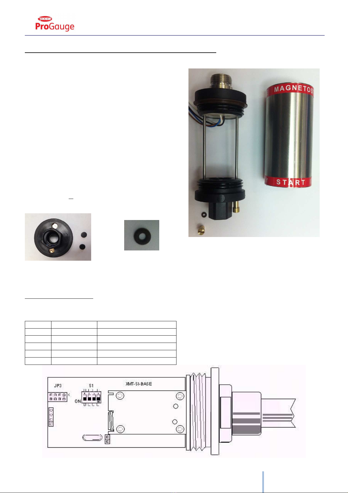
XMT-SI-485 HOUSING OPENING AND CLOSURE
The TOP and BOTTOM caps can be unscrewed. This is valid for the latest
revision of probes.
For older revision the fixing caps is different. Take a look at the bottom cap.
If ou are able to locate the brass screws in the bottom cap then ou have
to proceed as following:
PLEASE PAY ATTENTION NOT TO LOOSE OR DAMAGE ANY OF THE
COMPONENTS DISMOUNTED.
1. Remove the bla k Viton aps whi h over the s rews fixed on
the bottom ap of the housing (Pi ture 1)
2. Remove the brass s rews
3. Pay attention not to lose the O-ring (Pi ture 2)
4. Extra t the housing keeping the top onne tor, take are about
the ele troni s inside the housing
5. On e the Jumper setting has been ompleted as explained
below, assemble again the housing, paying attention to fix
orre tly all the omponents that have been previously
dismounted.
JUMPER SETTING
The meaning of the Jumpers is listed below. Jumpers are read during startup of the devi e. Every hange made when the devi e
is swit hed on won’t be onsidered. It is ne essary to swit h off and restart again the devi e so that the hanges are applied.
Jumper nr
INSERTED
REMOVED
1
1 FLOAT
2 FLOATS
2
Diagnosti mode
NORMAL mode (leave in this way)
3
For Wired probe
For RF probe
4
Sele t proto ol n. 1
Sele t proto ol n. 2
Pi ture
3
Pi ture 1
Pi ture 2
XMT-SI-485, XMT-SI-RF, XMT-SI 4-20mA, Bla kSeal rev.09 2017.03 - ENG
15
MODEL XMT-SI-RF
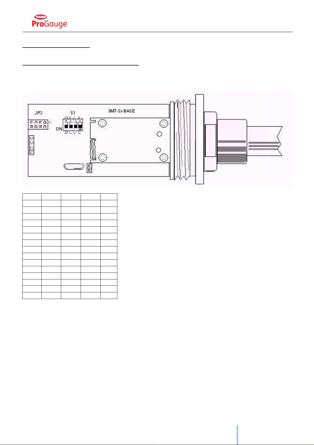
DIP-SWITCH PROGRAMMATION
There are several operation modes that an be sele ted through the internal DIP-Swit h. These operation modes an be applied
to RF probes. The operation mode defined will amend the life battery duration. Below is a table whi h gives the information on the
estimated life battery referred to the sele ted operation mode.
Radiofrequen y probes use a frequen y of 169,4Mhz, transmit on hannel 5 (169,468 MHz) power 200mW.
DIPSW1
DIPSW2
DIPSW3
DIPSW4
MODE
OFF
OFF
OFF
OFF
OP1
ON
OFF
OFF
OFF
OP2
OFF
ON
OFF
OFF
OP3
ON
ON
OFF
OFF
OP4
OFF
OFF
ON
OFF
OP5
ON
OFF
ON
OFF
OP6
OFF
ON
ON
OFF
OP7
ON
ON
ON
OFF
OP8
----
----
----
----
----
ON
ON
OFF
ON
OP12
OFF
OFF
ON
ON
OP13
ON
OFF
ON
ON
OP14
OFF
ON
ON
ON
OP15
ON
ON
ON
ON
OP16
DIP-Swit h are read during startup of the devi e. Every hange made when the devi e is swit hed on won’t be onsidered. It is
ne essary to swit h off and restart again the devi e so that the hanges are applied.
•OP1: wake up probe every 1 minute (Default setting)
•OP2: wake up probe every 2 minute
•OP3: wake up probe every 4 minute
•OP4: wake up probe every 5 minute
•OP5: wake up probe every 10 minute
•OP6: not a tive, don’t set
---------------------------------------------------
•OP11: not a tive, don’t set
•OP12: wake up probe every 30 se onds
•OP13: wake up probe every 20 se onds
•OP14: wake up probe every 15 se onds
•OP15: wake up probe every 10 se onds
•OP16: wake up probe every 5 se onds

XMT-SI-485, XMT-SI-RF, XMT-SI 4-20mA, Bla kSeal rev.09 2017.03 - ENG
16
Normally the probe is in sleeping mode in order to optimize the life battery duration.
At the set time the probe wakes up and makes the measure. If the measure of the produ t or of the water has a differen e of +/-1
mm ompared to that previously measured, the probe transmits the measure via radio or via able, otherwise it returns in sleeping mode.
In any ase after 10 minutes of non-transmission, the probe transmits the data even if they are un hanged to avoid the time-out of
the system. This has to be onsidered as an heart-beat for the re eiver. The re eiver should a tivate a non-rx alarm after 1 hour of
transmission absen e.
At power up:
During the probe installation open the housing of the probe to onne t the battery to the ele troni board, be ause the probe
is supplied with battery dis onne ted to preserve the harge until the use of the probe.
If the operation mode defined is between 1 and 5 after power up, the probe transmits data every 5 se onds for 24 hours, after
that the probes goes into the set operation mode.
This allow to he k the signal during the installation without waiting the programmed sleeping time.
This fun tion won’t be available if the hosen operation mode is between 12 and 16.
TIME LIFE BATTERY ESTIMATION FOR RF PROBES DEPENDING ON THE OPERATION
MODE DEFINED
OP MODE
Transmission every
x
minutes
Years of duration of the battery
1
1
3
2
2
3.5
3
4
4
4
5
4,5
5
10
5
----
----
----
12
30 se
1,3
13
20 se
0,9
14
15 se
0,7
15
10 se
0,5
16
5 se
0,3
These data are al ulated onsidering the worst onditions, assuming that for example the probe is programmed to transmit
every minute and effe tively it transmits every minute. Indeed the probe will not transmit if there is not a differen e of at least 1 mm, so
the life battery will be higher than that shown into the above table.
These data are al ulated based on a 16.5 Ah battery. Use only battery supplied by Start Italiana sin e this is an Intrinsi ally Safe
ertifi ated devi e and the supplied batteries satisfy the requirements. If another type of battery is used the Intrinsi ally Safe ertifi ation
is ompromised and Start Italiana won’t be responsible in ase any failure o urs.
XMT-SI-485, XMT-SI-RF, XMT-SI 4-20mA, Bla kSeal rev.09 2017.03 - ENG
17
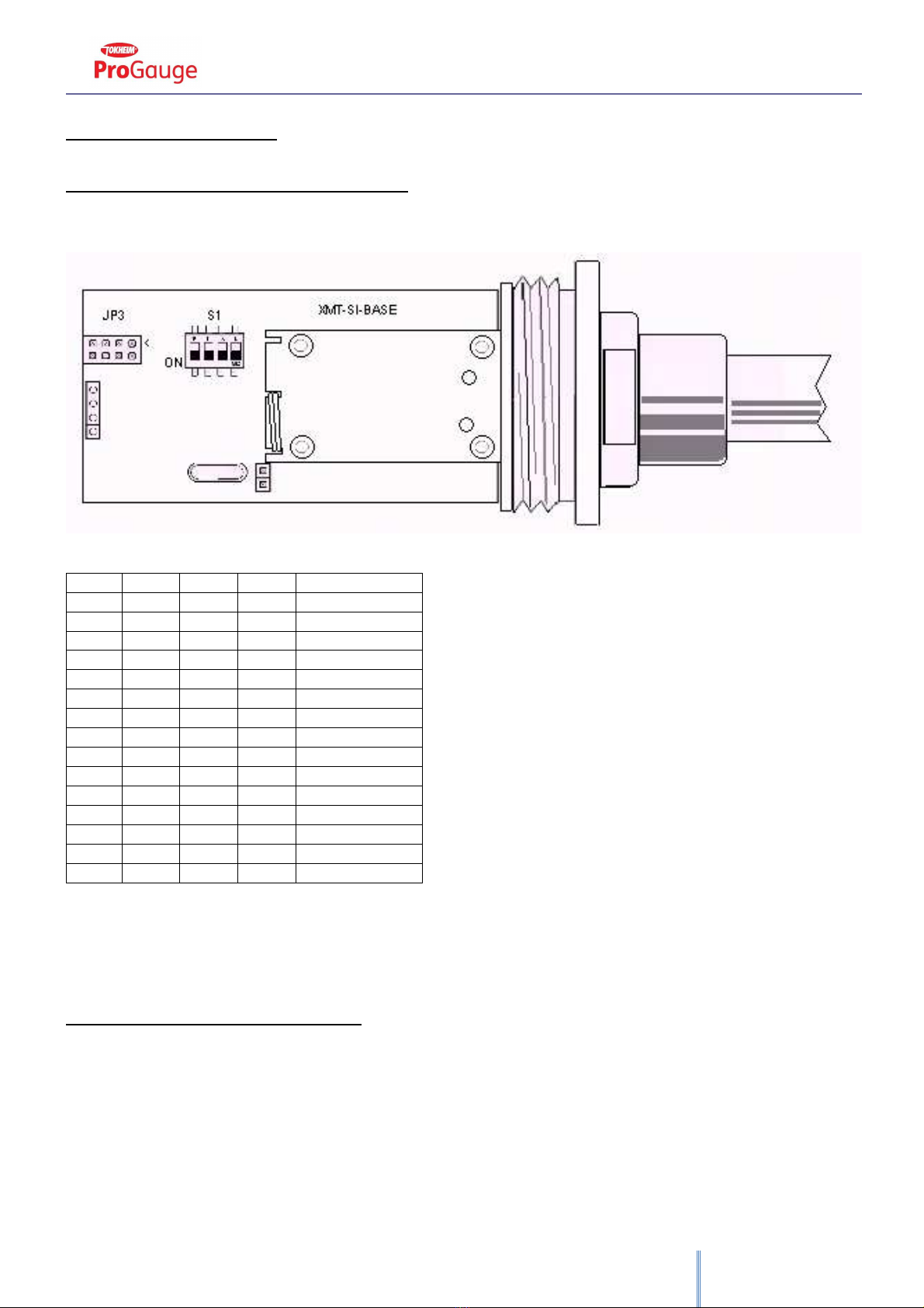
MODEL XMT-SI-485
DIP-SWITCH PROGRAMMATION
For this model it is possible to set an address between 1 and 15 in ase it would not be possible to use the addressed defined
into the memory, whi h oin ides with the serial number.
DIPSW1
DIPSW2
DIPSW3
DIPSW4
ADDRESS
OFF
OFF
OFF
OFF
MEMORY ADDRESS
ON
OFF
OFF
OFF
1
OFF
ON
OFF
OFF
2
ON
ON
OFF
OFF
3
OFF
OFF
ON
OFF
4
ON
OFF
ON
OFF
5
OFF
ON
ON
OFF
6
ON
ON
ON
OFF
7
----
----
----
----
----
ON
ON
OFF
ON
11
OFF
OFF
ON
ON
12
ON
OFF
ON
ON
13
OFF
ON
ON
ON
14
ON
ON
ON
ON
15
DIP-Swit h are read only at startup of the devi e.
Every hange made when the devi e is swit hed on won’t be onsidered. It is ne essary to swit h off and restart again the devi e
so that the hanges are applied.
TRANSMISSION PROTOCOL
Proto ol valid for XMT-SI-485, XMT-SI-485-LOG and TTL probes in polling mode.
Do not use this proto ol for RF probes.
Transmission parameters
•Speed: 9600 bps
•Parity: none
•Data bit: 8
•Stop bit: 1
•Flow ontrol: none

XMT-SI-485, XMT-SI-RF, XMT-SI 4-20mA, Bla kSeal rev.09 2017.03 - ENG
18
Using this setting the probe is not pla ed in sleeping mode but it is always a tive re eiving all the data transmitted on the bus and
answering only when a message is oming on its address.
Two different replies are available in order to grant ompatibility with previous proto ols.
Jumper nr
INSERTED
REMOVED
1
1
FLOAT
2
FLOATS
2
Diagnosti mode
Normal mode
(
don’t hange it
)
3
Polling Mode
Push mode
4
Pro otol sele tion answer 1
Proto ol sele tion answer 2
Command for data reading:
M[address]CrLf
Reply nr.1:
00348=0=+216=03722=0038=241
address=status=temperature in 10th of degree=produ t in 10th of mm=water in mm= he ksum
Reply nr.2:
00348N0=+217=00682.84=00073.22=098
address=status=temperature in 10th of degree=produ t in mm=water in mm= he ksum
Che ksum al ulation:
ASCII sum from the beginning up to the last one = in luded module 255.
Status:
0 = OK
1 probe unable to do the measure, he k number of floats inserted with referen e to the jumper setting, the orientation, he k if the shaft
is bended and if there is presen e of humidity inside the probe.
LED BEHAVIOUR
Inside the probe there are 2 leds:
GREEN:
If flash rapidly the probe is working fine
If flash slowly the probe is not able to dete t the float ( auses: float missing, float up-side down, probe bended, probe damaged)
RED:
Refle ts the serial ommuni ation:
If RED is OFF: no data are arriving on the serial ommuni ation RS485 port
If RED is ON: serial ommuni ation is arriving but probe is not demanded with its address
If RED is ON and then goes to OFF:
or 3 se s of timeout is passed without any serial ommuni ation
or the probe has been addressed and it is replying
The RED behavior depends on the polling y le and polling frequen y, and depends on how many probes are installed on the same bus.

XMT-SI-485, XMT-SI-RF, XMT-SI 4-20mA, Bla kSeal rev.09 2017.03 - ENG
19
XMT-SI-485-LOG PROBE WITH MEMORY AND DATA LOGGER
FUNCTIONALITY
WHAT HAPPENS IF POWER SUPPLY GOES OFF?
PROBE CONTINUES TO WORK AND STORE MOVEMENT DATA
WHAT HAPPENS IF POLLING IS DEACTIVATED OR DATA POLLING IS LOST?
PROBE CONTINUES TO WORK AND STORE MOVEMENT DATA
This model belongs to the XMT-SI-485 family with data logger fun tionality whi h is normally a tivated when external power supply goes
off and data polling is lost.
Probe works normally when external power supply is present, in polling mode, and onne ted to RS485 line. When external power supply
is missing, the internal battery is automati ally onne ted to the ele troni through an additional board of battery management.
The following a tions are performed:
•Start a minute ounter set at 0.
•Store the mm value measured at this time.
•Goes in power down mode.
•Every minute it wakes up, measures the level and he ks if there is a differen e of +/-1 mm ompared to the previous
measure. If major it stores the data.
•Returns in power down mode until the next minute.
•This ontinues until the external supply is missing.
•When external supply returns there is up to 1 minute of laten y before the probe is able to reply, be ause it must go out of
power down mode.
The same pro edure happens when polling is missing for more than 1 onse utive minute.
The maximum apa ity of event re orded is 3968. Supposing that there is one re ord every 10 minutes as average the logger time is
around 27 days. After that the newer will delete the older.
With this fun tionality, even if the power supply is dis onne ted by the probe or if data transmission is interrupted, it is possible to tra k
all the internal tank movement for a future downloading.
When the external power supply returns or data polling is re-a tivated, the probe returns to normal working suspending the logger data
re ording.
DATA LOGGER PROTOCOL
In this ase two additional ommands have been added in order to manage the logger data reading and deleting:
Data logger reading:
S[address]CrLf
Data logger delating:
Z[address]CrLf
Here is an example of the reply to S ommand:
S02102=00015=00237=00098=052
S02102=00014=00228=00098=051
S02102=00013=00225=00107=038
S02102=00012=00208=00115=037
S02102=00011=00204=00134=033
S02102=00010=00183=00155=041
S02102=00009=00173=00169=053

XMT-SI-485, XMT-SI-RF, XMT-SI 4-20mA, Bla kSeal rev.09 2017.03 - ENG
20
S02102=00008=00166=00159=053
S02102=00007=00155=00146=046
S02102=00006=00142=00136=040
S02102=00005=00135=00129=043
S02102=00004=00134=00115=036
S02102=00003=00002=00113=027
S02102=00002=00001=00102=023
S02102=00001=00000=00102=021
Meaning of the fields:
S[address]=[re ord_ ounter]=[minutes_from_starting_logging]=[mm]=[ hk]CrLf
Address: is the probe address
re ord_ ounter: is the progressive number of stored re ord
minutes_from_starting_logging: is related to the minute to whi h the stored re ord refers to. Minutes are al ulated starting from the
moment of power loss or after 1 minute of polling missing.
mm: level stored at that moment
Chk: ASCII sum of the entire frame in luded the last = mod 255.
At minute nr. 0 there is always the value in mm at the power off moment. At the last re ord transmitted there is always the value
of the measurement referred to the moment of the power on after return of external supply.
Looking at the above example from minute 2 to minute 134 the level has not hanged.
Expanding the above data it is possible to have the real movement of the level inside the tank registered during the power loss
or polling.
This graph has been generated expanding the above 15 re ords stored in 237 minutes of power loss.
NOTE: it is possible to send S ommand several times, will be always displayed the same results whi h are the logger ontent. The probe
will transmit re ords on onse utively but on groups of 16 re ords, it is ne essary to wait 1 se ond in order to let the re eiver system to
flush and elaborate the buffer. Then further 16 re ords will be send and so on. If during this delay time the probe is re eiving an ESC
ommand [0x1b] the transmission history will be stopped and probe goes to normal operation.
On e all the data have been read, it is suggested to perform Z ommand in order to delete the logger ontent. This is suggested
be ause in ase of another power loss the probe an store re ords starting from minute 0.
It happens the same on a probe that is not queried for a onse utive minute, also in this ase a new re ord session starts with
storage from minute 0.
0
20
40
60
80
100
120
140
160
180
1 14 27 40 53 66 79 92 105 118 131 144 157 170 183 196 209 222 235
mm
Time
Data logger result
Serie1
This manual suits for next models
4
Table of contents
Other Start italiana Measuring Instrument manuals


