Start italiana XMT-SI-485 User manual
INSTALLATION
MANUAL
XMT
-
SI
-
485
XMT
-
SI
-
RF
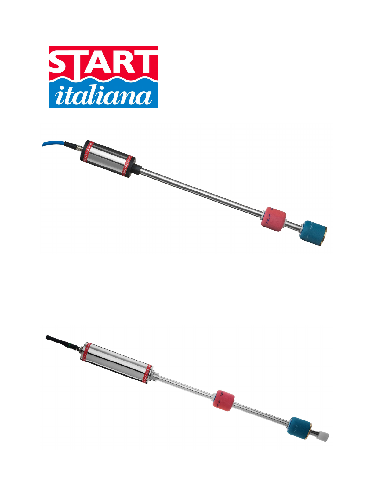
MAGNETOSTRICTIVE
I.S. PROBE
WIRELESS
I.S. PROBE

XMT-SI-485 – XMT-RF eng rev04 12/2013
2

XMT-SI-485 – XMT-RF eng rev04 12/2013
3
INDEX:
INTRODUCTION...…...….………………………………………………………………………………………...… pag. 4
GENERAL WARNINGS……...……………………………………………………………………………………… pag. 4
GENERAL INFORMATION…...……………………………………...……………………………………………...
pag. 5
TECHNICAL CHARACTERISTICS XMT-SI………………………………………………………………………. pag. 6
PRODUCT LABEL..………...……………………………………………………………………………………...... pag. 8
MECHANICAL INSTALLATION XMT-SI…………………………………………………………………………... pag. 9
EXAMPLE OF RISER PREPARATION FOR RF PROBES……...……………………………………………… pag.11
ELECTRICAL CONNECTION……………………………...……………………………………………………….. pag.14
JUMPER SETTING………………………..………….………………………………………………………………
pag.15
XMT-SI-RF MODEL…………….……..……………………………………………………………………………...
pag.16
XMT-SI-485 MODEL…………………………………………………………………………………………………. pag.18
XMT-SI-485-LOG – PROBE WITH MEMORY AND DATA LOGGER FUNCTIONALITY…………………… pag.20

XMT-SI-485 – XMT-RF eng rev04 12/2013
4
INTRODUCTION
This manual gives all the installation and use instructions for XMT-SI level probes family .
GENERAL WARNINGS
•Before the installation and use of the equipment please carefully read the instructions given into this manual.
•The manufacturer is not responsible of any possible operation not mentioned into this manual.
•Any failure or faulty operation would occur to the equipment, please refer to the authorized personnel for
maintenance or directly to the manufacturer.
•The manufacturer refuses all responsibility for any eventual injury and/or damage to things caused to the non-
observance of the safety regulations.
•The assigned personnel is required to know all the safety regulations relative to the hereby described
equipment.
•Any doubt may occur about the functioning of the equipment please refer to the authorized personnel for
maintenance or directly to the manufacturer.
•Tampering releases the manufacturer from any responsibility in front of the competent authority.
•This product is used in fuel tanks and in hazardous areas for risk of explosion and fire.
Subterranean leakages of the fuel tanks may cause serious damages to environment and injury.
•If mixed with air, the flammable vapors may cause explosion. Hazardous areas may be originated
therefore by the presence of gas or vapors.
•Explosions or fire may cause damages, even lethal.
•The magnetostrictive probe can be installed in hazardous areas.

XMT-SI-485 – XMT-RF eng rev04 12/2013
5
GENERAL INFORMATION
The magnetostrictive level transmitters are based on the principle named Wiedemann effect and enable continuous
and highly accurate reading of liquid’s level.
The XMT-SI level transmitter consists of a microprocessor based electronic circuit placed inside one aluminium
case head and a stainless steel shaft containing a wave guide placed inside the tank.
An high frequence electric impulse is transmitted through the electronic device. In the matching point with the
magnetic field generated by the permanent magnet placed inside the float, a mechanic impulse is generated thanks
to the magnetostrictive torsional strain. The mechanic impulse spreads through the wave guide to the speed of
sound up to the sensor placed in the measuring head. The timing between the transmission of the going impulse
and the return impulse exactly defines the position of the floats.
XMT-SI family are high precision measure instrumentation which are suitable to measure product level, water level
and temperature in various type of underground and above ground tank, also placed in hazardous areas.
The XMT-SI family is intrinsically safe certified for 0 Zone and through an intrinsically safety barrier can be
connected to console or PC positioned in a safety zone for having a complete control of the tank.
The following models are available:
XMT-SI-485 transmits data on the 485 bus. It can be configured for polling mode or push mode functioning based
on the needing. It is externally powered by the communication bus.
XMT-SI-RF transmits data using a radiofrequency transmission with variable frequency depending on the level
changes inside the tank. It is powered by a lithium battery positioned inside the probe and certified also for
intrinsically safety. In order to grant the intrinsically safety of the transmitter, the battery must be replaced only by
another one supplied by Start Italiana.
XMT-SI-TTL transmits data using a TTL interface for OEM applications. The associated instrument must be
certified in case it is necessary to install the product in a certified zone.
XMT-SI-485-LOG transmits data on a 485 bus. It is configured for functioning in polling mode. Normally it is
powered externally using a communication bus. If the external power is disconnected, automatically a battery
placed inside allows to keep the probe working and stores the level changes in a non-volatile memory for
subsequent download of the data possible on recovery of the main supply.

XMT-SI-485 – XMT-RF eng rev04 12/2013
6
TECHNICAL CHARACTERISTICS XMT-SI
Four types of interface are available:
RS 485 serial door for multipoint connection
•Power supply 12 VDC through an intrinsically safe barrier.
•Consumption <15 mA @ 12 Vdc normal functioning
•Consumption < 200 uA @12 Vdc in sleep mode functioning
•Connection cable: hydrocarbons resistant, suitable for underground pose with insulation 0,6-1KV, 2
shielded and twisted pairs, section of the power cable pair of at least 1mm2.
•Type of cable supplied by Start Italiana: LiYstCYY INSULATION LEVEL 4 (0,6/1KV) - (2x0.25mm²) +
2x1.00mm² CEI 20-22II IEC 60332-3A ENI 00.181.00
•Maximum transmission distance: up to 2 Km based on standard of RS485 interface.
RF interface:
•Internal power supply through an instrinsically safe battery 3.6V, 16Ah
•Low frequency transmission to a receiver located in a safety zone.
•Consumption <15 mA @ 12 Vdc normal functioning
•Consumption < 200 uA @12 Vdc in sleep mode functioning
TTL Interface for OEM applications:
•Power supply 5Vmax, 100mA max from certified external device
•Serial transmission TTL levels
•Maximum distance:3 mt, compatible with TTL signals
RS485-LOG serial door for multipoint connection with internal battery for storage of data in case of
missing external power supply or polling
•Power supply 12 VDC through an intrinsically safe barrier.
•Consumption <15 mA @ 12 Vdc normal functioning
•Consumption < 200 uA @12 Vdc in sleep mode functioning
•Internal power supply through an instrinsically safe battery 3.6V, 16Ah
•Connection cable: hydrocarbons resistant, suitable for underground pose with insulation 0,6-1KV, 2
shielded and twisted pairs, section of the power cable pair of at least 1mm2.
•Type of cable supplied by Start Italiana: LiYstCYY INSULATION LEVEL 4 (0,6/1KV) - (2x0.25mm²) +
2x1.00mm² CEI 20-22II IEC 60332-3A ENI 00.181.00
•Maximum transmission distance: up to 2 Km based on standard of RS485 interface.
For all the types the measurement characteristics are:
•Electronics based on a Microprocessor
•Support telediagnostics and telemaintenance
•Possibility to configure remotely the functional parameters
•In case of maintenance the internal part of the sensor (wave guide) can be removed without degas the
tank, especially useful for LPG applications where the tanks are in pressure.
•Tank connection:
-Not needed if probe is inserted into a riser with internal diameter 2”
-2” sliding connection as standard.
-Other type of optional connections under request (nippled fixed, flanged, …)
•Stainless steel case, IP68.
•Probe shaft Stainless Steel AISI 304 / 316

XMT-SI-485 – XMT-RF eng rev04 12/2013
7
•Measurement range: from 200 mm. to 12.500 mm.
•Maximum mechanical length: 13.000 mm.
•Data transmitted:
-Product level in 0.01 mm
-Water level in 0.01 mm
-Medium temperature detected through digital temperature sensor placed along the probe shaft
(max 5)
•Measurement accuracy: +/- 0,5 mm.
•Measurement resolution: +/- 0,05 mm.
•Temperature accuracy: +/- 0,2°C
-Certifications:
-CEC 09 ATEX 131 rev2 : II 1G Ex ia IIB T4 II 1D Ex tD A20 T135°C
-CEC 09 ATEX 131 rev3 : II 1G Ex ia IIB T4 Ga II 1D Ex t IIIC T135°C Da IP66/68
•Approvals :
-OIML-R85 for fixed applications
-OIML-R80 per mobile applications
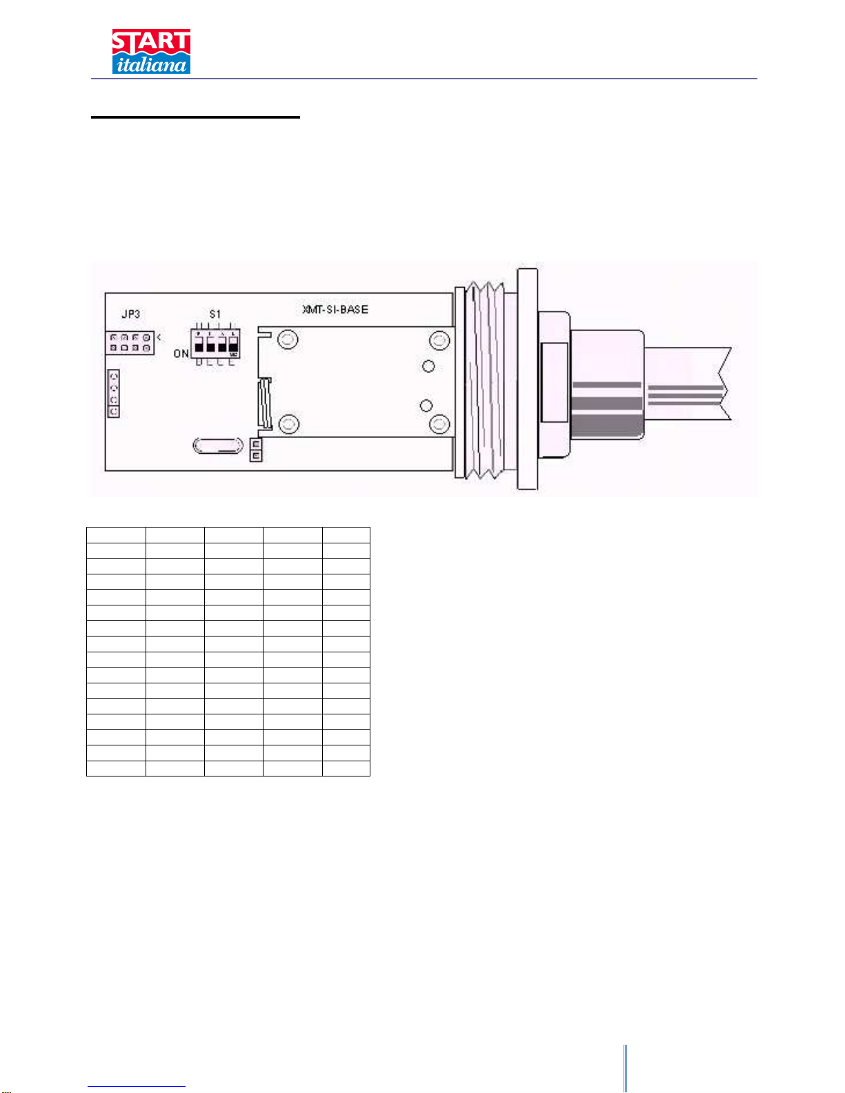
WIRING OF THE CONNECTOR

XMT-SI-485 – XMT-RF eng rev04 12/2013
8
PRODUCT LABEL
XMT-SI-485
START ITALIANA S.r.l. - Italy
Via Pola 6, 20813 Bovisio Masciago (MI)
0722 CEC 09 ATEX 131 REV.3
II 1G Ex ia IIB T4 Ga
II 1D Ex t IIIC T135°C Da IP66/68
Tipo/Type: XMT-SI-485
Anno/Year: 13
S.N.: 12345
T= - 40°C + 85°C
Ui = 16V Ii = 125mA
Ci = trascurabile/negligible
Li = trascurabile/negligible
The serial number is unique and corresponds to the probe address for the consequent configuration into the control
electronics.
XMT-SI-RF
START ITALIANA S.r.l. - Italy
Via Pola 6, 20813 Bovisio Masciago (MI)
0722 CEC 09 ATEX 131 REV.3
II 1G Ex ia IIB T4 Ga
II 1D Ex t IIIC T135°C Da IP66/68
Tipo/Type: XMT-SI-RF
Anno/Year: 12
S.N.: 12345
T= - 40°C + 85°C
Batteria al litio/Lithium battery inside
The serial number is unique and corresponds to the probe address for the consequent configuration into the control
electronics.

XMT-SI-485 – XMT-RF eng rev04 12/2013
9
MECHANICAL INSTALLATION XMT-SI
The XMT-SI magnetostrictive level probe is supplied into carton packages for station, packed singularly or up to 7
pieces. We recommend to check packing integrity.
When removing the original packing please pay attention not to bend the stainless steel men-hole reminding that it
is an electronic device.
The standard version of level probe XMT-SI is supplied with a sliding 2” gas M fitting or without fitting in case of
installation inside a protection riser.
The sliding 2” gas M fitting and the assembled floats enable to easily shift into 2” connection. This makes the probe
insertion inside the tank easier, and it means that no part of the probe must be disassembled.
The probe must be placed as much as possible in the center of the tank, in vertical position, and it must be far from
the product loading. The shaft inside the tank must not be either folded or blended and must not be subjected to
impact or stress.
The probe must be mounted keeping the head as much high as possible to avoid its flooding. Insert the probe in
the 2” G-F tank gate and make it reach the floor with care then raise it of at least 10mm, this will avoid bending of
the shaft in case loading operation make tank deforming.
Before introducing the probe inside the tank please check the correct floats positioning and clamping of the shaft
end.
Connect probe cable to the plant as described afterwards.
Connect sensors as described into the “Electrical connection” section.

XMT-SI-485 – XMT-RF eng rev04 12/2013
10

XMT-SI-485 – XMT-RF eng rev04 12/2013
11
EXAMPLE OF RISER PREPARATION FOR RF PROBES
•Use galvanized pipe with internal diameter of mm. 52 (weld pipe);
•Cut the correct size in order that once screwed the riser goes to cover the probe head leaving completely
free the transmitting-receiving antenna;
•Seal the thread at the side flange with hemp and sealant to ensure tightness of the tank;
•After installation of the riser, place carefully the wireless probe into the tank;
•After positioning into the tank, tighten the PLT antenna protection supplied with the probe;

XMT-SI-485 – XMT-RF eng rev04 12/2013
12
•Finally tighten the PLT 2” protection supplied with the wireless probe applying a sealant product (Loctite,
etc.) between the male riser and female, paying attention not to force too much the screwing.

XMT-SI-485 – XMT-RF eng rev04 12/2013
13
Please follow the above procedures if probes are wired. The only difference is that the length of the riser must
cover the total length of the probe, and a cap with a cable gland must be screwed to allow the exit of the
connection cable.
Please refer to RF receiver technical manual supplied with the product for the installation procedure.
XMT
-
SI
-
RF
WITH RISER
XMT
-
SI
-
485
WITH RISER
XMT
-
SI
-
485
WITHOUT RISER

XMT-SI-485 – XMT-RF eng rev04 12/2013
14
ELECTRICAL CONNECTION
In case of hydrocarbon vapor please use anti-sparks tools.
•The installation must be realized by specialized people
•Respect the safety rules
•Read carefully the instructions provided into this manual
•The manufacturer is not responsible for any damage and/or supplementary costs due to the
missing respect of the supplied instructions.
The probe is supplied with 2 meters of cable connected through M12 or 7/8 connector to the probe head.
This cable must be connected to the back bone using a junction box.
It is recommended to use a junction box IP68 for intrinsically safety connection supplied by Start Italiana under
request.
In a typical electrical connection all the probes are connected in parallel. Normally all the bus connections must be
cascading to grant certain transmission distances. In case of service stations distances are extremely reduced,
branches no longer than 50 meters, and in this case it is acceptable to have a star type wiring.
Please use if possible Start Italiana junction boxes IP68 and complete of internal terminal box.
The 4 wire connection cable has always red (or black)-brown-blue and white colors.
Connect to the terminal box the same color type: red-red, white-white etc. Panel cables have all to be connected in
parallel as a fifth wire and connected to the earth into the office using a protected ground tap which must not be
shared with those of motors or power systems.
Any possible double wall and sump sensors will need the same connection on the same bus (model XLR). Check
that the number of sensors on the same bus is not over 8.
For connection and programming of the consoles please refer to the manual provided together with every device.
The installation must be done in compliance with CEI 64-8 and CEI EN 60079-14 standards.
Use cable compliant with regulation in force in the country of installation.
64-8 Electrical installations with nominal voltage not higher than 1000Vac and 1500Vdc
60079-14 (1998) Classif.CEI 31-33 “Electrical costructions for explosive area for gas presence”.
Part 14: Electrical installation in ex-proof area for gas presence (excluded mines).

XMT-SI-485 – XMT-RF eng rev04 12/2013
15
JUMPER SETTING
The meaning of the Jumpers is listed below. Jumpers are read during startup of the device. Every change made
when the device is switched on won’t be considered. It is necessary to switch off and restart again the device so
that the changes are applied.
Jumper nr
INSERTED
REMOVED
1 1 FLOAT 2 FLOATS
2 Diagnostic mode NORMAL mode (leave in this way)
3 For Wired probe For RF probe
4 Select protocol n. 1
Select protocol n. 2
XMT-SI-485 – XMT-RF eng rev04 12/2013
16
MODEL XMT-SI-RF
DIP-SWITCH PROGRAMMATION
There are several operation modes that can be selected through the internal DIP-Switch. These operation modes
can be applied to RF probes. The operation mode defined will amend the life battery duration. Below is a table
which gives the information on the estimated life battery referred to the selected operation mode.
Radiofrequency probes use a frequency of 169,4Mhz, transmit on channel 5 (169,468 MHz) power 200mW.
DIPSW1
DIPSW2
DIPSW3
DIPSW4
MOD
E
OFF OFF OFF OFF OP1
ON OFF OFF OFF OP2
OFF ON OFF OFF OP3
ON ON OFF OFF OP4
OFF OFF ON OFF OP5
ON OFF ON OFF OP6
OFF ON ON OFF OP7
ON ON ON OFF OP8
---- ---- ---- ---- ----
ON ON OFF ON OP12
OFF OFF ON ON OP13
ON OFF ON ON OP14
OFF ON ON ON OP15
ON ON ON ON OP16
DIP-Switch are read during startup of the device. Every change made when the device is switched on won’t be
considered. It is necessary to switch off and restart again the device so that the changes are applied.
•OP1: wake up probe every 1 minute (Default setting)
•OP2: wake up probe every 2 minute
•OP3: wake up probe every 4 minute
•OP4: wake up probe every 5 minute
•OP5: wake up probe every 10 minute
•OP6: not active, don’t set
---------------------------------------------------
•OP11: not active, don’t set
•OP12: wake up probe every 30 seconds
•OP13: wake up probe every 20 seconds

XMT-SI-485 – XMT-RF eng rev04 12/2013
17
•OP14: wake up probe every 15 seconds
•OP15: wake up probe every 10 seconds
•OP16: wake up probe every 5 seconds
Normally the probe is in sleeping mode in order to optimize the life battery duration.
At the set time the probe wakes up and makes the measure. If the measure of the product or of the water has a
difference of +/-1 mm compared to that previously measured, the probe transmits the measure via radio or via
cable, otherwise it returns in sleeping mode.
In any case after 10 minutes of non-transmission, the probe transmits the data even if they are unchanged to avoid
the time-out of the system. This has to be considered as an heart-beat for the receiver. The receiver should
activate a non-rx alarm after 1 hour of transmission absence.
At power up:
During the probe installation open the housing of the probe to connect the battery to the electronic board, because
the probe is supplied with battery disconnected to preserve the charge until the use of the probe.
If the operation mode defined is between 1 and 5 after power up, the probe transmits data every 5 seconds for 24
hours, after that the probes goes into the set operation mode.
This allow to check the signal during the installation without waiting the programmed sleeping time.
This function won’t be available if the chosen operation mode is between 12 and 16.
TIME LIFE BATTERY ESTIMATION FOR RF PROBES DEPENDING ON THE
OPERATION MODE DEFINED
It is possible to set different levels of transmission power.
Default value is 200mW.
OP
MODE Transmission
every x minutes Years of duration of the
battery if the transmission
power is 200mW
1
1
2,6
2
2
4,1
3
4
5,7
4
5
6,2
5
10
7,6
----
----
----
12
30 sec
1,3
13
20 sec
0,9
14
15 sec
0,7
15
10 sec
0,5
16
5 sec
0,3
These data are calculated considering the worst conditions, assuming that for example the probe is programmed to
transmit every minute and effectively it transmits every minute. Indeed the probe will not transmit if there is not a
difference of at least 1 mm, so the life battery will be higher than that shown into the above table.
These data are calculated based on a 16.5 Ah battery. Use only battery supplied by Start Italiana since this
is an Intrinsically Safe certificated device and the supplied batteries satisfy the requirements. If another
type of battery is used the Intrinsically Safe certification is compromisd and Start Italiana won’t be
responsible in case any failure occurs.

XMT-SI-485 – XMT-RF eng rev04 12/2013
18
MODEL XMT-SI-485
DIP-SWITCH PROGRAMMATION
For this model it is possible to set an address between 1 and 15 in case it would not be possible to use the
addressed defined into the memory, which coincides with the serial number.
DIPS
W1
DIPSW2
DIPSW3
DIPSW4
ADDRESS
OFF OFF OFF OFF MEMORY ADDRESS
ON OFF OFF OFF 1
OFF ON OFF OFF 2
ON ON OFF OFF 3
OFF OFF ON OFF 4
ON OFF ON OFF 5
OFF ON ON OFF 6
ON ON ON OFF 7
---- ---- ---- ---- ----
ON ON OFF ON 11
OFF OFF ON ON 12
ON OFF ON ON 13
OFF ON ON ON 14
ON ON ON ON 15
DIP-Switch are read only at startup of the device.
Every change made when the device is switched on won’t be considered. It is necessary to switch off and restart
again the device so that the changes are applied.
TRANSMISSION PROTOCOL
Protocol valid for XMT-SI-485, XMT-SI-485-LOG and TTL probes in polling mode.
Do not use this protocol for RF probes.
Transmission parameters
•Speed: 9600 bps
•Parity: none
•Data bit: 8
•Stop bit: 1
•Flow control: none

XMT-SI-485 – XMT-RF eng rev04 12/2013
19
Using this setting the probe is not placed in sleeping mode but it is always active receiving all the data transmitted
on the bus and answering only when a message is coming on its address.
Two different replies are available in order to grant compatibility with previous protocols.
Jumper nr
INSERTED
REMOVED
1 1 FLOAT 2 FLOATS
2 Diagnostic mode Normal mode (don’t change it)
3 Polling Mode Push mode
4 Procotol selection answer 1
Protocol selection answer 2
Command for data reading:
M[address]CrLf
Reply nr.1:
00348=0=+216=03722=0038=241
address=status=temperature in 10th of degree=product in 10th of mm=water in mm= checksum
Reply nr.2:
00348N0=+217=00682.84=00073.22=098
address=status=temperature in 10th of degree=product in mm=water in mm= checksum
Checksum calculation:
ASCII sum from the beginning up to the last one = included module 255.
Status:
0 = OK
1 probe unable to do the measure, check number of floats inserted with reference to the jumper setting, the
orientation, check if the shaft is bended and if there is presence of humidity inside the probe.

XMT-SI-485 – XMT-RF eng rev04 12/2013
20
XMT-SI-485-LOG
PROBE WITH MEMORY AND DATA LOGGER
FUNCTIONALITY
WHAT HAPPENS IF POWER SUPPLY GOES OFF?
PROBE CONTINUES TO WORK AND STORE MOVEMENT DATA
WHAT HAPPENS IF POLLING IS DEACTIVATED OR DATA POLLING IS LOST?
PROBE CONTINUES TO WORK AND STORE MOVEMENT DATA
This model belongs to the XMT-SI-485 family with data logger functionality which is normally activated when
external power supply goes off and data polling is lost.
Probe works normally when external power supply is present, in polling mode, and connected to RS485 line. When
external power supply is missing, the internal battery is automatically connected to the electronic through an
additional board of battery management.
The following actions are performed:
•Start a minute counter set at 0.
•Store the mm value measured at this time.
•Goes in power down mode.
•Every minute it wakes up, measures the level and checks if there is a difference of +/-1 mm compared to
the previous measure. If major it stores the data.
•Returns in power down mode until the next minute.
•This continues until the external supply is missing.
•When external supply returns there is up to 1 minute of latency before the probe is able to reply, because it
must go out of power down mode.
The same procedure happens when polling is missing for more than 1 consecutive minute.
The maximum capacity of event recorded is 3968. Supposing that there is one record every 10 minutes as average
the logger time is around 27 giorni. After that the newer will delete the older.
With this functionality, even if the power supply is disconnected by the probe or if data transmission is interrupted, it
is possible to track all the internal tank movement for a future downloading.
When the external power supply returns or data polling is re-activated, the probe returns to normal working
suspending the logger data recording.
DATA LOGGER PROTOCOL
In this case two additional commands have been added in order to manage the logger data reading and deleting:
Data logger reading:
S[address]CrLf
Data logger delating:
Z[address]CrLf
Here is an example of the reply to S command:
S02102=00015=00237=00098=052
S02102=00014=00228=00098=051
S02102=00013=00225=00107=038
S02102=00012=00208=00115=037
S02102=00011=00204=00134=033
This manual suits for next models
1
Table of contents
Other Start italiana Measuring Instrument manuals


