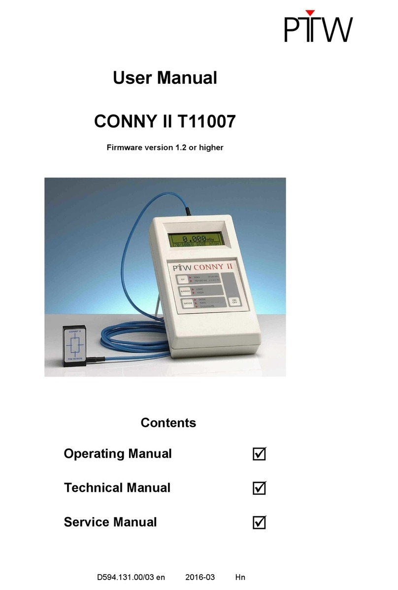
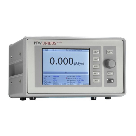
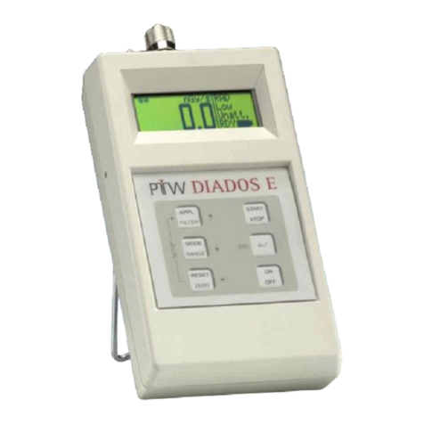
PTW DIAMENTOR E2 User manual

User Manual
DIAMENTOR E2
T11033
from SN 02000 and higher
D651.131.00/05 en 2012-11 Gü/Hn/Kau

DIAMENTOR E2
General Information
2 D651.131.00/05 en
General Information
−The product bears the CE-mark "CE-0124" in
accordance with the Council Directive
93/42/EEC about Medical Devices and fulfills
the essential requirements of Annex I of this di-
rective. The product is a class IIb device
(MDD).
−Furthermore, the DIAMENTOR E2 helps fulfill
the requirements of the EC patient directive
97/43/EURATOM regarding the acquisition and
documentation of the radiation exposure of pa-
tients during X-ray examinations.
−Product standard
The product fully complies with the require-
ments of the following standards:
IEC 60580
−Electrical safety
The product fully complies with the require-
ments of the following standards:
IEC 60601-1
ANSI/AAMI ES 60601-1 /
CAN/CSA-C22.2.No.60601-1
−Electromagnetic immunity
The product fully complies with the require-
ments of the following standards:
IEC 60601-1-2
IEC/CISPR 11 class B
−The user manual is an integral part of the prod-
uct. It should always be kept near the product.
Observance of the manual is a prerequisite for
proper product performance and correct opera-
tion.
−Operator safety, specified measuring accuracy
and interference-free operation can be guaran-
teed only if original products and parts are
used. Furthermore only the accessories listed in
this manual are approved by PTW-Freiburg and
may be used in conjunction with the product, or
else accessories whose use has been ex-
pressly permitted by PTW-Freiburg. Safe op-
eration and proper product performance are not
guaranteed if accessories or consumables from
other manufacturers are used.
−PTW-Freiburg cannot be held liable for dam-
ages resulting from the use of accessories,
consumables from other manufacturers or when
the user ignores the instructions and informa-
tion given in this manual.
−The warranty period is 1 (one) year and begins
on the day of delivery.
It is unaffected by repairs covered by the war-
ranty regulations.
−PTW-Freiburg considers itself responsible for
safety, reliability and performance of the prod-
uct only, if assembly, extension, readjustment,
modification or repair is carried out by
PTW-Freiburg or by persons authorized by
PTW-Freiburg, and if the product is used in
compliance with the technical documentation.
−In case of any questions concerning service,
support or warranty please contact your sup-
plier.
−This manual is in conformity with the product
specifications and all applicable safety stan-
dards valid at printing date. All rights are re-
served for devices, circuits, techniques, soft-
ware and names referred to in the manual.
−PTW-Freiburg reserves the right to make modi-
fications.
Please contact PTW or your local representa-
tive for the most current information concerning
the products of interest.
−No part of the technical documentation may be
reproduced without written permission from
PTW-Freiburg.
−PTW-Freiburg is registered manufacturer ac-
cording to the ElektroG (Elektro- und Elek-
tronikgeräte-Gesetz).
Elektro-Altgeräte-Register (EAR) Registration
number DE15599992.

DIAMENTOR E2
General Information
D651.131.00/05 en 3
−PTW-Freiburg works in strict accordance with a
quality management system which is continu-
ously updated according to national and inter-
national standards.
PTW-FREIBURG
Physikalisch-Technische Werkstätten
Dr. Pychlau GmbH
Lörracher Str. 7
79115 FREIBURG
GERMANY
Phone: +49 761 49055-0
Fax: +49 761 49055-70
www.ptw.de

DIAMENTOR E2
Table of Contens
4 D651.131.00/05 en
Table of Contents
1INTENDED USE 5
2FOR YOUR SAFETY 5
3OPERATING CONTROLS AND INDICATORS 11
4FIRST TIME OPERATION 12
4.1 Setting up the DIAMENTOR E2 12
4.2 Connecting the Supply Voltage 12
4.3 Connecting the Chamber and Printer and Putting into Operation 15
4.4 Mounting the ionization chamber 15
4.5 Basic Device Settings (Setup Menu) 16
5PERFORMING A MEASUREMENT 17
5.1 Constancy Check 17
5.2 Measurement 17
5.3 Air Density Correction 18
5.4 Print out 18
6ERROR MESSAGES AND TROUBLESHOOTING 19
7CALIBRATION 20
8PERIPHERALS 22
8.1 Printer 22
8.2 PC 22
9CLEANING, PREVENTIVE MAINTENANCE AND DISPOSAL 23
9.1 Cleaning 23
9.2 Preventive Maintenance 23
9.3 Disposal of the Product 24
10 TECHNICAL SPECIFICATIONS 25
11 ACCESSORIES AND SPARE PARTS 27
12 SPECIAL ADJUSTMENTS 27
13 ELECTROMAGNETIC COMPATIBILITY (EMC) ACCORDING TO IEC 60601-1-2 28
APPENDIX: CHINA ELECTRONIC INDUSTRY STANDARD COMPLIANCE 32
LITERATURE 34
INDEX 35

DIAMENTOR E2
Intended Use
D651.131.00/05 en 5
1 Intended Use
The DIAMENTOR E2 is a device for measurement
of the dose area product and the dose area product
rate in diagnostic radiology. It fulfills the require-
ments of IEC 60580.
The dose area product is measured with an ioniza-
tion chamber mounted directly to the light beam
diaphragm housing.
The DIAMENTOR E2 is a single channel micro-
processor-controlled measuring system.
The DIAMENTOR E2 is equipped with a serial con-
nector (socket SERIAL) to connect a label printer or
a PC.
This manual only describes the DIAMENTOR E2.
A detailed description of the RS232 interface is
supplied on request (document number
D651.131.1).
2 For Your Safety
The following safety statements are divided into
DANGER, WARNING, CAUTION and NOTE.
Definitions
DANGER
indicates an imminent hazard. If not avoided,
the hazard will result in death or serious injury.
WARNING
indicates a hazard. If not avoided, the hazard
could result in death or serious injury.
CAUTION
indicates a potential hazard. If not avoided, this
hazard could result in minor personal injury or
product/property damage.
NOTE
Provides useful information to assure that you
get the most from your equipment.

DIAMENTOR E2
For Your Safety
6 D651.131.00/05 en
Safety Information
DANGER
Explosion Hazard – The product is not de-
signed for use in areas of medical locations
where an explosion hazard may occur. An ex-
plosion hazard may result from the use of
flammable anesthetics, skin cleansing agents
and disinfectants. Furthermore, the product is
suitable for use in an oxygen-enriched atmos-
phere only with certain restrictions. The atmos-
phere is oxygen-enriched when the room air
contains more than 25 % oxygen or nitrous
oxide.
WARNING
Shock Hazard – Strictly observe the following
warnings. Failure to do so may endanger the
lives of the patient, the user and other persons
involved.
−The product is a system device of
IEC 60601-1 protection class II in
combination with functional earth. It may be
put into operation only when connected to a
properly installed power outlet with earthing
contact.
−The installation of the product may only be
performed by trained electro-technical staff.
−Before using the product, the user must as-
certain that it is in correct working order and
operating condition.
−Inspect the connection cables for damage
before use. Replace damaged cables and
connectors immediately.
−When disconnecting the device from the
power line, first remove the connector from
the wall outlet. Then disconnect the cable
from the device.
−Devices on which moisture condensation
has developed as a result of temperature
changes must not be switched on unless
completely dry.
−Liquids must not enter neither the display
unit nor the adapter. If liquids have entered
the product, it must be thoroughly inspected
before being used again.
−Extension cords must not be used.
Operation in the patient environment:
With all peripheral devices connected, the
product represents a medical system. The
product may be operated in the patient envi-
ronment only if
−no peripheral devices are connected to the
serial interface or
−the peripheral devices connected meet the
requirements IEC 60601-1/
ANSI/AAMI ES 60601-1 /
CAN/CSA-C22.2.No.60601-1
−the peripheral devices connected meet the
requirements IEC 60950-1 / UL 60950-1 and
are operated outside the patient environ-
ment.
Exclusion of operation as device with pa-
tient contact:
−The device is not for use in direct contact
with the patient. Neither the device nor any
peripheral device may have contact to the
patient.
−Never touch the patient and open connec-
tors of the device at the same time.
Exclusion of operation as a controlling in-
strument:
−The device is only for use to measure the
dose within radiation field. The product must
not be used to control radiodiagnostic
equipment or radiotherapy units.

DIAMENTOR E2
For Your Safety
D651.131.00/05 en 7
WARNING
Shock Hazard – Strictly observe the following
warnings. Failure to do so may endanger the
lives of the patient, the user and other persons
involved.
Use of peripheral devices:
−Peripheral devices (PC, printer) may only be
connected if they meet the requirements of
IEC 60950-1 / UL 60950-1 or of standard
IEC 60601-1 ANSI/AAMI ES 60601-1 /
CAN/CSA-C22.2.No.60601-1.
These devices may only be operated in the
patient environment, if it is guaranteed that
they meet the requirements of IEC 60601-1/
ANSI/AAMI ES 60601-1 /
CAN/CSA-C22.2.No.60601-1.
−Devices may be connected to other devices
or to parts of systems only if it has been as-
certained that this connection does not im-
pair the safety of the patient, the operator or
the environment.
−If the device specifications do not contain in-
formation as to connecting the device to
other equipment, you must consult the
manufacturer of the other equipment or an
expert about the effects of the connection on
the patient, the operator or the environment.
−Always observe standards IEC 60601-1/
ANSI/AAMI ES 60601-1 /
CAN/CSA-C22.2.No.60601-1.
WARNING
Suffocation Hazard – Dispose of the packag-
ing material, observing the applicable waste-
control regulations. Keep the packaging mate-
rial out of children's reach.
Patient Hazard – The product is a medical
electrical device and must only be handled by
persons who are trained in the use of such
equipment and are capable of applying it prop-
erly. The operator must be trained in the use of
the device.
Risk of Poisoning – Chemicals required for
application or maintenance of the device, for in-
stance, must under all circumstances be stored,
prepared, and kept at hand in their specific con-
tainers. Failure to observe this instruction may
result in severe consequences for the patient.
WARNING
Equipment failure - Electromagnetic fields are
capable of interfering with the proper perform-
ance of the device.
−The DIAMENTOR E2 should not be used in
the immediate vicinity of or placed on top of
or below other equipment. However, if the
application requires an arrangement of de-
vices as described above, the
DIAMENTOR E2 should be watched to en-
sure its proper functioning in the specific ar-
rangement.
−The customer or user of the
DIAMENTOR E2 should assure that it is
used in an electromagnetic environment as
described in IEC 60601-1-2.

DIAMENTOR E2
For Your Safety
8 D651.131.00/05 en
WARNING
Bodily Injury! Equipment Damage!
Modifications, additions or maintenance of the
equipment may be conducted only by suitably
qualified and trained persons.
Spare parts must be approved by the manufac-
turer.
After any modifications of the equipment, ap-
propriate inspections and tests have to be car-
ried out.
Failure to comply may lead to fatal or serious
personal injury and / or damage to the equip-
ment, as well as void the warranty.
WARNING
The system has no means of isolation from the
supply voltage. When the mains plug is con-
nected to the power line or the cable is clamped
into the DC supply, the system is powered,
even if the DIAMENTOR E2 is turned off.
CAUTION
Equipment damage - Handle the product with
care to avoid equipment damage.
Verify that the power ratings indicated on the
device are the same as those of your power
supply system.
Always use the product in compliance with the
user manual. Otherwise, the intended protection
can be reduced.
Use the product only in conjunction with the de-
vices approved for this purpose by PTW and/or
the devices listed in the section "Intended Use".
The ambient conditions specified in the "Tech-
nical Specifications" section must be ensured at
all times.
CAUTION
Equipment damage - If you move the X-ray
unit do not bump into doorframes or walls to
avoid damage to the DIAMENTOR E2.

DIAMENTOR E2
For Your Safety
D651.131.00/05 en 9
NOTE
Please observe the user manuals of all con-
nected system components!
NOTE
Set up the device so that the operator has a
clear, unobstructed view of the control panel.
NOTE
Do not position the device so that it is difficult to
operate the disconnecting device.
Figure 1: Definition of patient environment
Symbols on Product and Nameplate
Symbol Description
Observe the user manual.
Please refer to user manual.
The product bears the CE-mark.
The product is certified by VDE
(German Association for Electrical,
Electronic and Information Tech-
nologies)..
The product is certified by UL (Un-
derwriters Laboratories) for both
the U.S. and Canadian markets, to
the applicable U.S. and Canadian
standards.
The device is only suitable for use
with direct current.
Manufacturer and date of manu-
facture
Reference number
Serial number
Separate collection for electrical
and electronic equipment!
(refer also to section Disposal of
the Product)
Labeling according to “Administra-
tion on the Control of the Pollution
caused by Electronic Information
Products (ACPEIP)“ (China RoHS)
(refer also to Appendix)
The connection of the DIAMENTOR E2 to the
ground wire does not have any protection func-
tion here, this serves as function earth.

DIAMENTOR E2
For Your Safety
10 D651.131.00/05 en
Information for Installation
Inside the patient Outside the patient Not medical used area
environment environment
Figure 2: Note for installation in the patient environment
PTW
DIAMENTOR E2
T11033
Printer / PC
IEC 60950-1
Printer / PC
IEC 60950-1
or
Power
supply unit
T99052
Power
limiter
T26060
or

DIAMENTOR E2
Operating Controls and Indicators
D651.131.00/05 en 11
3 Operating Controls and Indicators
Figure 3: DIAMENTOR E2
1 Socket SERIAL for connection of label printer or PC (RS232 interface; RJ12 Western Plug)
2 Folding stand
3 Connection ionization chamber (connecting system A )
4 Connection adapter
5 On/Off switch Device switched on
Device switched off
6 Display (8 digit seven-segment display)
7 TEST (
→
) button to conduct a device test and for cursor control in the menu mode
8 PRINT (
↑
) button to print out the measured value on a connected printer and for cursor control in the
menu mode. If the print mode is set to ”Prn off” the print function is inactive.
9 RESET (
↵
) button to reset the reading to zero and to confirm settings and quit a menu in the menu
mode

DIAMENTOR E2
First Time Operation
12 D651.131.00/05 en
4 First Time Operation
4.1 Setting up the
DIAMENTOR E2
The DIAMENTOR E2 can be set up by means of
the folding stand on the back of the device.
Alternatively, the device can be fixed to the wall or a
plain surface by means of the velcro type ribbon
supplied with the DIAMENTOR E2. To do so, fasten
the self-adhesive back of the ribbon to the back of
the DIAMENTOR E2 and the opposite ribbon to the
wall or surface.
4.2 Connecting the Supply Volt-
age
WARNING
The DIAMENTOR E2 must only be connected
to one of the two ways described below.
Use only the listed original cable from PTW.
Observe the installation notes of the supply
voltage.
WARNING
The system has no means of isolation from the
supply voltage. When the mains plug is con-
nected to the power line or the cable is clamped
into the DC supply, the system is powered,
even if the DIAMENTOR E2 is turned off.
The DIAMENTOR E2 can be connected with two
different adapters for supply voltage (refer to fig-
ure 2).
1. Connection with PTW power supply T99052
2. Connection with power limiter T26060 to an
external supply voltage according to IEC 60601-
1/ ANSI/AAMI ES 60601-1 /
CAN/CSA-C22.2.No.60601-1
To connect the DIAMENTOR E2 follow the descrip-
tion of the used adapter.
PTW
Power Supply
T99052
Mains
PTW
DIAMENTOR E2
PTW
Chamber
(110... 230)VAC
1
PTW
DIAMENTOR E2
PTW
Chamber
2
T26060
PTW
PTW T25024-2
PTW T25024-2
24 VDC+/-10%
Double /
Reinforced
insulation
IEC 60601-1
2 MOPP
External
Supply Voltage
Figure 4: DIAMENTOR E2 connecting options

DIAMENTOR E2
First Time Operation
D651.131.00/05 en 13
4.2.1 Connection with PTW power supply
T99052
WARNING
The device is designed to meet the require-
ments of protection class II. It may be operated
only with PTW power supply T99052.
Extension cords must not be used.
The DIAMENTOR E2 is connected via external
power supply T99052 to the mains (refer to Figure
3, item 1).
CAUTION FOR USA
Installation in USA - In case of a 240 VAC-
line voltage the DIAMENTOR E2 must only be
connected to center tapped circuits.
The DIAMENTOR E2 is connected to the power
supply via supply cable T25024-2.
•Place the power supply so that mechanical
damages and penetration of liquids are
avoided. Do not place the power supply on the
ground!
Avoid injury hazard due to cable loops!
•Connect the power supply unit to the adapter
socket (refer to Figure 3, item 4). Before con-
necting the power supply unit to the power sup-
ply line, verify that the ratings of your local
power line are those indicated on the power
supply.
4.2.2 Connection with power limiter T26060 to
external supply voltage
CAUTION
Make sure that the release of the installation
manufacturer is on your hand before you con-
nect the DIAMENTOR E2 via power limiter
T26060 to the installation.
WARNING
The power source has to guarantee safety by
means of 2 MOPPs (Means Of Patient Protec-
tion) according to IEC 60601-1/
ANSI/AAMI ES 60601-1/
CAN/CSA-C22.2.No.60601-1.
The DIAMENTOR E2 may be operated only
with power limiter T26060. Extension cords
must not be used.
The connection of the power limiter T26060 re-
quires technical know-how and may only be
performed by trained electrotechnical staff ac-
cording to IEC 60601-1/ANSI/AAMI ES 60601-1
/CAN/CSA-C22.2.No.60601-1.
The DIAMENTOR E2 is connected to the power
limiter T26060 via supply cable T25024-2 and to a
low voltage supply (24 VDC) (refer to Figure 3,
item 2).
•Place the power limiter so that mechanical
damages and penetration of liquids are
avoided.
Do not place the power limiter on the ground!
Avoid injury hazard due to cable loops!
•Connect the power limiter unit via supply cable
T25024-2 to the adapter socket (refer to Figure
3, item 4). Before connecting the power limiter
to the DC supply voltage, verify that the ratings
of the DC supply voltage are those indicated on
the power limiter.

DIAMENTOR E2
First Time Operation
14 D651.131.00/05 en
Installation of the power limiter T26060 (refer to
Figure 5)
The DIAMENTOR E2 may be operated only with
power limiter T26060 in compliance with the follow-
ing conditions.
•The earth and enclosure leakage currents of the
whole installation have to be measured when
putting into operation. The earth and enclosure
leakage current may not exceed the maximum
values of 300 µA (safety class I) or 150 µA
(safety class II) depending on the safety class.
•The user replaceable mains (line) fuse must be
an approved type acceptable to the authorities
where the equipment is sold.
•The complete system has to be evaluated ac-
cording to the requirements of IEC 60601-1
ANSI/AAMI ES 60601-1/
CAN/CSA-C22.2.No.60601-1 by the end user.
•To achieve the requirements for electro-
magnetic compatibility it is recommended to
connect the DC power supply output to GND
and earth (refer to Figure 5). This earth connec-
tion has no protective function (function earth).
Maximum Earth and Enclosure Leakage Current
Measurement according to IEC 62353
Class I equipment:
The maximum leakage current is 300 µA.
Class II equipment:
The maximum leakage current is 150 µA.
Figure 5: Installation of the power limiter T26060
T26060
PTW
brown
white
24 VDC
GND
Earth Connection
2 MOPP
24 VDC ±10%
Double / Reinforced
insulation
IEC 60601-1
Power Supply
Power GND

DIAMENTOR E2
First Time Operation
D651.131.00/05 en 15
4.3 Connecting the Chamber and
Printer and Putting into Operation
•Always turn off the device before connecting or
removing peripheral devices.
•Connect the chamber to 3 (refer to Figure 3).
Use the original cables from PTW (available in
various lengths up to 40 meters (130 ft)).
•Socket SERIAL (Figure 3, item 1): Connect the
printer cable or RS232 interface cable for PC.
•Turn on the DIAMENTOR E2 with the On/Off
switch (refer to Figure 3, item 5). The firmware
version will be displayed for about 2 seconds,
followed by a display test. After completion of
the test the DIAMENTOR E2 is operational.
4.4 Mounting the ionization
chamber
General information
The DIAMENTOR E2 can be operated with every
PTW-DIAMENTOR chamber featuring connecting
system A (Figure 3, item 3).
The chamber calibration factor must be entered for
the connected chamber (section 4.5). When replac-
ing the chamber, do not forget to enter the new
chamber calibration factor (section 4.5.)
The DIAMENTOR E2 connection cables are avail-
able in various lengths (max. 40 meters (130 ft.)).
Use only the original cables from PTW.

DIAMENTOR E2
First Time Operation
16 D651.131.00/05 en
4.5 Basic Device Settings (Setup
Menu)
General information
The setup menu will be activated by pressing the
TEST and RESET buttons simultaneously for about
2 seconds In the menu mode the buttons are used
for cursor control, to change and confirm settings
and to quit a menu.
All adjustments performed in the setup menu are
saved to the non-volatile memory.
Selecting a measuring quantity
When the setup menu is called up, the current set-
tings for the measuring quantity are shown. The
settings available for the measuring quantity are
−dose area product doSE
−dose area product rate doSEr
−During irradiation display
of the detected dose area
product rate; after irradiation
display of the total dose
area product Auto
Use the TEST (→) button to toggle between the
available settings. Confirm the selected setting with
RESET (↵). After confirmation, the menu item for
setting the chamber calibration factor will be called
up automatically.
Entering the chamber calibration factor
Check the setting for the chamber calibration factor.
The original chamber factor KGis indicated on the
chamber housing.
Each time you connect another chamber, you
should enter the new chamber calibration factor as
described below.
To change the chamber calibration factor confirm
the setting for the measuring quantity with RESET
(↵). The menu item for setting the chamber calibra-
tion factor CHAF will be called up automatically.
The current setting for the chamber calibration fac-
tor will be displayed. Change the current digit with
PRINT (↑) and move to the next digit with TEST
(→).Chamber calibration factors can be set in the
range (0.01 ... 9.99).
Confirm the selected setting with RESET (↵). After
confirmation, the measuring mode will be entered
automatically. The print mode can be switched on /
off with TEST button (display Prn on / Prn off).
PC can be connected only with disabled print mode.
If the print mode is set to ”Prn off” the print function
of PRINT button is inactive. To obtain a printout of
the measured values, first activate print mode.
NOTE
Ionization chambers calibrated by PTW-
Freiburg are suitable for over couch tubes and
under couch tubes. To compensate for the cali-
bration error inherent in the system, the cham-
ber calibration factor may be multiplied by a cor-
rection factor. The correction factor for over
couch tubes is 1.10, for under couch tubes,
0.95 (refer to section 7).
We recommend to have the system calibrated
annually or every 2 years by specially trained
staff on site or in our calibration laboratory of
PTW-Freiburg.

DIAMENTOR E2
Performing a Measurement
D651.131.00/05 en 17
5 Performing a Measurement
5.1 Constancy Check
CAUTION
Faulty measurement - Check the device per-
formance every day, before putting the
DIAMENTOR E2 into operation.
Before using the DIAMENTOR E2, check that
its measurement range matches the examina-
tion technique that will be applied.
Reset the DIAMENTOR E2 before each exami-
nation.
The DIAMENTOR E2 will conduct an internal con-
stancy check as soon as the TEST button is
pressed for 2 seconds. The return value of the
hardware test is the proportional relation between
measured value and an internal test value. After
about 5 seconds the DIAMENTOR E2 returns auto-
matically to the measuring mode.
If the proportional relation between measured value
and test value is not within the range of 95 ... 105
the device needs to be calibrated before it can be
used again.
5.2 Measurement
NOTE
Allow for a pause of at least 10 seconds be-
tween the activation of the device and the first
measurement (section 10).
Press the RESET button before starting the first
measurement to bring the DIAMENTOR E2 into
a defined initial state.
After the device has been turned on, the firmware
version has been displayed for about 2 seconds
and the display test has been completed success-
fully measured values are displayed according to
the selected mode as soon as radiation is detected.
„Auto“ measuring mode (Setup: Auto)
During irradiation display of the detected dose area
product rate in µGym²/s; after irradiation display of
the total dose area product in µGym².
„Dose rate“ measuring mode (Setup: doSEr)
Display of the dose area rate in µGym²/s. This
mode is indicated by a square at the left margin of
the display.
„Dose“ measuring mode (Setup: doSE)
Display of the total dose area product in µGym². In
this mode the display will be refreshed every sec-
ond.
CAUTION
Faulty measurement - Accessories placed be-
tween the chamber and the patient, such as a
pediatric filter or beam applicator, will reduce
the dose area product relevant for the patient.
In this situation the DIAMENTOR E2 will display
measuring values that are too high. According
to national regulations in Germany, however, it
is sufficient to record the measuring value and
the accessories in use for reconstruction of the
radiation exposure level. If these accessories
are used for all measurements, the
DIAMENTOR E2 should be recalibrated with
the accessories installed.
Equipment damage - The DIAMENTOR E2
should be operated only when an ionization
chamber is connected or when the chamber
connection at the device is covered.

DIAMENTOR E2
Performing a Measurement
18 D651.131.00/05 en
5.3 Air Density Correction
To get the highest possible measuring accuracy the
indicated / determined value of the
DIAMENTOR E2 must be multiplied with a correc-
tion factor to the air density correction.
The air density correction factor is calculated by the
following formula:
0
0
Tp
Tp
KD•
•
=
p0= 1 013 hPa
p = current air pressure
T0= 293 K (= 20°C)
T = current temperature
According to device, the correction can perhaps be
executed over a correction menu or an used soft-
ware.
5.4 Print out
The print mode can be switched on / off (display
Prn on / Prn off) over setup menu (refer to sec-
tion 4.5).
•Set print mode to “Prn on”
•Connect the printer to the DIAMENTOR E2
(refer to Figure 3, item 1).
•Press the PRINT button to obtain a printout of
the measured value.
•To start a new measurement press the RESET
button to reset the display to zero.

DIAMENTOR E2
Error Messages and Troubleshooting
D651.131.00/05 en 19
6 Error Messages and Troubleshooting
Message Cause Remedy
OFL-Err (Overflow
Error)
The dose area product has exceeded
20 000 000 µGym²
or
the dose area product rate has exceeded
15 000 µGym²/s
Press the RESET button.
Error 51 communication error Turn the device off and on again. When
the message appears again the device
must be repaired.
Error 54 Memory malfunction Turn the device off and on again. When
the message appears again the device
must be repaired.
HU-Err Chamber voltage missing, device is un-
able to measure
Disconnect the chamber cable from the
DIAMENTOR E2. When the message
continues appearing the device is defec-
tive and must be repaired.
When the message clears the chamber
cable is defective and must be replaced.

DIAMENTOR E2
Calibration
20 D651.131.00/05 en
7 Calibration
Electrical Calibration
The DIAMENTOR E2 is electrically calibrated in the
factory. You can verify the calibration as described
in section 5.2. If the electrical calibration values are
outside the admissible range, the device should be
returned to PTW-Freiburg for repair, as the electri-
cal calibration cannot be corrected on site.
Radiological Calibration
The chamber calibration can be verified on site (see
below) or in the PTW calibration laboratory. We
recommend to have the system calibrated annually
or every 2 years in our calibration laboratory of
PTW-Freiburg.
Some Basic Facts On Chamber Calibration
(PTW-Freiburg Calibration Laboratory)
−For verification of the chamber calibration fac-
tor only the ionization chamber (without the
measuring system) needs to be returned to the
factory.
−The ionization chambers calibrated in the PTW
calibration laboratories can be used with over-
couch and undercouch tubes.
−In order to take into account the different ab-
sorption conditions of overcouch and under-
couch tubes, an additional absorber equivalent
to 0.35 mm AI is placed between the X-ray
tube and the ionization chamber during the
factory calibration. Therefore the measure-
ment error of overcouch tube installations
where there is no absorber between chamber
and patient is up to - 9 %. In conjunction with
undercouch tubes the absorption of the patient
couch situated between the patient and the
chamber is equivalent to 0.5 to 0.7 mm AI,
which results in a measurement error of up to
+ 5 %.
−The chamber calibration factors are noted
down on the calibration certificate.
−Enter the new chamber calibration factors as
described in section
4.5. For this, multiply the
chamber calibration factor KGby a correction
factor of 1.10 for over-couch tubes and of
0.95 for under-couch tubes.
Verifying the Chamber Calibration in Conjunc-
tion with the X-Ray System
Specially trained staff will be able to perform the
chamber calibration on site. The required accesso-
ries/tools are:
−1 diagnostic dosemeter (e.g., PTW-DIADOS,
PTW-DALi, PTW-NOMEX or PTW-UNIDOS)
−1 X-ray film, 13 cm x 18 cm (for radiography)
−1 measurement phantom (for fluoroscopy)
−1 adapter for DIADOS detector (part no.
T20002), (for fluoroscopy)
Check the electrical calibration as described in sec-
tion 5.1.
Radiography
−Make adjustments for a field size of approx.
10 cm x 10 cm and mark the area on the pa-
tient couch.
−Place the X-ray film on the patient couch and
make a radiograph (70 kV and 40 mAs).
−Develop the film (only briefly to obtain sharp
edges) and measure the exact size of the field
(noting down the result A).
−Place the detector of the diagnostic dosemeter
in the center of the area marked on the patient
couch. Make a radiograph (70 kV and 40 mAs).
Table of contents
Other PTW Measuring Instrument manuals
Popular Measuring Instrument manuals by other brands
Littelfuse Startco
Littelfuse Startco SE-601 manual
Trotec
Trotec BP21WP operating manual

Kikusui
Kikusui AVM13 instruction manual
Newport
Newport CONEX-LDS Command Interface Manual
Endress+Hauser
Endress+Hauser Levelflex M FMP43 operating instructions
Electro-Tech systems
Electro-Tech systems ASTM D 991 TEST FIXTURE operating manual
Flow vision
Flow vision FS10-dbEX Instructions for installation
ATAGO
ATAGO PAL-84S instruction manual
DUALPULSE
DUALPULSE DP490 instruction manual
Advanced Energy Industries
Advanced Energy Industries LumaSense Technologies E2T Quasar 2 Series quick start guide
Sylvac
Sylvac S Mike PRO Smart instructions
Niigata seiki
Niigata seiki GDCS-150DCD instruction manual


