Start italiana XMT User manual

INSTALLATION
MANUAL
XMT
MAGNETOSTRICTIVE
LEVEL PROBE
XMT rev.03 2015-04 - ENG
2
INDEX
INDEX...........................................................................................................................................................................................................................................2
REVISION INDEX........................................................................................................................................................................................................................2
INTRODUCTION ........................................................................................................................................................................................................................3
GENERAL WARNINGS ..............................................................................................................................................................................................................3
DESCRIPTION.............................................................................................................................................................................................................................4
MAIN COMPONENTS ..............................................................................................................................................................................................................5
MECHANICAL INSTALLATION ...............................................................................................................................................................................................6
INSTALLATION PROCEDURE..................................................................................................................................................................................................6
ELECTRICAL CONNECTION....................................................................................................................................................................................................8
EXTERNAL INSTALLATION SCHEME.....................................................................................................................................................................................9
RS485 BUS CONNECTION: ................................................................................................................................................................................................... 10
MARKING AND SERIAL NUMBER ......................................................................................................................................................................................... 11
ELECTRONIC BOARD ............................................................................................................................................................................................................. 12
ATEX CERTIFICATE AND CESI NOTIFICATION ................................................................................................................................................................. 13
REVISION INDEX
DATE
REVISION NUMBER
DESCRIPTION
0
INITIAL RELEASE
09/2011
1
General revision
09/2014
2
General amendments and layout revision
04/2015
3
Notification
This product complies with EU Directive 2012/19/UE.
The crossed-bin symbol fixed on the device indicates that the product, at the end of its useful life, should be
disposed of separately from household waste, must be taken to a collection point for electrical and electronic
equipment.
Nota: Start italiana Srl, in respect of its quality duty may modify its production and data shown into this manual. This
manual cannot be copied, neither partially, without authorization.

XMT rev.03 2015-04 - ENG
3
INTRODUCTION
This manual gives all the installation and use instructions for XMT level probes.
GENERAL WARNINGS
Before the installation and use of the equipment please carefully read the instructions given into this manual.
The manufacturer is not responsible of any possible operation not mentioned into this manual.
Any failure or faulty operation would occur to the equipment, please refer to the authorized personnel for maintenance
or directly to the manufacturer only.
The manufacturer refuses all responsibility for any eventual injury and/or damage to things caused to the non-
observance of the safety regulations.
The assigned personnel is required to know all the safety regulations relative to the hereby described equipment.
Any doubt may occur about the equipment running please refer to the authorized personnel for maintenance or
directly to the manufacturer.
Tampering releases the manufacturer from any responsibility in front of the competent authority.
This product is used in fuel tanks and in hazardous areas for risk of explosion and fire. Subterranean leakages of the fuel
tanks may cause serious damages to environment and injury.
XMT rev.03 2015-04 - ENG
4
DESCRIPTION
The magnetostrictive level transmitters are based on the principle named Wiedemann effect and enable continuous
and highly accurate reading of liquids’ level.
The XMT level transmitter consists of a microprocessor based electronic circuit placed inside one aluminum case
head and a stainless steel shaft containing a wave guide placed inside the tank.
An high frequency electric impulse is transmitted through the electronic device. At the matching point with the
magnetic field generated by the permanent magnet placed inside the float, a mechanical impulse is generated thanks to
the magnetostrictive torsional strain. The mechanical impulse spreads through the wave guide to the speed of sound up to
the sensor in the measuring head. The timing between the transmission of the going impulse and the return impulse define
exactly the position of the floats.
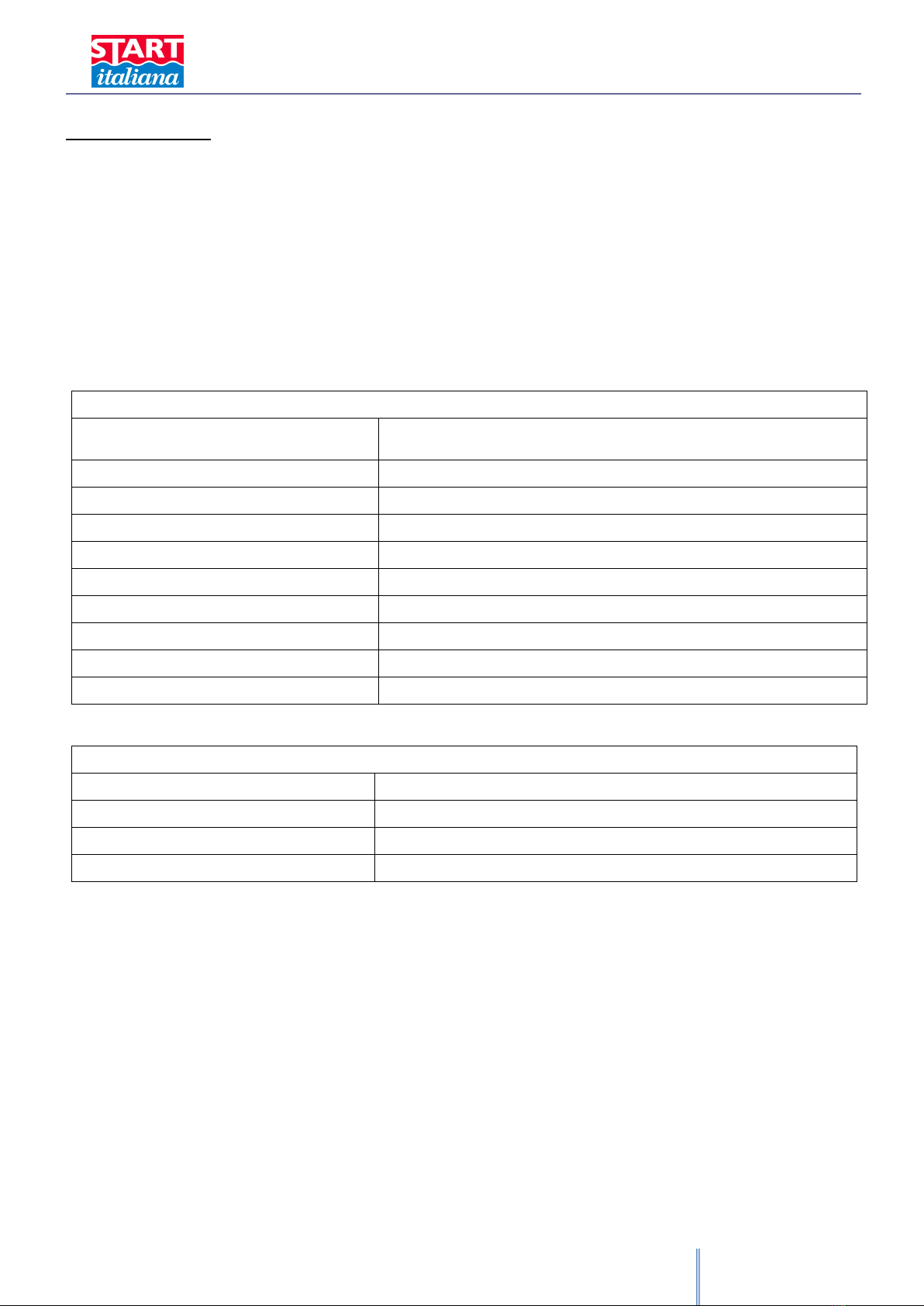
Main features
Measurable product
Diesel, fuel, propane (GPL), water
According to the float
Accuracy
± 0,5 mm probe with serial output
Resolution
0,1 mm
Repeatability
± 0,1 mm probe with serial output
Supply
9-30Vcc
Absorpion
< 50 mA
Temperature accuracy
± 0,5°C
Temperature measuring range
-45°C ÷ +130°C
Ambience temperature
-20°C ÷ +60°C
INERIS Exd execution
II 1/2 GD Ex d IIA T6 Ex tD A21 IP66/68
Technical features
Body
Ø 110 mm
Float
Ø 50 mm (other dimensions on demand)
Shaft
Ø 16 mm
Measurable height
500 ÷ 6000 mm
XMT rev.03 2015-04 - ENG
5
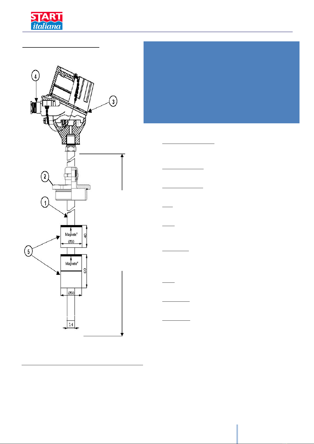
MAIN COMPONENTS
1 Stainless steel shaft AISI 304 - Length from 200 to 6.000 mm
2 Sliding nipple 2” F gas nickel plated brass
3 Die-casted aluminium case IP68
4 Cable gland EExd ½”NPT IP68
5 Floats
Shaft length L . mm……….
Tank standard connection:
Adjustable threaded 3/4”NPT-2”M Gas
Special ones on demand
Electrical connection:
Cable gland EExd ½”NPT IP68
Guide shaft AISI 304:
Diam. 16X2
Case:
Explosion proof IP68 in painted aluminum
Floats:
Foam PVC with closed cells and no-sticking flaps Diam. 50mm
Other materials and dimensions on demand
Temperature:
Liquid: -45°C + 130°C
Head: -25°C + 85°C
ATEX version: -25°C + 60°C
Cable:
Double shielding, twisted, hydrocarbur resistant, 10mm sheath
Power supply:
External supply 9-30 Vdc
Power output:
- RS 485 serial output
- Conversion board from RS485 protocol to 4-20 mA is
available (4 wires technology). In this case only the product
level will be converted into 4-20mA.

XMT rev.03 2015-04 - ENG
6
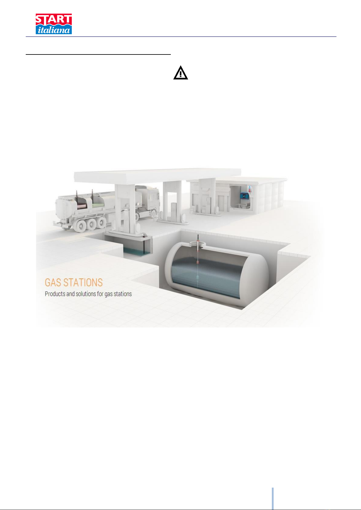
MECHANICAL INSTALLATION
If mixed with air, the flammable vapors may cause explosion. Hazardous areas may be originated therefore by the
presence of gas or vapors.
Explosions or fire may cause damages, even lethal.
The magnetostrictive probe can be installed in hazardous areas.
INSTALLATION PROCEDURE
The XMT magnetostrictive level probe is supplied into carton package of one or two pieces. We recommend to check
packing integrity.
1. When removing from original packing please pay attention not to bend the stainless steel men-hole reminding that
it is an electronic device.
2. The standard version of level probe XMT is supplied with a sliding 2” gas M fitting and the assembled floats enable
to easily shift into 2” connection. This makes the probe insertion inside the tank easier,this means that no part of
the probe must be disassembled for tank insertion operation.
3. The probe must be placed as much as possible in the center of the tank, it must be far from the product loading.
4. The probe must be assembled by keeping the body as high as possible in order to avoid its flooding.
5. It is recommended to use a 2” riser outside the tank to protect it mechanically.
6. Before introducing the probe inside the tank please check the correct floats positioning and clamping of the shaft
end.
7. Carefully unpack the level probe and insert it inside the tank.
8. Insert the probe in the 2” G-F tank gate and make it reach the floor with care then raise it of at least 10mm, this
will avoid bending of the shaft in case loading operation make tank deforming.
9. The level probe must be placed in vertical position inside the tank. The shaft inside the tank must not be either
folded or blended and must not be subjected to impact or stress.
10. Tighten the adjustable fitting until full clamping on the shaft. Connect probe cable to the plant as described
afterwards.
11. Connect sensors as described into “Electrical connection “section.

XMT rev.03 2015-04 - ENG
7
IMPORTANT: if the probe is installed without leaving at least 10mm space from the bottom of the tank and blocked on the
top with a sliding connection, any deformation of the tank that occurs will bend the probe compromising the correct
functionality.
Riser 2” as reinforce for the shaft
external off the tank. Keep the sliding
connection as near as possible to the
head.
At least 10 mm from the bottom

XMT rev.03 2015-04 - ENG
8
ELECTRICAL CONNECTION
In case of hydrocarbour vapor use anti-sparks tools
The installation must be realized by specialized people
Respect the safety rules
Read carefully the instruction given into this manual
The manufacturer is not responsible for any damage and/or supplementary costs due to the missing respect of the
supplied instructions.
The probe is supplied with 2 m of cable (1) connected through an ex-proof cable gland (2) to the probe head.
This cable must be connected to the back bone using an ex-proof junction box and an ex-proof cable gland.
It is recommended not to cut the cable for an easy extraction of the probe from the tank in case of maintenance.
It is recommended the usage of junction box JB IP68 Exd supplied by Start Italiana under request.
WARNING: the supplied 3 mt cable is moulded inside the probe head with special compound to improve the water proof;
its removal compromises the probe functioning, and affect the guarantee and the ATEX certification.
Insert the cable into the console in the locking joint (4).
The cable inside the locking joint must be without external rubber isolation.
Perform the electrical connections into the junction box as shown by the electrical scheme below.
After having tested the good functioning of the system, the locking joint must be filled with resin to avoid the
eventual hydrocarbon vapor infiltrations.
Note A
Installation made in compliance with CEI 64-8 and CEI EN 60079-14 standards.
Note B
Use cable compliant with regulation in force in the country of installation.
64-8 Electrical installations with nominal voltage not higher than 1000 Vac and 1500 Vdc. 60079-14 (1998) Classif.CEI 31-33 “Electrical costructions for
explosive area for gas presence” Part 14: Electricla installation in ex-proof area for gas presence (excluded mines).
XMT rev.03 2015-04 - ENG
9
EXTERNAL INSTALLATION SCHEME
The installation must be realized by specialized people
Respect the safety rules
Read carefully the instruction given into this manual
The manufacturer is not responsible for any damage and/or supplementary costs due to the missing respect of the
supplied instructions.
Note A
Installation made in compliance with CEI 64-8 and CEI EN 60079-14 standards.
Note B
Use cable compliant with regulation in force in the country of installation.
64-8 Electrical installations with nominal voltage not higher than 1000 Vac and 1500 Vdc.
60079-14 (1998) Classification CEI 31-33 “Electrical constructions for explosive area for gas presence”
Part 14: Electric installation in ex-proof area for gas presence (excluded mines).
XMT rev.03 2015-04 - ENG
10
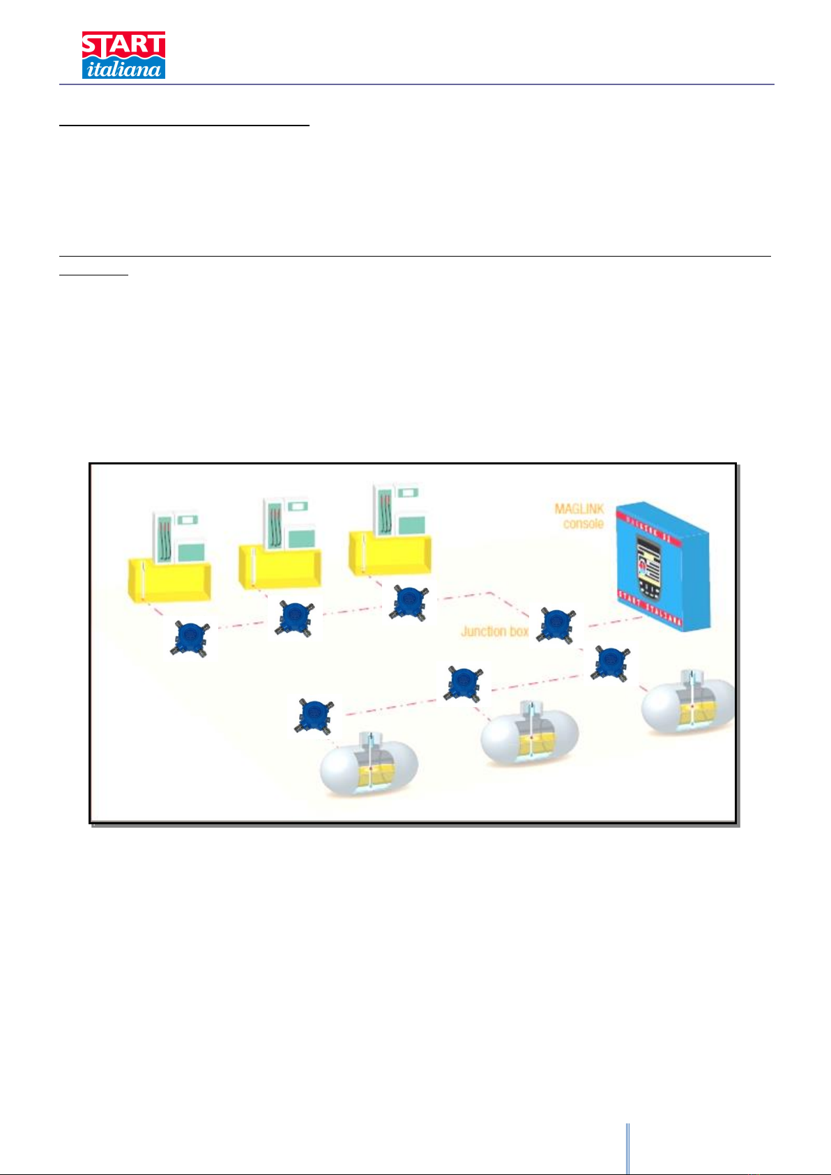
RS485 BUS CONNECTION:
Standard connection scheme of the probes to the bus RS485. Every probe is connected in parallel. If possible please
use Start Italiana’s IP68 shunt boxes already equipped with connecting terminal.
The 4 wires cable has always red-brown-blue-white colors.
Connect to the terminal the same color type: red-red, white-white, etc.
Shielded cables have all to be connected in parallel as a fifth wire and connected to the earth into the office using a protected
ground tap.
Any possible double wall and sump sensors will need the same connection on the same bus.
For connection and programming of the consoles please refer to the manual provided together with the device.
XMT rev.03 2015-04 - ENG
11
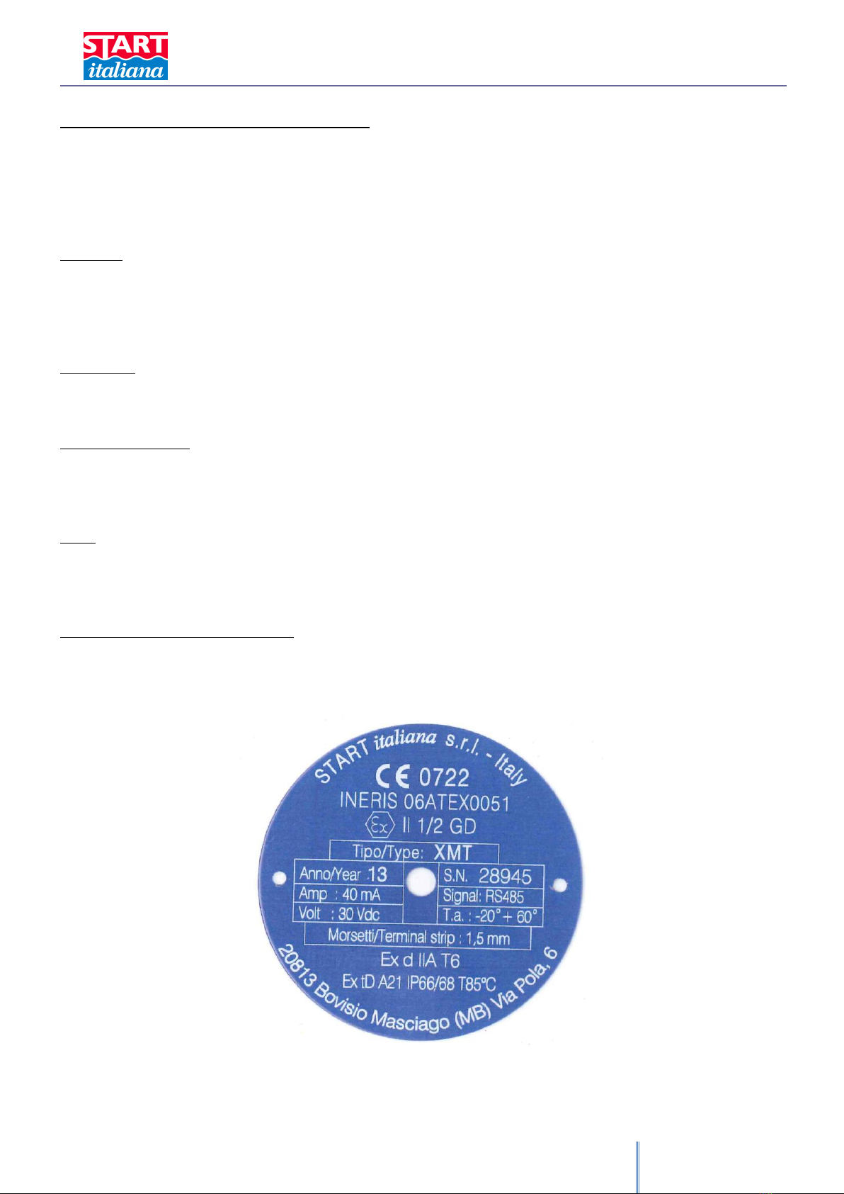
MARKING AND SERIAL NUMBER
Every probe has a unique identification serial number (S.N.) which is also the ID Address of the probe.
Take note of the S.N. (ID address), it will be required during system recognizement through the set-up Software.
On the cap head there is a metallic label with laser marking which is showing the following information:
MARKING:
Manufacturer: START ITALIANA SRL –20813 Bovisio Masciago (MB) - Italy
Type: XMT-XCR-XLR-DGM
CE e O.N.: 0722
Group: II ½ GD
EXECUTION:
EEx d IIC T6 IP66/68 T 85° for level probes with /titanium/hastelloy float
EEx d IIA T6 IP66/68 T 85° for level probes with PVC float
LABORATORY: INERIS
A nom: …
N° certificate: …..
V max: …
Signal
S.N. and probe address
T.a.: -20° +60°
Year of manufacture:
FUSION MARKING ON THE CAP HEAD:
Keep cover tight when circuits alive

XMT rev.03 2015-04 - ENG
12
ELECTRONIC BOARD
Pos
Component
1
Power supply 12-30V 2,1
RED
2
RX
BROWN
3
TX
BLUE
4
0 V
WHITE
Probe 1
Probe 2
Max no. of probes: 32
Brown
Blue
White
Red
4 = White
3 = Blue
2 = Brown
1 = Red
4 = White
3 = Blue
2 = Brown
1 = Red
XMT rev.03 2015-04 - ENG
13
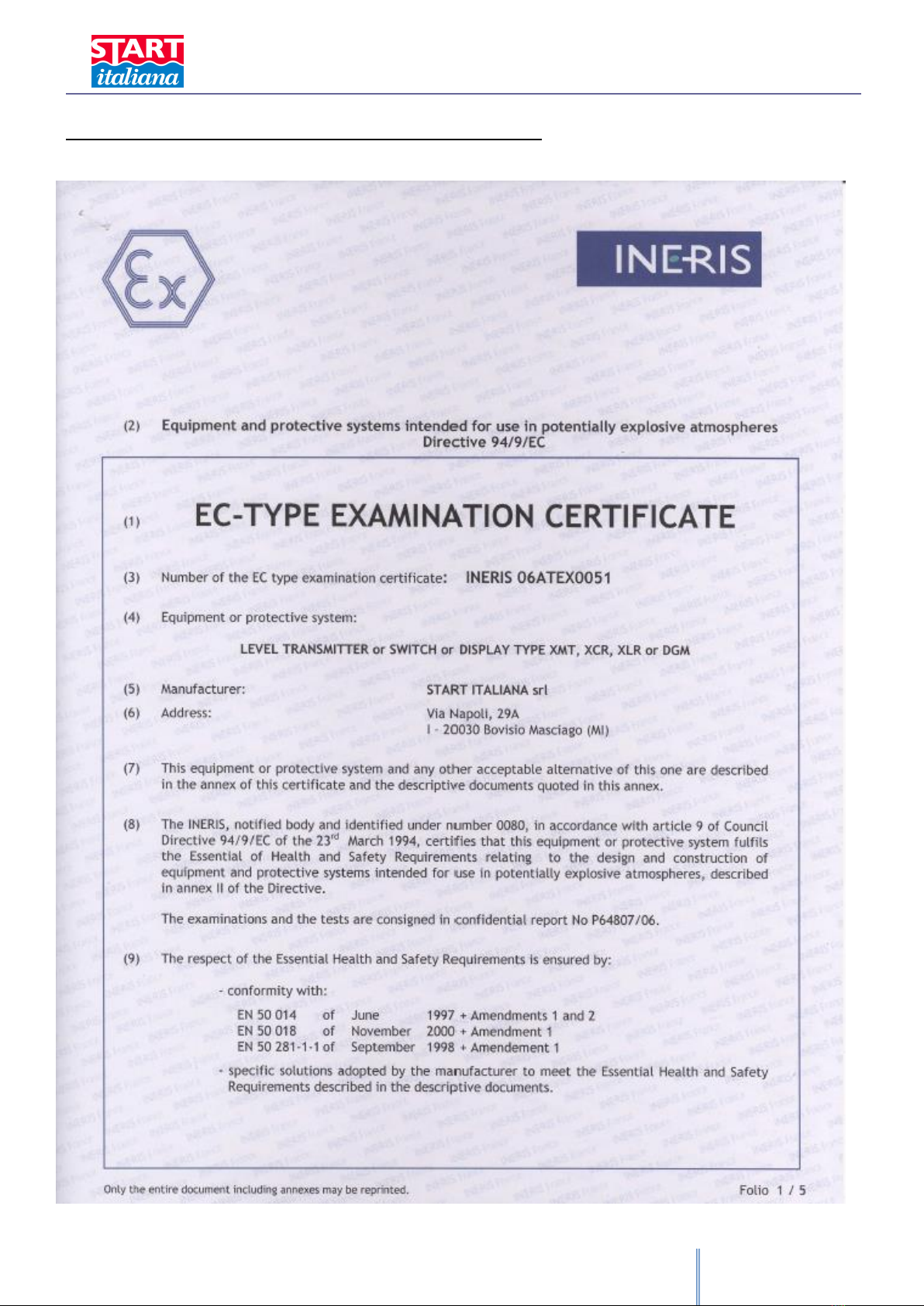
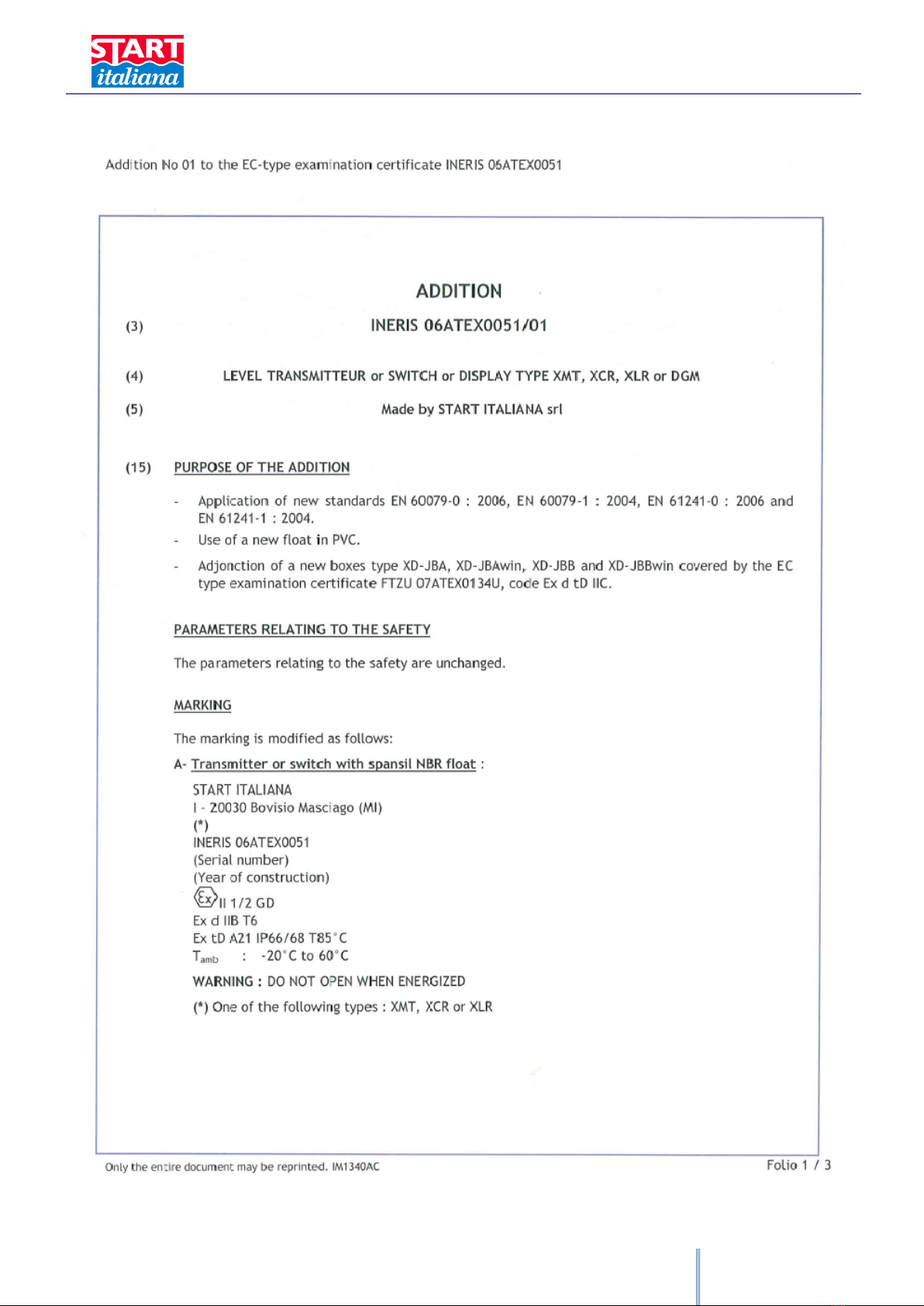
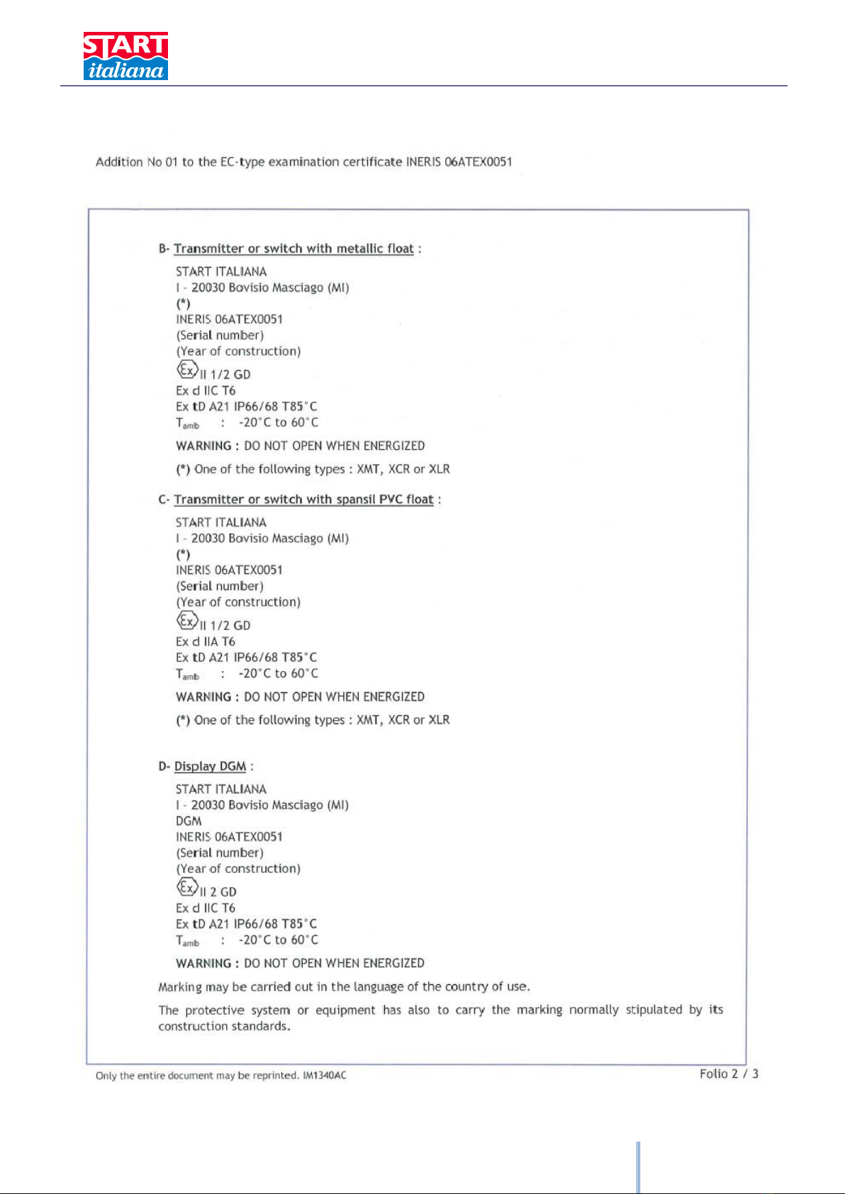
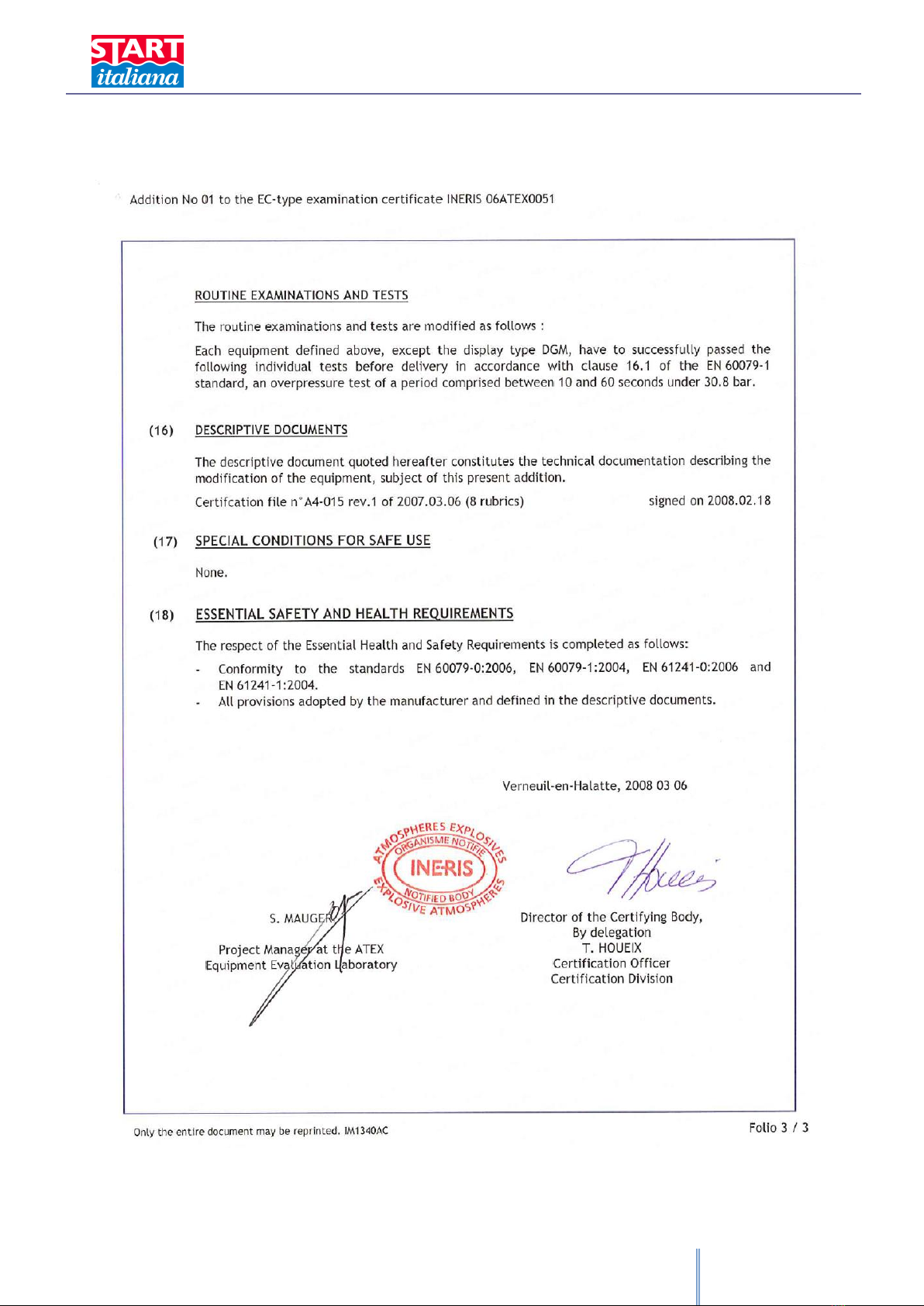
ATEX CERTIFICATE AND CESI NOTIFICATION

XMT rev.03 2015-04 - ENG
14

XMT rev.03 2015-04 - ENG
15

XMT rev.03 2015-04 - ENG
16

XMT rev.03 2015-04 - ENG
17
XMT rev.03 2015-04 - ENG
18
XMT rev.03 2015-04 - ENG
19
XMT rev.03 2015-04 - ENG
20
Table of contents
Other Start italiana Measuring Instrument manuals


