Starway LASERTECH 5000 User manual

www.star-way.com User Manual
LASERTECH 5000 1
LASERTECH 5000

www.star-way.com User Manual
LASERTECH 5000 2
Content
1. Projector Introduction 3
2. Installation Instruction 4
3. Operation Instruction 11
4. Safety Identification 15
5. Accessories 17
Notices:
1、 Due attention should be paid to this user instruction before applying this projector.
2、 Professional installer and a licensed Electrician install projector.
3、 Keep it dry and put it in the well-ventilated place, vibration and bump avoid.
4、 Avoid direct exposure!
5、 Ambient temperature: 10~35°

www.star-way.com User Manual
LASERTECH 5000 3
Projector Introduction
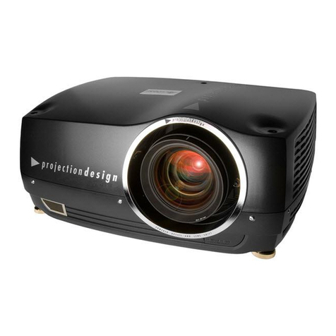
The LASERTECH 5000 is designed convenient for customers with control system
in one housing and lasers in another, different output laser housing changeable to
meet unique requirement. It is the combo to be able to play animation, DG effect,
beam effect and at same time boasts linear adjustable DPSS lasers, easier to
operate Pangolin build in control system, Cyperlite control software, high speed
USB connector, ILDA DB 25, larger memory. All of the above features are enough
to guarantee you pleasure laser show feast.
◆ Mode:DMX mode、Projector is capable to be controlled by computerized
soft through USB and by ILDA signal.
◆ DMX Channel:4、8、12、24 Channels selectable
◆ Show:More than 400 show (editable)
◆ Laser:R > 1600mw 635nm 、G > 2500mw 532nm、B > 1000mw 473nm
◆ Scan System:ILDA24K
◆ Control System:Pangolin built in system
◆ Beam Effect: 6 Beam Turret Positions, 10 Total Targeting Beams, 20
Position Rotating/ Selectable DG, Dual counter Rotating DG effect,
180°Static Linear DG Effect, 180*180 Static Grid DG effect
◆ Memory:128MB
◆ Input Voltage:AC 110V~240V 60/50Hz
◆ Power:240W
◆ Dimension:1393×426×(365~395)mm
◆ Weight:***Kg

www.star-way.com User Manual
LASERTECH 5000 4
Remove panel
Installation Instruction
Installation
Please assemble laser and control housing together as follows:
1. Place two parts on the platform and adjust them to the same height.
1、Remove the panel as illustrated:
2、Keep smooth connection of power and DB9 connector between two parts of
the projector. Then screw them tightly.

www.star-way.com User Manual
LASERTECH 5000 5
3、Insert laser housing to control housing and then fix joint with screws.
Joint two parts
to
g
ethe
r
Drive 8 screws in joint

www.star-way.com User Manual
LASERTECH 5000 6
1 2 3 4 5 6 7 8 9 10 11
Control Panel
1、PowerSwitch 2、AC Power(W/FUSE)
3、KeySwitch 4、DMX Through (linking)
5、ILDADB25 6、DMX Input
7、Emergency 8、Memory Card Slot
9、miniUSBConnector 10、Status Indicator
11、DMX Dipswitch
a—XGain b—YGain
c—RedIntensity d—GreenIntensity
e—Blue Intensity
Connectors
◇ DMX connector: used for DMX and linking mode. Only one of the effective
consoler and master respectively are required in one chain, otherwise
signal will be disturbed thus problems are resulted in projector.
a
C
b
d
e

www.star-way.com User Manual
LASERTECH 5000 7
1 2 3 4 5 6 7 8 9
◇ ILDA DB25 connector: User will find an easier way to input ILDA signal form
here which supports “plug n in” function, which will be given the priority
rather than DMX signal. However, it is advised never to pull out of the
connector during projector running.
◇ Key switch: laser power is controlled by this switch. When it is turned to
horizontal position (the key could not be removed), this unit emits laser in
15 seconds; in vertical position, unit stops emitting laser. For safety
purpose, when not in use, please remove the key from this unit.
◇ DB9 connector: DB9 connects witch Estop through pin 5 and 9 the voltage
between which is 24V. User holds choices where to set the Estop with 18#
cable, typically 150 meters.
Laser Aperture
1、Scannedbeamaperture 2、Beam Turret Positions
3、BeamTurretPositions 4、Beam Turret Positions
5、DualcounterrotatingDG 6、20 Position Rotating DG
7、BeamTurretPositions 8、Beam Turret Positions
9、Beam Turret Positions

www.star-way.com User Manual
LASERTECH 5000 8
Beam Path Alignment
If laser beam distracts from the original way during transportation, please follow
the instruction below to align beam path.
1、Pull out of the plastic cap from the projector illustrated above.
2、Insert M4 spanner included into hole
3、Turn the spanner slowly to check the angle of inside gimbal
4、Align screws in two holes till expected path you find
5、Take out off spanner and cap two holes.
Insert hex spanner into the hole
to align gimbal to change laser
beam path

www.star-way.com User Manual
LASERTECH 5000 9
1 2 3 4 5 6 7 8 9 10
Four legs are adjustable
Target Beam setting
This projector is designed with flexible target beam setting means. One is to align
inside gimbalintroduced above;Now we will introduce another mean.
1、Adjustable legs
2、How to Set Target Beam
1、4、7、10 Screw to adjust gimbal mount
3、6、9 Screw to fix gimbal
2、5、8 Screw to micro adjust gimbal

www.star-way.com User Manual
LASERTECH 5000 10
Operation Instruction
AC Power the Projector
The projector input voltage is AC110~240V 60/50Hz must be well grounded
to ensure stable power. Remove the fuse holder and insert the fuse with AC 220V
50Hz 5A in the fuse holder, then insert the fuse holder in the empty slot in the
mains input socket. The order to power the projector is the turn the main power on
and then laser. To plug or remove connectors during operation of the laser
projector may cause problems to laser projector. Therefore it is advised to ensure
all connectors are well plunged prior to operation.
DMX Mode
This projector is ready to be controlled in DMX mode through DMX address
settings. Alternatively as per unique demand, 4, 8, 12, 24 channels are selectable
at one time to realize certain customized functions.

www.star-way.com User Manual
LASERTECH 5000 11
Flashback 3 SE with extended BT - FW 6.20
CHANNEL 1 0-31 33-95 97-159 161-223 225-255
A
CCESS BLACKOUT BASIC RANGE STANDARD RANGE EXTENDED RANGE FULL RANGE
CHANNEL 2 0-15 17-31 33-47 49-63 65-79 81-95 97-111 113-127 129-143 145-255
PAGE 123 4 5 6 7 8 9 9 continued...
(
ALL 9 PAGES IN SOUND TRIG
CHANNEL 3
CUE 0-31
BLACKOUT 1 2 3 CUE1 = 33-35, CUE2 = 37-39,..., CUE48 = 221-223
7 8 9 10 ... ... 48 225-255
SOUND TRIG
CHANNEL 4 0-15 17-31 33 ... ... 64 ... ... 128 ... ... 255
SPEED
CHANNEL 5
FADE
CHANNEL 6
100% PAUSE
Black ...
25% ... ... 50% ... ... 100% ...
0-255
0-255
... 200%
... Full bri
g
htness
ZOOM
CHANNEL 7
Zero size ... ... Full size
0-255
X SIZE
CHANNEL 8
Y SIZE
CHANNEL 9
Negative full size ... Zero size
0-255
Negative full size ... Zero size
0-255
... Positive full size
... Positive full size
Z ANGLE
CHANNEL 10
X POSITION
CHANNEL 11
0 degrees ... ... 360 degrees
0-255
Left ... Center ... Right
0-255
Y POSITION
CHANNEL 12
V
ISIBLE POINTS
Down...
No visible
Cente
r
0-255
... Up
... All
p
oints visible
CHANNEL 13 0-31 33 ... ... 64 ... ... 128 ... ... 255
SCAN RATE DEFAULT 25% ... ... 50% ... ... 100% ... ... 200%
CHANNEL 14 0-31 33 ... ... 255
RELEASE TIME
CHANNEL 15
NONE
0-31
0.1
33-223
... 4 sec
225-255
COLOR
CHANNEL 16
FX-1
CHANNEL 17
FX-2
CHANNEL 18
DEFAULT RED - ORANGE - YELLOW - LIME - GREEN - CYAN - BLUE - PURPLE - PINK - REDWHITE
0-31 33-255
OFF ON
0-31 33-255
OFF ON
0
-
31
33
-
255
FX-3 OFF ON
CHANNEL 19
FX-4 0-31 33-255
OFF ON
CHANNEL 20 0-31 G1 = 33-39, G2 = 41-47,..., G20 = 185-191 193-207 209-223 225-239 241-255
FX-5
(
Holo 20
)
OFF 1 2 3 4 5 6 7 8 9 10 11 12 13 14 15 16 17 18 19 20 WALK JOG RUN WARP
CHANNEL 21
FX-6 (Mach 1)
CHANNEL 22
0-31
OFF
0-31
33 ...
FULL SPEED CCW ...
33 ...
137-151
STILL
137-151
... 255
... FULL SPEED CW
... 255
FX-6
(
Mach 2
)
OFF FULL SPEED CCW ... STILL ... FULL SPEED C
W
CHANNEL 23
FX-7
CHANNEL 24
FX-8
0-31 33-255
OFF ON
0-31 33-255
OFF ON


www.star-way.com User Manual
LASERTECH 5000 13
Cypher Lite Software Control
The projector is also capable to be control by the Cypher lite Software include in CD
only if it is connected by above USB2.0 connector with computer, who will
recognize the related hardware in the laser projector automatically. However, if it is
the first time to use Cypher lite software to control this projector, it is required to
intall “USB drive” in then same CD first as steps showed below.
Click “next”, the following window will jump to the screen.

www.star-way.com User Manual
LASERTECH 5000 14
Click “Browse” and select “USB_Driver” folder in new window, then press“OK” to
return last step and by clicking “next” to finish the installation of “USB Drive”.
Please copy the whole folder in CD to hard drive of your computer. Open
CYPHERLT.EXE the executive file offering you simply way to edit and play
DG effect, beam effect and other lase shows. As for detail how to use this file,
please refer to “help file” inside this software.
It will guarantee you smooth laser animation perfermance if it is downloaded in the
memory card
ILDA Signal Control
Once this laser projector receives effective ILDA signal, it will give priority to be
controlled under such signal even in the mode.

www.star-way.com User Manual
LASERTECH 5000 15
Warning: Avoid exposure to beam: avoid
direct eye contact with laser light. Never
intentionally expose your eyes or others to
direct laser radiation.
This laser product is a ClassIV laser and
has an interlocked housing. Avoid direct
exposure to beam
There are no user serviceable parts
inside. Tampering or removing
warranty seals will void your products
limited warranty.
A Combo label with the Product Model
Number, Serial Number, Date of
Manufacture, Laser Light Warning Label,
Warranty Void Label and Interlocked
Housing Label
Safety Identification
Warning Identification
Class Identification
Warranty Void Information
Product Information

www.star-way.com User Manual
LASERTECH 5000 16
According to FDA Regulations you
should operate this product in the
fashion illustrated to the left.
Safety Installation
Cleaning the Optics
One of the most critical components in laser projector is the optics. If the optics
are dirty, you will experiecne a loss in power output. To ensure that your projector
output is at its maximum power follow thest simple instructions illustrated below. It
is advisable that you do this on a regular basis, especially if the projector is installed
in a location whicj is subject to large mounts of dust.
NOTE: Do not use any coarse material such as newspaper to clean the
opticas. This will scratch the surface and ultimately will lead to loss in power
output.

www.star-way.com User Manual
LASERTECH 5000 17
Accessories
LASERTECH 5000 User Mannual
M4 Pan Hex Spanner Power Cable
DB25Cable USBCable
DMXCable CD
Notice: the quatity is limited to 1 PC.
PIN
1
2
3
4
5
6
7
8
9
10
11
12
13
14
15
16
17
18
19
20
21
22
23
24
25 Cable shield
0V to 2.5V
0V to 2.5V
0V to 2.5V
5V to 5V
Connected to pin 4 inside
0V to 2.5V
0V to 2.5V
0V to 2.5V
0V to 5V
5V to 5V
5V to 5V
0V to 2.5V
0V to 2.5V
0V to 2.5V
Depth Z 5V to 5V
Ground
VOLTAGE
5V to 5V
5V to 5V
0V to 2.5V
Connected to pin 17 inside
0V to 2.5V
0V to 2.5V
0V to 2.5V
Deep blue-
Yellow-
Cyan-
Z-
Interlock B
Red-
Green-
Blue-
Shutter
X-
Y-
Intensity/Blanking-
Yellow+
Cyan+
Z+
Not connected
Green+
SIGNAL
X+
Blue+
Deep blue+ 0V to 2.5V
ILDA DB25 REFERENCE CHART
Interlock A
Red+
Y+
Intensity/Blanking+
Table of contents
Other Starway Projector manuals
