manuals.online logo
Brands
  1. Home
  2. •
  3. Brands
  4. •
  5. STATRON
  6. •
  7. Power Supply
  8. •
  9. STATRON 3225.71 User manual

STATRON 3225.71 User manual

Operating instruction lab
power supply unit
type 3225.71
The intended application of the power supply unit covers:
- link and operation of low-voltage consumers with an operating voltage between 2x(0 to 30 VDC) and 1x (0 to
40VDC/0-3A . Fixed output 5VDC/5A The power input of the consumer may not exceed 4,0 A. Output 1 to 3 can
be connect parallel or series.
Note! Absolutely read!
- Read this guidance exactly. With damage, which is caused by neglect of the guidance, the warranty claim goes
out. For damages we do not take over adhesion.
1. introduction
this power supply unit is universally applicable with its infinitely variable adjustment possibilities of voltage and
current for school, occupation, hobby etc.. An electronic current limiting protects the power supply unit against
overloading. Output voltage and - current are electronically stabilized and infinitely variable adjustable. Thus the
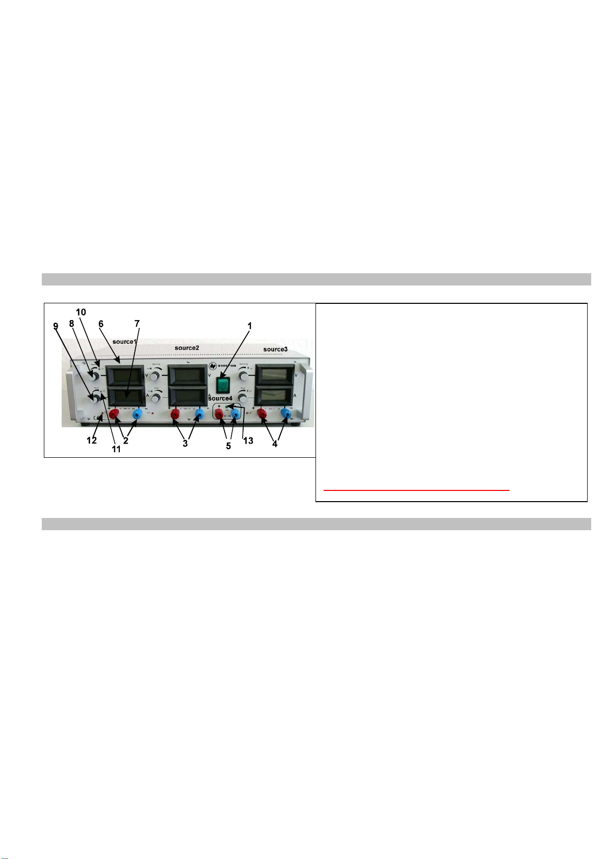
electronic restraint current can as adjustable Current limiting to be used, in order to protect consumers against a too
high power input. In the case of an overloading the output voltage is then lowered accordingly (in the case of short-
circuit on close 0V). With removal of the overload the output voltage adjusted before resets itself automatically. The
respective operating point - voltage - (u) - or restraint current (i) - is displayed by one red LED each. The adjusted
values are readable over 2 LCD displays each. The voltage or current adjustment is made by one wirewount
potenbtiometers ten turns.
2. Safety instructions
2.1 The power supply unit is in protection class I. The safety measures comply with DIN EN61010 and DIN EN
60950. The transformers comply with DIN EN 61558 and have passed the primary/secondary 3.75 kVeff
tests.
2.2 Check that the protective grounding conductor (yellow/green) is not disconnected either from the mains
cable or in the unit, since a disconnected protective conductor may lead to a risk of death. Also check
that the insulation is not damaged or destroyed.
2.3 Power supply units must be kept out of the reach of children!
2.4 In commercial establishments, the safety regulations of the professional trade association for electrical
appliances and equipment must be observed.
2.5 In schools, educational establishments, hobby and independent workshops, there must be careful
supervision that power supply units are operated by trained personnel.
2.6 When opening covers or removing components, apart from when this can be done by hand, live parts
may be exposed. Connections may also be live. Before adjustment, maintenance, repair or replacement of
components, the unit must be disconnected from any power source, if opening the unit is necessary.
Thereafter, if adjustment, maintenance or repair of the open unit when it is connected to the power
supply is unavoidable, this may only be carried out by a specialist engineer familiar with the associated
risks and relevant regulations.
2.7 The capacitors in the unit may still carry a charge, even when the unit is disconnected from any power
supply.
2.8 Check that only fuses of the type and fuse current rating indicated are used as replacements. The use of
repaired fuses or bridging of the fuse holder is not permitted. The unit is protected against overloading
and short-circuits. If the primary fuse melts, there is a serious fault which must be dealt with by a
specialist engineer. After successful repair, a new fuse link can then be installed by an engineer.
2.9 Do not switch on the power supply unit if it has been moved from a cold to a warm place. In unfavorable
conditions, the condensed water released on thawing can destroy your unit or cause life-threatening
voltages at the output terminals. Ensure that the unit can warm up to room temperature without any
adjacent mains current.
2.10 When working with power supply units, you are not permitted to wear any metallic or conductive jewelry
like chains, bracelets, or similar.
2.11 Power supply units are not permitted for use on human beings or animals.
2.12 Series connection of the outputs of one or more mains power units causes life-threatening voltages (>35
VDC).
2.13 The vents on the mains supply units must not be covered! The units must be placed on firm, non-
flammable surfaces, so that the air can enter unhindered. Cooling of the appliances occurs by forced
ventilation.
2.14 The mains supply units and the consumer loads connected to them must not be operated without
supervision. Measures must be taken to ensure the safety and protection of connected loads against
effects caused by the mains power supply unit (e.g. overload, breakdown of the mains appliance) and by
the connected loads themselves (e.g. current consumption above the permitted level).
Warning! Sensitive consumer loads must be protected against damage
by additional external measures!
2.15 In case of fault, power supply units can output voltages over 50V DC, which causes risk,
even if the specified output voltages of the units are lower.
2.16 When working with electrical voltages, only tools expressly permitted for the purpose are to be used.
2.17 The outputs of the power supply units (output bushes/terminals) and leads attached to them must be
protected against direct contact. The leads used must therefore have a sufficient level of insulation
and/or dielectric strength and the contact points must be protected from being touched (safety bushes).
2.18 Connection of uninsulated metallic leads and contacts must be avoided. All of these points must be
protected with suitable, non-flammable insulation material or with other measures. The electrically
conductive components of the connected loads must also be protected from direct contact by
appropriate measures.
2.19 If it becomes apparent that safe operation is no longer possible, the unit must be disabled and secured
against unintentional operation. It is apparent that safe operation is no longer possible when:
- the unit or the mains cable show visible signs of damage
- the unit no longer works
- it has been stored for a long time under unsuitable conditions
- it has been transported under difficult conditions
3. Controls
4. Line-up
a) The euro - connector of the power supply unit into
- Note! With longer operation with max. current consumption or in the case of short-circuit the radiator
box in the power supply unit becomes very heat. An overloading of the power pack is displayed by the red LED "
temperature rise ". At the same time by lowering the original data of the longitudinal automatic controllers of the dc
souurce against thermal overloading one protects.
Pay attention therefore absolutely to a sufficient ventilation of the power supply unit not uncover, it never the
ventilation slots at the device lower surface and at the rear wall the air outlet opening of forced cooling. Absolutely
make sure when connecting a consumer that this is not attached in the switched on status. A switched on consumer can
lead with the link to the output terminals of the power supply unit to a sparking at the connecting terminals, which again
b) Adjustable of the voltage
Turn first the adjusting knob for the current limiting a little to the right side (in the clockwise direction), until the LED (=
light emitting diode) for current limiting is not lighting. In the same instant the LED for the voltage adjustment begins to
light up. Now you can adjust the desired output voltage. The LCD display shows the adjusted output voltage.
c) Adjustment of the current limiting closing it the output
1-power switsch
2 4mm sockets source 1
3 4mm sockets source 2
4 4mm sockets source 3
5 4mm sockets source 3
6 LCD - voltage display source 1
7 LCD current display source 1
8 poti voltage source 1
9 poti current source 1
10 LED constant current operation source 1
11 LED constant current operation source 1
12 LED temperature rise source 1
13 LED output source 4
source 1 to 3 ar in the handling the same !
terminals with switched off power supply unit briefly. Switch then the network on. The display for output current
displays,
depending upon adjustment of the adjusting knob for current limiting, a value. Stop the current limiting, i.e. the "
maximum stream ", with which the power supply unit is to limit. After adjustment they open the short-circuit with
switched off power supply unit, since otherwise an outline spark can develop. Series connection / parallel connection
around optimal base values to achieve and overloading avoid should become preset the sources with for instance the
same original data. Max. 2 sources in series may do geschalten to become.
Technical data
Specification type
3225.71
DC output voltage 0-30V 0-30V 0-40V 5 V
DC output current 0-4A 0-4A 0-3A 5A
CV stability net +5/-7% 2mV 2mV 2mV 5mV
CV stability load 0-100% 40mV 40mV 40mV
50m
V
CV remaining ripple Ueff 2mV 2mV 2mV 2mV
CC stability net +5/-7% 2mA 2mA 3mA
CC stability load 0-100% 3mA 3mA 3mA
CC remaining ripple I eff 2mA 2mA 3mA
correction time load 10-100% 100µs
adjuster Uoutput / Ioutput wirewound potentiometers ten turns / wirewound potentiometers ten turns
dissolution of adjusting 0,10%
characteristic U / I
display for U / I LCD 13 mm 3½-digit LED
Operating temperature 0 - 35°C
output connector 4 mm safety sockets
max. relative humidity 85% by 35°C
AC input voltage 230 V +5% / -7% 48-62Hz
AC testing voltages EN 61010 ; EN 61558-2-4
safety class I
dimensions WxHxD mm 451 x 134 x 324
weight kg 19
electromagnetic compatibility EN 61000-6-3 ; EN 61000-6-2
Statron Gerätetechnik GmbH
Ehrenfried-Jopp-Straße 59
15517 Fürstenwalde
Tel.: (03361) 37 21 01
Fax: (03361) 37 21 03
e-Mail : statron@statron.de
Internet: www.statron.de

Other STATRON Power Supply manuals

STATRON 3231.10 User manual

STATRON

STATRON 3231.10 User manual

STATRON 2256.1 Technical manual

STATRON

STATRON 2256.1 Technical manual

Popular Power Supply manuals by other brands

StarTech.com ATXPOW330HS instruction manual

StarTech.com

StarTech.com ATXPOW330HS instruction manual

Tektronix PS 503S instruction manual

Tektronix

Tektronix PS 503S instruction manual

Avid Technology VENUE E6L manual

Avid Technology

Avid Technology VENUE E6L manual

Pyle PCO850 manual

Pyle

Pyle PCO850 manual

Mastech HY3000M Series user manual

Mastech

Mastech HY3000M Series user manual

Selectronic SP PRO Technical notes

Selectronic

Selectronic SP PRO Technical notes

FOSSIBOT F2400 user manual

FOSSIBOT

FOSSIBOT F2400 user manual

Walrus Audio Aetos instruction manual

Walrus Audio

Walrus Audio Aetos instruction manual

Pepperl+Fuchs FB3205B3 instruction manual

Pepperl+Fuchs

Pepperl+Fuchs FB3205B3 instruction manual

Polk Audio SPS-1 instructions

Polk Audio

Polk Audio SPS-1 instructions

Epson S1F76980 Technical manual

Epson

Epson S1F76980 Technical manual

Pro PRO PS03 product manual

Pro

Pro PRO PS03 product manual

Vector START-IT VEC021ST owner's manual

Vector

Vector START-IT VEC021ST owner's manual

Elektro-Automatik PSI 9000 2U Series operating guide

Elektro-Automatik

Elektro-Automatik PSI 9000 2U Series operating guide

EA-ELEKTRO-AUTOMATIK EA-HV 9000 Series manual

EA-ELEKTRO-AUTOMATIK

EA-ELEKTRO-AUTOMATIK EA-HV 9000 Series manual

Siemens SITOP PSU100L user manual

Siemens

Siemens SITOP PSU100L user manual

Thermaltake W0106RU Specifications

Thermaltake

Thermaltake W0106RU Specifications

Satel APS-412 manual

Satel

Satel APS-412 manual

manuals.online logo
manuals.online logoBrands
  • About & Mission
  • Contact us
  • Privacy Policy
  • Terms and Conditions

Copyright 2025 Manuals.Online. All Rights Reserved.