2 of 86
Contents
1 Introduction ..................................................................................4
1.1 Safety information ...................................................................4
1.2 Description.............................................................................5
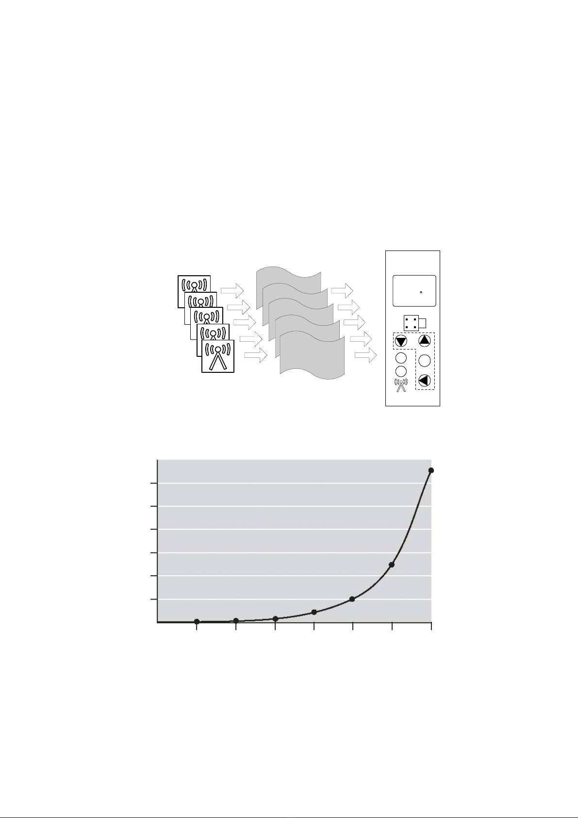
1.3 Block diagram .........................................................................5
2 Identifying the instrument ersion......................................................6
2.1 Type designation .....................................................................6
2.2 Accessories Included.................................................................6
2.3 Accessories ............................................................................6
3 Basics ..........................................................................................7
3.1 Radio technology .....................................................................7
3.2 General information about radio transmission ................................8
3.3 Reception characteristic of the lambda/4 antenna...........................9
3.4 Interferences ........................................................................ 10
3.5 Function o er iew ................................................................. 13
4 Installation.................................................................................. 17
4.1 Installation site and climatic conditions ...................................... 17
4.1.1 Recei er ....................................................................... 17
4.1.2 Antenna........................................................................ 17
4.2 Dimensions........................................................................... 18
4.2.1 Recei er WRX900............................................................ 18
4.2.2 Lambda/4 antenna .......................................................... 18
4.2.3 Antenna wall holder for lambda/4 antenna ........................... 18
4.3 Recei er installation........................................................... 19
4.4 Fitting the antenna ................................................................ 20
4.4.1 Antenna installation directly on the recei er......................... 20
4.4.2 Antenna installation on the antenna wall holder .................... 20
5 Electrical connection..................................................................... 20
5.1 Installation notes ................................................................... 20
5.2 Connection diagram................................................................ 21
6 Display and key functions ............................................................... 23
6.1 Normal display (measured alues and signal quality) ...................... 23
6.2 Commissioning/start-up le el (In) (allocating the probe ID to a channel)
............................................................................................... 25
6.3 Parameter le el (PA) (Parameter configuration)............................ 27
6.4 Light diodes (independent of le el)............................................ 29
7 Recei er operation ....................................................................... 30
7.1 Normal display (ND)................................................................ 31
7.2 Channels and their Display measured alues ................................ 31
7.3 Display signal quality of the probes recei ed................................ 32
7.4 Changing to other Changing le els............................................. 33
7.5 Code interrogation ................................................................. 34
8 Configuration of the recei er .......................................................... 37