Staubli 90B family User manual

© Stäubli Faverges 2004
Arm - RX series 90B family
Characteristics
D18326204C - 11/2004

2D18326204C - 11/2004
The specifications contained in the present document can be modified without notice. Although
all necessary precautions have been taken to ensure that the information contained in this
document is correct, STÄUBLI cannot be held responsible for any errors or omissions found in
the illustrations, drawings and specifications contained in the said document.

D18326204C - 11/2004 3
TABLE OF CONTENTS
1 - DESCRIPTION.......................................................................................7
1.1. GENERAL PRESENTATION.................................................................................................... 9
1.2. DESIGNATION OF ROBOTS OF THE RX SERIES 90B FAMILY ......................................... 11
1.3. GENERAL CHARACTERISTICS............................................................................................ 11
1.3.1. Overall dimensions...................................................................................................... 11
1.3.2. Work environment ....................................................................................................... 11
1.3.3. Weight ......................................................................................................................... 11
1.4. PERFORMANCE .................................................................................................................... 13
1.4.1. Torque limits................................................................................................................ 13
1.4.2. Amplitude, speed and resolution ................................................................................. 13
1.4.3. Modification of amplitudes........................................................................................... 13
1.5. LOAD CAPACITY – MECHANICAL INTERFACE ................................................................. 15
1.5.1. Load capacity .............................................................................................................. 15
1.5.2. Attachment of additional load on forearm.................................................................... 17
1.5.3. Additional load diagrams ............................................................................................. 19
1.6. USER CIRCUIT ....................................................................................................................... 21
1.7. RELEASING JOINT BRAKE .................................................................................................. 21
1.8. PNEUMATIC AND ELECTRIC CIRCUITS (EXCEPT FOR CLEAN ROOM APPLICATION) ... 23
1.8.1. Pneumatic circuit .........................................................................................................23
1.8.2. Electric circuit .............................................................................................................. 23
1.9. PNEUMATIC AND ELECTRIC CIRCUITS CLEAN ROOM APPLICATION........................... 25
1.9.1. Pneumatic circuit .........................................................................................................25
1.9.2. Electric circuit .............................................................................................................. 25
1.10. PRESSURIZATION UNIT FOR DUSTY ENVIRONMENTS.................................................... 27
1.10.1. Purpose ....................................................................................................................... 27
1.10.2. Installation ................................................................................................................... 27
1.11. SAFETY .................................................................................................................................. 29
2 - ON-SITE PREPARATION....................................................................31
2.1. WORKING SPACE ................................................................................................................. 33
2.2. ATTACHMENT........................................................................................................................ 33

4D18326204C - 11/2004

D18326204C - 11/2004 5
3 - INSTALLATION ...................................................................................35
3.1. ARM PACKAGING ................................................................................................................. 37
3.2. HANDLING OF PACKING ...................................................................................................... 37
3.3. UNPACKING AND INSTALLATION OF ARM ....................................................................... 37
3.4. INSTALLATION OF ARM ....................................................................................................... 39
3.4.1. Installation of arm on floor ........................................................................................... 39
3.4.2. Installation of arm on ceiling........................................................................................ 39
3.4.3. Mounting floor quality .................................................................................................. 39
3.5. SPRING TENSION.................................................................................................................. 41

6D18326204C - 11/2004

Chapter 1 – Description
D18326204C - 11/2004 7
CHAPTER 1 –
DESCRIPTION

8D18326204C - 11/2004
Figure 1.1
B
A
C
D
E
F
3
4
5
2
1
6
RX 90
RX 90
R

Chapter 1 – Description
D18326204C - 11/2004 9
1.1. GENERAL PRESENTATION
The arm consists of segments or members interconnected by joints (figure 1.1).
Each joint comprises an axis around which two members pivot.
The movements of the robot’s joints are generated by brushless motors coupled to resolvers. Each of these
motors is equipped with a parking break.
This reliable and robust assembly associated with an innovative counting system allows the absolute
position of the robot to be known at all times.
The arm assembly is sufficiently flexible and is able to perform a great variety of applications.
Example: Handling of loads, assembly, process, application of adhesive beads, control/check and clean
room applications. This list is not restrictive: for further information, please consult us.
The various elements of the robot’s arm are: the base (A), the shoulder (B), the arm (C), the elbow (D), the
forearm (E) and the wrist (F) (figure 1.1).
The robot arm assembly thus contains the motorization, brakes, motion transmission mechanisms, cable
bundles, pneumatic and electric circuits for the user and the counterbalance system.
Of simple construction, the RX90B arm assembly consists of a rigid and encased structure (protection IP65
to standard NF EN 60529) to protect it against external aggressions. Its design is based on transmission
modules: JCS (STÄUBLI Combined Joint) used on joints 1, 2, 3 and 4 (figure 1.1).
The wrist consists of joints 5 and 6 (figure 1.1).
Arm balance is performed by an integrated spring system. The arm has a built-in spring counterbalance
system giving an attractive low weight system.

10 D18326204C - 11/2004
Figure 1.2
Figure 1.3

Chapter 1 – Description
D18326204C - 11/2004 11
1.2. DESIGNATION OF ROBOTS OF THE RX SERIES 90B FAMILY
1.3. GENERAL CHARACTERISTICS
1.3.1. OVERALL DIMENSIONS (figures 1.2 and 1.3)
Vertical cable outlet
Horizontal cable outlet
1.3.2. WORK ENVIRONMENT
• Working temperature: + 5°C to + 40°C (according to standard(s) and/or directive(s): NF EN 60 204-1)
• Humidity: 30% to 95% max. non-condensing (according to standard(s) and/or directive(s): NF EN 60
204-1)
• Altitude: 2000 m max
• Vibrations: please consult us
Clean room application: Cleanliness class ISO 4 according to standard ISO 14644-1
1.3.3. WEIGHT
RX 9 0 B CR
(1) (2) (3) (4) (5)
(1) RX family arm
(2) Maximum reach between joints 2 and 5 expressed in decimeters:
dimension + dimension
(3) Number of active joints:
• 0 = 6 active joints.
• 5 = 5 active joints, geometry being conserved.
(4) RX family changed to "B".
(5) Upper case letters to indicate an option.
• L = extended forearm: dimension + dimension (figure 1.3).
• CR = clean room application.
These letters can be combined.
Example: LCR = extended forearm clean room application.
In the manual, the following terminology is used:
Standard arm: for arm with standard geometry (figure 1.2).
Long arm: for arm with different geometry where forearm is extended (figure 1.3).
5-joint arm: for arm with 5 active joints.
CAUTION:
It may be necessary to perform a warm-up cycle before nominal performances are
obtained.
STANDARD ARM LONG ARM 5-JOINT ARM LONG 5-JOINT ARM
111 kg 113 kg 106 kg 107 kg
A B
A C
1
2

12 D18326204C - 11/2004
Figure 1.4

Chapter 1 – Description
D18326204C - 11/2004 13
1.4. PERFORMANCE
1.4.1. TORQUE LIMITS
1.4.2. AMPLITUDE, SPEED AND RESOLUTION
Low speed for manual control pendant:
• cartesian mode 250 mm/s
• revolute mode: 10% of nominal speeds
Maximum Cartesian speed: 2 m/s
1.4.3. MODIFICATION OF AMPLITUDES
The arm is installed to obtain maximum angular amplitudes.
The amplitude of the joints can be voluntarily limited by the "software" (see chapter on programming). Also,
the position of the mechanical travel limiters on joints 1, 2 and 3 and of the electrical travel limiters on joints
1 and 2 can be modified in a certain number of positions (for modification, please consult STÄUBLI).
See figure 1.4 Brake release access area
Area accessible in righty configuration
STANDARD ARM LONG ARM
Work envelope
R.M max. reach between joints 2 and 5 900 mm 1100 mm
R.m min. reach between joints 2 and 5 289 mm 401 mm
R.b reach between joints 3 and 5 450 mm 650 mm
Maximum speed at load center of gravity 11 m/s 12.6 m/s
Repeatability at constant temperature ± 0.02 mm ± 0.025 mm
REFERENCE JOINT
JOINT 5 (Z6)JOINT 6 (Z7)
Static torque (Nm) 24 (1) 14 (2) 10 (1) if joint 6 torque = 0
(2) for maximum torque
on joint 6
Peak torque (Nm) 100 (1) 57 (2) 43
Joint 1 2 3 4 (1) 56
(1) For 5-joint arms, joint
4 is fixed. Joint 5
corresponds to joint
4 and joint 6 to joint 5
of the software.
(2) Multiturn version
available as an
option.
(3) without axis 5
interaction.
Amplitude (°) 320 275 285 540 225 540 (2)
Working range
distribution (°)
A
± 160
B
± 137.5
C
± 142.5
D
± 270
E
+120
-105
F
± 270
Nominal speed (°/s) 236 200 286 401 320 580
Maximum speed (°/s) 356 356 296 409 800 1125 (3)
Angular resolution
(°.10-3)
0.87 0.87 0.72 1 1.95 2.75
CAUTION:
In some arm configurations, the maximum joint speeds can be reached only if payloads
and inertias are reduced.
1
2

14 D18326204C - 11/2004
Figure 1.5

Chapter 1 – Description
D18326204C - 11/2004 15
1.5. LOAD CAPACITY – MECHANICAL INTERFACE
Mechanical interface
End-effector
The end-effector is not supplied with the robot arm assembly; its design depends on the robot’s specific
applications. All studies can be undertaken in cooperation with STÄUBLI to obtain optimum performance
without exceeding the robot arm assembly load limits.
The end-effector is installed on the mechanical interface of the wrist dimensions of which are given on
figure 1.5.
Attachment by 4 M6 screws item , Class 12-9, torque 16.7 Nm ± 1.2 Nm.
Indexing by pin item , diameter 6.
Mechanical interface designation:
ISO 9409 - 1 - A40 as per Standard ISO 9409 - 1 : 1996 (F)
(except the localization of the 4 M6 threaded holes)
1.5.1. LOAD CAPACITY (figure 1.5)
Load characteristics:
Load center of gravity position : z = 150 mm from centerline of joint 5 and x = 75 mm from centerline of
joint 6 (figure 1.5).
(1) in all configurations and taking maximum inertias into account. See table below.
(2) under reduced speed and acceleration conditions:
For CS7B: SP60, ACC(8) 50, 50
For CS8: VEL = 60%, ACC = 30%, DEC = 30%
CAUTION:
Length of end-effector attaching screws is limited to avoid all interference with the wrist
(figure 1.5).
Load capacity Standard arm Long arm
At nominal speed (1) 6 kg 3.5 kg
At reduced speed (1) 9 kg 6 kg
In some configurations (consult
us)
12 kg 9 kg
NOMINAL INERTIAS (kg.m²) MAXIMAL INERTIAS (kg.m²) (2)
STANDARD ARM LONG ARM STANDARD ARM LONG ARM
For joint 5 0.135 0.080 0.675 0.400
For joint 6 0.034 0.020 0.170 0.100
CAUTION:
The nominal values can be exceeded to a certain extent but imply a limitation to the
speed and the acceleration of the arm. If these limits are to be exceeded, please consult
STÄUBLI.
1
2
B
4
B
3
B
M

16 D18326204C - 11/2004
Figure 1.6
Effective tapped
depth : 8 mm

Chapter 1 – Description
D18326204C - 11/2004 17
1.5.2. ATTACHMENT OF ADDITIONAL LOAD ON FOREARM
An additional load can be attached to the forearm using 4 M5 screws; maximum torque is 7 Nm.
Position of 4 M5 tapped holes: See figure 1.6.
DIMENSIONS STANDARD ARM LONG ARM
A 167.5 ± 1 mm 272 ± 1 mm
B6° 4.5°
CAUTION:
The additional load depends on nominal load (see next page); in all cases, do not
exceed load characteristics.

18 D18326204C - 11/2004
Figure 1.7 Figure 1.8
Figure 1.9 Figure 1.10

Chapter 1 – Description
D18326204C - 11/2004 19
1.5.3. ADDITIONAL LOAD DIAGRAMS
These diagrams can be used to determine the additional load which can be attached to the forearm
depending on its center of gravity position from joint 3 and the load attached to the mechanical interface of
the wrist.
(1) Reduced speeds:
For CS7B: SP60, ACC(8) 50, 50
For CS8: VEL = 60%, ACC = 30%, DEC = 30%
Additional load (kg)
Additional load center of gravity position (m) from centerline of joint 3.
The additional load center of gravity position is at 0.25 m max. from the centerline of joint 4.
Load attached to the mechanical interface of the wrist.
150 mm from centerline of joint 5 and 75 mm from centerline of joint 6.
Figure 1.7: for standard RX90B
Figure 1.8: for standard RX90B with reduced speeds (1)
Figure 1.9: for RX90B long arm
Figure 1.10: for RX90B long arm with reduced speeds (1)
B
M1
B
M2
B
3

20 D18326204C - 11/2004
Figure 1.11
Figure 1.12
R
RX 90
R
E10
B1
A1
B2
A2
P2
P1
P2
JOC
2
1
3
EV1
EV2
4
5
R
R
E10
B1
A1
B2
A2
P2
EV2
P1
P2
JOC
2
1
3
EV1
5
4
Table of contents
Other Staubli Robotics manuals
Popular Robotics manuals by other brands
Dr Robot
Dr Robot Jaguar V4 user guide
dji
dji Robomaster S1 quick start guide
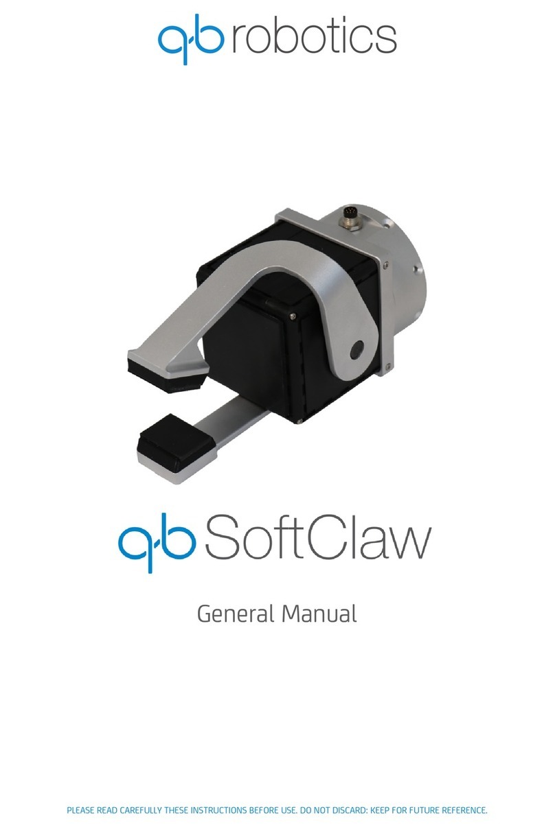
QB Robotics
QB Robotics qb SoftClaw General manual

ShenZhen Yuejiang Technology
ShenZhen Yuejiang Technology Dobot Vision Kit installation guide

V-tech
V-tech JOTBOT 5537 instruction manual

TT Robotix
TT Robotix TTR-SB Seawolf instruction manual
