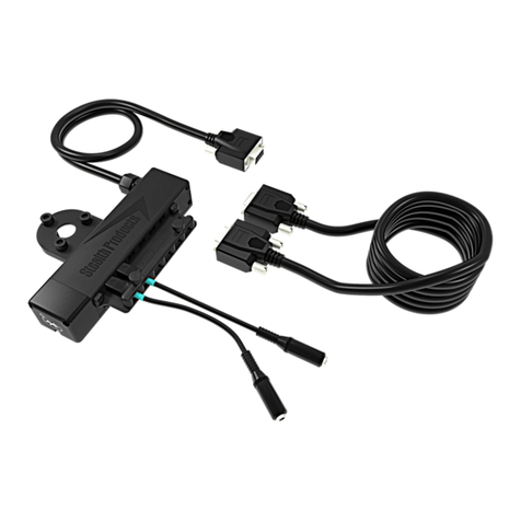
Stealth Products i-Drive 4.0 Guide

USER MANUAL
i-Drive®4.0
Stealth’s User Manual and Maintenance Guide for i-Drive 4.0
Alternative Control with Bluetooth® Wireless Technology
Alternative Drive Controls

i
Customer Satisfaction 1.0
Stealth Products strives for 100% customer satisfaction. Your complete
satisfaction is important. Please contact us with feedback or suggested
changes that will help improve the quality and usability of our products.
You may reach us at:
General
Read and understand all instructions prior to the use of the product. Failure to
adhere to any recommendations and warnings in this document may result in
property damage, injury, or death. Product misuse due to failure of following
any instructions will void the warranty.
Immediately discontinue use if any function is compromised, parts are missing,
loose, or shows signs of excessive wear. Consult with your supplier for repair,
adjustment, or replacement.
If this document contains information you do not understand, or there are
concerns about safety or operation, contact your supplier.
Google, the Google Logo and Google Play Logo are registered trademarks of Google Inc. Apple Logo
and the AppStore Logo are registered trademarks of Apple Inc.
The Bluetooth® word mark and logos are registered trademarks owned by Bluetooth SIG, Inc. and
any use of such marks by Stealth Products, LLC is under license. Other trademarks and trade names
are those of their respective owners.
MDSS GmbH
Schiffgraben 41
30175 Hannover, Germany
Stealth Products, LLC
104 John Kelly Drive, Burnet, TX 78611
Phone: (512) 715-9995 Toll Free: 1(800) 965-9229
Fax: (512) 715-9954 Toll Free: 1(800) 806-1225

ii
Important Information 2.0
Important Information!
All persons responsible for fitting, adjustment, and daily use of the devices
discussed in these instructions must be familiar with and understand all safety
aspects of the devices mentioned. In order for our products to be used
successfully, you must:
Read and understand all instrucons and warnings.
Maintain our products according to our instrucons on care and maintenance.
Devices should be installed and adjusted by a trained technician.
All programming and configurations MUST be completed by a certified ATP or
trained technician.
This user manual contains programming instructions and statements that are
meant to be followed by a certified ATP or trained technician.
Supplier Reference
Supplier:
Telephone:
Address:
Purchase Date:
Model:

iii
Introduction 3.0
Before you install or begin using this product, it is important that you read and
understand the content of this user manual and its warnings. This user manual
will guide you through the options and possibilities with the product.
Information in this manual is written with the expressed intent of use with
standard configurations. They also contain important safety and maintenance
information, as well as describe possible problems that can arise during use.
For further assistance, or more advanced applications, please contact your
supplier or Stealth Products at (512) 715-9995 or toll free at 1-800-965-9229.
Always keep the user manual in a safe place so it may be referenced as
necessary.
All information, pictures, illustrations, and specifications are based on the
product information that was available at the time of printing. Pictures and
illustrations shown in this manual are representative examples and are not
intended to be exact depictions of the various parts of the product.
Ordering Documentation
You can download additional copies of this user manual on the Stealth website:
https://stlpro.site/stealth-docs
and search: i-Drive 4.0 User Manual in the search bar at the top of the page.
CAUTIO N
These products are designed to be fitted, applied, and installed exclusively by a
health care professional trained for these purposes. The fitting, application and
installation by a non-qualified individual could result in serious injury.

iv
Warranty 4.0
Our products are designed, manufactured, and produced to the highest of
standards. If any defect in material or workmanship is found, Stealth Products
will repair or replace the product at our discretion. Any implied warranty,
including the implied warranties of merchantability and fitness for a particular
purpose, shall not extend beyond the duration of this warranty. Stealth
Products, LLC does not warrant damage due to, but not limited to:
Misuse, abuse, or misapplicaon of products.
Modicaon of product without wrien approval from Stealth Products, LLC.
Any alteraon or lack of serial number, where applicable, will automacally
void this warranty.
Stealth Products, LLC is liable for replacement parts only.
Stealth Products, LLC is not liable for any incurred labor costs.
No person is authorized to alter, extend, or waive the warranties of Stealth
Products, LLC.
Stealth Products warrants against failure due to defective materials
or workmanship:
Covers: 2 years
Hardware: 5 years
Electronics: 3 years
In Case of Product Failure
In the event of product failure covered by our warranty, please follow the
procedures outlined below:
1. Call Stealth at +1 (512) 715-9995 or toll free +1-800-965-9229.
2. Request the Returns Department or obtain an RA from the Returns Department and
follow department or documentaon instrucons.

v
FCC Statement 5.0
Federal Communications Commission (FCC) Statement (USA)
FCC ID: 2AJXVIDHBT500
FCC RF Exposure Statement
This device meets the FCC requirements for RF exposure in public or
uncontrolled environments.
This device complies with FCC part 15 FCC Rules. Operation is subject to the
following two conditions:
1. This device may not cause harmful interference, and
2. This device must accept any interference received, including interference that may cause
undesired operaon.
FCC Warning
Changes or modifications not approved by Stealth Products, LLC could void the
user’s authority to operate the equipment.
Note: This equipment has been tested and found to comply with the limits for
Class B digital device, pursuant to part 15 of the FCC rules. These limits are
designed to provide reasonable protection against harmful interference in a
residential installation. This equipment generates, uses, and can radiate radio
frequency energy and, if not installed and used in accordance with the
instructions, may cause harmful interference to radio communications. However,
there is no guarantee that interference will not occur in a particular installation.
If this equipment does cause harmful interference to radio or television
reception, which can be determined by turning the equipment off and on, the
user is encouraged to try to correct the interference by one or more of the
following measures:
Reorient or relocate the receiving antenna
Increase the separaon between the equipment and receiver
Connect the equipment into an outlet on a circuit dierent from that to which the receiver
is connected
Consult the dealer or an experienced radio/TV technician for help

vi
Table Of Contents 6.0
1.0 Customer Satisfaction.................................................................................... i
2.0 Important Information ................................................................................. ii
3.0 Introduction .................................................................................................. iii
4.0 Warranty........................................................................................................ iv
5.0 FCC Statement ............................................................................................... v
6.0 Table Of Contents ........................................................................................ vi
7.0 Warning Labels ........................................................................................... viii
7.1 Warning Labels ........................................................................................................... viii
7.2 Limited Liability........................................................................................................... viii
7.3 Testing............................................................................................................................ viii
8.0 Index ................................................................................................................ 1
9.0 System Requirements .................................................................................... 3
9.1 i-Drive Minimum System Requirements .............................................................. 3
9.2 i-Drive Bluetooth Minimum System Requirements ......................................... 3
9.3 EMC Requirements ....................................................................................................... 3
10.0 Design and Function................................................................................... 4
10.1 Intended Use ............................................................................................................... 4
10.2 Features......................................................................................................................... 4
10.3 Factory Settings........................................................................................................... 5
11.0 Parts and Accessories .................................................................................. 6
11.1 i-Drive Packages Available...................................................................................... 6
11.2 Replacement/Additional Parts Available........................................................... 6
12.0 Advanced Programming Software ........................................................... 7
12.1 i-Drive Advanced Programming Software........................................................ 7
12.2 Getting Started ........................................................................................................... 7
12.3 Downloading the i-Drive Software to Your PC.............................................. 7
12.4 Connecting to the i-Drive ....................................................................................... 9
12.5 Running Real Time Diagnostics ..........................................................................10

vii
Table Of Contents 6.0
12.6 Help Feature............................................................................................................... 11
12.7 Closing the i-Drive Programming Software .................................................. 12
13.0 i-Drive Mobile App Installation ...............................................................13
13.1 Downloading the i-Drive Bluetooth® Application .................................... 13
For iPhone Users................................................................................................ 13
For Android Users ............................................................................................. 14
13.2 Opening the i-Drive Bluetooth® App.............................................................. 15
13.3 Diagnostics................................................................................................................ 17
14.0 Testing ........................................................................................................ 18
14.1 Operational Test ...................................................................................................... 18
14.2 Test Drive.................................................................................................................... 18
15.0 First Time Use ............................................................................................19
15.1 Dealer Assistance .................................................................................................... 19
15.2 User Testing .............................................................................................................. 19
15.3 Conditions Of Use .................................................................................................. 19
16.0 Maintenance................................................................................................20
16.1 Care And Maintenance ........................................................................................ 20
16.2 Safety ......................................................................................................................... 20
16.3 Technical Data ........................................................................................................... 20

viii
Warning Labels 7.0
Warning Labels 7.1
Warnings are included for the safety of the user, client, operator and property. Please
read and understand what the signal words SAFETY, NOTICE, CAUTION, WARNING
and DANGER mean, how they could affect the user, those around the user, and property.
Limited Liability 7.2
Stealth Products, LLC accepts no liability for personal injury or damage to property that
may arise from the failure of the user or other persons to follow the recommendations,
warnings, and information in this manual.
Stealth Products does not hold responsibility of final integration of final assembly of
product to end user. Stealth Products is not liable for user death or injury.
Testing 7.3
Initial setup and driving should be done in an open area free of obstacles until the user is
fully capable of driving safely.
The i-Drive should always be programmed and tested without any person sitting in the
wheelchair until every alteration of the physical installation or adjustment is complete.
NOTICE
Identifies important information not related to injury, but
possible property damage.
SAFETY
Indicates steps or instructions for safe practices, reminders of
safe procedures, or important safety equipment that may
be necessary.
CAUTI ON Identifies a potential situation which (if not avoided) will
result in minor to moderate injury,and property damage.
WA RNIN G Identifies a potential situation which (if not avoided) will
result in severe injury, death,and property damage.
DANGER Identifies an imminent situation which (if not avoided) will
result in severe injury, death,and property damage.

1
Index 8.0
Configurable Parameters-There is only one additional configurable parameter in the
i-Drive configuration application for switched inputs, sensor sensitivity.
Sensor Sensitivity–This parameter shifts the position of the switch no-change region. A
higher value therefore means that a switch will always be interpreted as ON, whereas a
lower value means that a switch will almost always be interpreted as OFF.
Proportional Input Controls–Proportional inputs can be assigned to proportional
functions such as forward/reverse (F/R) and left/right (L/R). If the proportional input is
determined to be nonzero it will be output to the chair.
Configurable Parameters-Proportional inputs have the following additional configurable
parameters. Not that it is best to handle these by first calibrating the input through
‘Joystick Calibration’ in the i-Drive configuration applications.
Dead Band Region-This may be used to define the dead band low and high relative to
the proportional limits minimum, center, and maximum. Calibration is required in order
to calculate the center voltage.
Calibration-This feature is accessible directly through Config Mode rather than the
Channels menu after a proportional function has been assigned. The calibration
procedure calculates the center voltage as well as the recommended values for the
proportional region and dead band region based on user input.
Linked Left-Right-The left and right inputs can be linked so the chair moves forward
when both are engaged. This feature may be enabled under the sensor settings for ‘Left’
or ‘Right’ in the i-Drive Mobile apps, or by selecting ‘Linked Left and Linked Right’ to the
respective channels in the i-Drive Programmer Windows application
Multi-Tap-The i-Drive system implements an extended double-tap timer to
accommodate clients who need a longer double-tap input time. The double-tap exten-
sion time is shared with the triple-tap activation time in mouse mode, hence the name
‘Multi-Tap’.

2
Index 8.0
Configurable Parameters (Mouse Emulation)-The multi-tap feature is configurable under
‘Multi-Tap’ in the i-Drive configuration applications. Two parameters are configurable,
Input Delay and Output Speed.
Input Delay-This is the longest time that the i-Drive system will wait for additional taps
after the first tap is detected. It may be set manually or calibrated using the ‘Calibrate’
option in the i-Drive Configuration applications. No single or double tap input will be
acknowledged until after time has expired, thus, this delay should be set as short as
possible based on how fast the user can reliably tap the input.
Output Speed-This is the speed of the multi-tap pulse that is sent to the chair. The i-Drive
system simulates a user inputting a multi-tap to the chair at a faster rate. This may set
manually in the i-Drive configuration applications.

3
System Requirements 9.0
i-Drive Minimum System Requirements 9.1
i-Drive Bluetooth Minimum System Requirements 9.2
EMC Requirements 9.3
Electromagnetic compatibility (EMC) up to 20 V/m
Processor 1 GHz
RAM1 512 MB
Disk Space 7 MB
Operating System 1 Windows Vista SP2 or later (32-bit or 64-bit)
Additional Requirements Internet access and a valid DAD account for
configuration features, .NET Framework 4.5.1
Processor 1 GHz
RAM1 512 MB
Disk Space 7 MB
Operating System Windows 8 or later (32-bit or 64-bit)
Screen Resolution 1024 x 768 or larger (1280 x 720 or larger
recommended)
Additional Requirements Internet access and a valid DAD account for
configuration features, Bluetooth adapter, .NET
Framework 4.5.1
WARNI NG
Exposure to water can result in a shortage and intermittent failure of the device.

4
Design And Function 10.0
Intended Use 10.1
The i-Drive control system allows the use of alternative input devices to drive an electric
wheelchair. Up to six input devices such as an egg switch, proximity pad, Sip & Puff,
head array, and tray array are supported. The i-Drive system relies primarily on
two types of input interpretations: switched and proportional.
The interpretation used for each channel is dependent on the function assigned to it.
The i-Drive system includes software that can display real-time diagnostics data,
such as the desired direction of motion, to help setup and verify a configuration.
Features 10.2
Bluetooth® Programming App with full wireless programming capabilies.
Smart Input Connecons-sensors and mechanical switches can now be placed at any port.
Easy interface exchange capability
Real-me diagnoscs data
NOTICE
Existing dongles will not work with the new 4.0 interface, however 4.0 dongles
will work with the 3.0 interface.
SAFETY
Chair calibration has been successfully tested on QLogic 2, QLogic3, and R-Net
Omni enhanced displays. Call your sales representative for compatibility with
other electronics.

5
Design And Function 10.0
Factory Settings 10.3
The i-Drive 4.0 has the capability of taking inputs from mechanical switches,
proximity sensors, fiber optic sensors, joysticks, and Sip & Puff modules (all
which can be configured by a certified technician). With the new i-Drive
interface, there is the capability of running diagnostics with the associated
Advanced Programming Software from your PC by using the supplied USB
cable, and now also includes the option to download the i-Drive App and
program the interface directly from your phone via Bluetooth®wireless
technology.
NOTICE
The software will not read correctly if a non Bluetooth® dongle is plugged into
a port. Any dongle plugged into the interface MUST be Bluetooth®.
NOTICE
All connectors have blue heat shrink on the cord for visual reference and easy
recognition.
Port 1
Port 6
Port 1 Right
Port 2 Reverse
Port 3 None
Port 4 Mode
Port 5 Forward
Port 6 Left Port 1

6
Parts And Accessories 11.0
i-Drive 4.0 Packages Available 11.1
Replacement/Additional Parts Available 11.2
All packages include 2 mono plug dongles, an extension cable, and a USB cable
Part Number Description
IDHBT200-1 i-Drive Tri-Array Head Support, includes 3 Proximity Sensors,
non-proportional, with egg switch for reset mode change and i-Drive
Bluetooth® Interface
IDHBT210-1 i-Drive Tri-Array Head Support with Sip & Puff, includes 3 Proximity
Sensors, with egg switch for reset mode and i-Drive Bluetooth® Interface
IDHBT250-1 i-Drive Pediatric Tri-Array Head Support, includes 3 Proximity Sensors,
non-proportional with egg switch for reset mode change and i-Drive
Bluetooth® Interface
IDHBT260-1 i-Drive Pediatric Tri-Array Head Support with Sip & Puff, includes 3
Proximity Sensors, non-proportional, with egg switch for reset mode
change and i-Drive Bluetooth®Interface
IDHBT300-1 i-Drive Pro Series Head Support, includes 3 Proximity Sensors, occipital
pad, swing away hardware for left and right side, 2 spot pads with egg
switch for reset mode change and i-Drive Bluetooth® Interface
IDHBT310-1 i-Drive Pro Series Head Support with Sip & Puff, includes 3 Proximity
Sensors, non-proportional, with egg switch for reset mode change and
i-Drive Bluetooth®Interface
IDHBT350-1 i-Drive Pediatric Pro Series Head Support, includes 3 Proximity Sensors,
non-proportional, with egg switch for reset mode change and
i-Drive Bluetooth® Interface
IDHBT360-1 i-Drive Pediatric Pro Series Head Array with Sip & Puff, includes 3
Proximity Sensors, non-proportional, with egg switch for reset mode
change and i-Drive Bluetooth® Interface
Part Number Description
IDHBT500-17MM i-Drive Bluetooth® Interface for 17mm Ball Mount
IDHBT500-1 i-Drive Bluetooth® Interface for 1” Ball Mount
IDHBT500 i-Drive Bluetooth® Interface

7
Advanced Programming Software 12.0
i-Drive Advanced Programming Software 12.1
The i-Drive’s Advanced Programming Software is not required to operate the
drive control, but is available to ensure a customized fit and driving experience.
Programming the i-Drive is simple. By connecting a tablet or smartphone and
using the i-Drive Advanced Programming Software application you can:
Dynamic Channel Assignment– any port can control any of the outputs
Adjust Acvaon Proximity– Change the range of moon required for switch acvaon
Provide an adjustable double tap feature that extends chair double tap limits
Conguraon– Programmed by Bluetooth or PC
Getting Started 12.2
The first step to begin use of the i-Drive 4.0 is downloading the software. The
link to download the software is listed on page 7. If there are any difficulties
obtaining the software, contact Stealth Products, LLC.
After the software has been installed onto your device, you can begin utilizing
the Advanced Programming Software. Launch the “i-Drive Programmer”
application on your device, and with the provided USB to Mini-USB cable,
connect the i-Drive to your PC or Tablet. Allow time for the i-Drive to make a
full connection with your computer.
Downloading the i-Drive Software 12.3
To program the i-Drive from your PC, the Advanced Programming Software™
will need to be downloaded from the Stealth Products website:
https://stealthproducts.com/idrive/download/
The USB interface enables an external device to communicate with i-Drive with
the use of a virtual communications port. There is no authentication
requirement to gain access.

8
Advanced Programming Software 12.0
The Bluetooth interface enables an external device to communicate with the
i-Drive via a secure Bluetooth connection.
*PC views shown.
In order to connect to the i-Drive to the software, the serial number from the
interface must be entered. The figure below indicates the location of the serial
number on the interface.

9
Advanced Programming Software 12.0
Connecting To The i-Drive 12.4
After adequate time is given to allow the i-Drive to connect to your computer
and you have launched the application, click the Connect button.
NOTICE
If may be required to change the COM in the drop-down menu next to the
Connect button.
NOTICE
When the i-Drive is connected to the software, the serial number of the
interface, the firmware version of the software, and the system voltage should
appear on the bottom of the screen.

10
Advanced Programming Software 12.0
Running Real Time Diagnostics 12.5
To begin the Diagnostics, click the Diagnostics button on the left of the screen.
A. Mode Switch activation
B. Left, Right, Forward & Reverse activation
C. Corresponding i-Drive port when switch is pressed
D. Double Tap Calibration
Diagnostics Feature
With real time Diagnostics, you are able to observe pad behavior as the head
array is activated by the user. Ensure the operating system is operating properly.
CAUTIO N
Double Tap needs to be enabled in the Configuration menu Double Tap Settings
before Double Tap Calibration can be used.
A
B
C
D

11
Advanced Programming Software 12.0
Help Feature 12.6
Clicking the Help button will activate help. When Help is active, the help button
will be green and a question mark (?) will be displayed next to your cursor. With
Help active, clicking buttons and menu items will pop up with an explanation of
what the clicked object is and how it can be utilized. To disable Help, click on
the Help button again.
NOTICE
The Help button will appear black when inactive and green when active.
Other manuals for i-Drive 4.0
1
Table of contents
Other Stealth Products Controllers manuals
