HUAYUAN MAM860 User manual

MAM860 (IV)
Oil-Free Scroll Air Compressor Controller
Operation Manual

Contents
I. Introduction ................................................................................................................................................... 1
Ⅱ. Description of Keys.................................................................................................................................... 1
Ⅲ. Status Display and Operation ..................................................................................................................... 3
Ⅳ. Viewing Running Parameters..................................................................................................................... 4
Ⅴ. List of User Parameters .............................................................................................................................. 5
Ⅵ. List of Manufacturer Parameters................................................................................................................ 8
Ⅶ. Adjustment Parameters............................................................................................................................. 11
Ⅷ. Operation Authority and Password Management .................................................................................... 14

1
1. Introduction
I. Introduction
Huayuan oil-free scroll air compressors are equipped with a microcomputer controller for intelligent
automatic operation of air compressors, including automatic pressure control, real-time display of
failure messages, protection shutdown, networking group control, etc. Four lines of text can be
displayed on the LCD screen where operators can set parameters and check operating status of
compressor via man-machine dialog.
Ⅱ. Description of Keys
Power
Run
Fault

2
2. Description of Keys
Start key
When the air compressor is in standby mode, press this key to
start it;
In connection mode,
the air compressor with a communication
address of 1 serves as the host,
press this key to start the air
compressor, and the connection control starts at the same time.
Stop key
When the air compressor is running, press this key to stop it;
When a host is used in connection mode, press this key to stop
the air compressor and the connection control stops at the same
time.
When the equipment is in shutdown state, long press this key to
display the information of software version.
Load /
Unload key
When the air compressor is running, this key serves as Load /
Unload key.
In setup mode, press this
key for confirmation and save input
data.
Confirm key
Down key
When viewing parameters, press this key to move the scroll bar
down;
When modifying data, press this key to decrease the flashing
data value in the current position.
Dec key
Up key
When viewing parameters, press this key to move the scroll bar
up;
When modifying data, press this key to increase the flashing
data value in the current position.
Inc key
Shift key
When modifying data, this key serves as Shift key and press it
to move the blinking cursor to the next bit;
When selecting menus, press this key to enter the lower level
menu of the current menu.
If the current menu does not have a lower-level menu, enter the
setup mode of the current menu, and the data on the current
menu starts to flash.
Enter key
Return key
In setup mode, press this key to exit the setup mode;
When viewing parameters, press this key to return to the
previous menu;
In case of fault shutdown, long press this key for 5 seconds to
reset the fault.
Reset key

3
Welcome to Scroll Compressor
Temperature: 78℃78℃
Pressure: 0.53MPa Double
Host 1#: Stop 2#: Stop
Equipment Stops
Running Parameters
User Parameters
Manufacturer Parameters
Adjustment Parameters
3. Status Display and Operation
Ⅲ. Status Display and Operation
When the controller is powered on, the following interfaces are displayed:
After a delay of 5 seconds, the main interface is
displayed as follows:
Press Down key to enter the menu selection
interface below.
Display interface after
power-on

4
4. Viewing Running Parameters
Ⅳ. Viewing Running Parameters
Press or key to move the black scroll bar to the "Running Parameters" menu, and then press
key to enter the next menu:
Press or key to move the scroll bar to corresponding menu. Press key to view specific
parameters, e.g. move the scroll bar to the "Voltage and Air End Current" menu to view voltage and air
end current. Press key to enter the interface of host and fan current.
M1 M2
0V
A
0.0
0.0
B
0.0
0.0
C
0.0
0.0
Press key to return to the previous menu or main interface. If you stop operating on a certain interface,
the system will automatically return to the main interface after 60 seconds.
History Fault
Production Date and Number
Current Fault
Communication Status
Voltage and Air End Current
Total Running Time
Current Running Time
Maintenance Parameters

5
5. List of User Parameters
Ⅴ. List of User Parameters
In the first-level menu, press or key to move the black scroll bar to the "User Parameters" menu,
and then press key to enter the menu below:
Level 1 Menu
Level 2
Menu
Initial
Value
Function
Pressure and
Temperature
Preset
Single Load 00.50MPa
Set the loading pressure in single-host operation
mode.
Single
Unload
00.90MPa
Set the unloading pressure in single-host
operation mode.
Fan Start
Temperature
0080℃
When the exhaust temperature is higher than this
set value, start the fan to run.
Fan Stop
Temperature
0070℃
When the exhaust temperature is lower than this
set value, stop the running of the fan.
Double Load 00.60MPa
Set the loading pressure in double-host operation
mode.
Double
Unload
00.80MPa
Set the unloading pressure in double-host
operation mode.
Start/Stop
Delay Preset
Air End 1
Delay 0006 s
Set the start time of Air End 1;
When Air End 1 starts, timing starts. During
this time, it does not provide protection against
overload and avoids the impulse current when
the motor starts.
Air End 2
Delay 0006 s
Set the start time of Air End 2;
When Air End 2 starts, timing starts. During
this time, it does not provide protection against
overload and avoids the impulse current when
the motor starts.
Load Delay 0005 s
After the air compressor starts, it will load and
run after delaying the set time.
Stop Delay 0010 s
After pressing Stop key or the pressure is higher
than the "single unload pressure", the release
valve opens. After a delay of this time, the host
stops.
Restart Delay 0008 s
After shutdown, restart the machine after a delay
of this time to prevent the motor from starting
frequently.
Double Delay 0030 s
In double-machine mode, wait at least the set
time before sending the next control command
after starting or stopping a host.
Language: Chinese
User password: ****
Pressure and Temperature Preset
Start/Stop Delay Preset
Operation Mode Preset
Connection Parameter Preset

6
5. List of User Parameters
Level 1
Menu
Level 2
Menu
Initial
Value
Function
Start/Stop
Delay
Preset
Double
Rotation 0002H
In double-machine mode, if one host is working while
the other is idle in the system, the system makes the
working machine rest and the idle machine work when
it reaches the preset double rotation time.
Operation
Mode
Preset
Start/Stop
Mode Local /
Remote
When set to Local, the air compressor cannot be started
or stopped by remote switch; when set to Remote, the
air compressor can be started or stopped by both
remote switch and local switch.
Loading
Mode Auto /
Manual
When set to Manual, the loading and unloading of the
air compressor need to be operated manually after it is
powered on; when set to Auto, the air compressor
automatically loads and unloads according to pressure
after it is powered on.
Communica
tion Method
No/Comp
uter/Conn
ection
When set to No, communication does not work; when
set to Computer, it serves as a slave and communicates
with external devices according to MODBUS protocol;
When set to Connection, multiple air compressors can
be networked for running.
Communica
tion Code 0001
Used to set the communication address for connection
or communication with host computer;
When set for connection, the allowable range is 0-16;
when set for communication with host computer, the
allowable range is 0-99.
Host
Selection
Single /
Double
Single-host control or double-host control is optional.
Single-host
Operation
No.1 /
No.2
No.1 or No.2 host is optional.

7
5. List of User Parameters
Level 1
Menu Level 2
Menu Initial
Value Function
Connection
Parameter
Preset
Connection
Status Host /
Slave
Multiple machines are connected as "host" or "slave"
for operation, and the host controls the start, stop,
loading and unloading of the slave according to air
pressure.
Rotation Time 0099
hrs
When connected for operation, set the working of the
machines within the allowable pressure range, and the
machines rotate in turn after the preset time.
Number of
Connected
Machines 0000 When connected for operation, set the number of air
compressors in the network.
Connection
Lower
Pressure
Limit
00.00
MPa
When connected for operation, find a machine in the
network to load or start when the host pressure is lower
than this preset pressure.
Connection
Upper
Pressure
Limit
00.00
MPa
When connected for operation, find a machine in the
network to unload or stop when the host pressure is
higher than this preset pressure.
Connection
Delay 0050 s When connected for operation, set the wait time for
continuously sending control command twice by the
host.
Language
Selection Chinese Chines
e
User
Password **** **** User or manufacturer can modify the user password
after permissions are verified.

8
6. List of Manufacturer Parameters
Ⅵ. List of Manufacturer Parameters
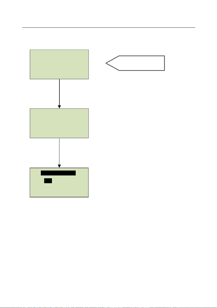
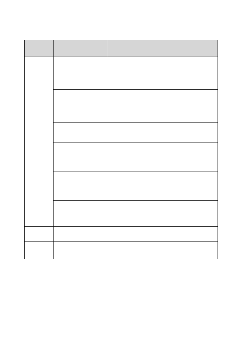
Parameters used to store relevant data set by air compressor manufacturers. To view manufacturer
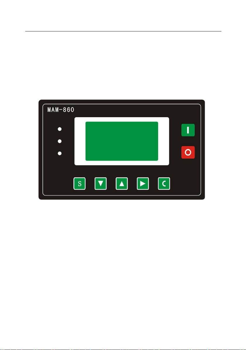
parameters, the manufacturer password must be verified. In the first-level menu, press or key to
move the black scroll bar to the "Manufacturer Parameters" menu, and then press key to enter the
menu below:
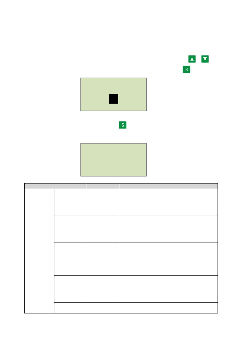
After entering the correct manufacturer password and pressing key, user can enter the manufacturer
parameter interface as shown below:
Parameter Item
Initial Value
Function
System
Parameters
Air End 1
Current
Maximum
allowable
motor
overload
current / 1.2
After delay start of Air End 1, the machine will
present a delay shutdown according to overload
characteristics when the motor current is more
than 1.2 times of the set value.
Air End 2
Current
Maximum
allowable
motor
overload
current / 1.2
After delay start of Air End 2, the machine will
present a delay shutdown according to overload
characteristics when the motor current is more
than 1.2 times of the set value.
Temperature
1
Warning
105℃When Air End 1 temperature is higher than this
set temperature, a warning will be given.
Temperature
1
Shutdown
110℃When Air End 1 temperature is higher than this
set temperature, fault shutdown will be reported.
Shutdown
Pressure
1.00MPa
When the air supply pressure is higher than the
set pressure, fault shutdown will be reported.
Maximum
Unload
Pressure
0.80MPa
Maximum allowable unloading pressure limited
by manufacture on user settings. Unloading
pressure is less than or equal to this set value.
Air End 1
Time
000000 hrs Modify the total running time of Air End 1.
System Parameters
Maintenance Parameter Reset
Maximum Operating Time Preset
Enter Password
****

9
6. List of Manufacturer Parameters
Parameter Item Initial
Value Function
System
Parameters
Air End 2
Time 000000 hrs Modify the total running time of Air End 2.
Fault History
Reset 0000 Enter "8888" and confirm it to clear the fault
history.
Temperature
2
Warning
105℃When Air End 2 temperature is higher than this set
temperature, a warning will be given.
Temperature
2
Shutdown
110℃When Air End 2 temperature is higher than this set
temperature, fault shutdown will be reported.
Date 9999-99-99 Record the manufacture date of air compressor.
Manufacture
Number 99999999
Manufacture number of equipment entered by
manufacturer.
Phase
Sequence
Protection
Disable /
Enable Used to disable or enable the phase sequence
protection.
Frequency
Selection 50Hz/60Hz
Select the working power frequency of air
compressor. If set incorrectly, there will be a
deviation in detected current value.
Connection
Method Advanced /
Compatible Alternate
High Voltage 0000V
When the controller detects that the voltage is
higher than the set value, the machine will shut
down for protection and a higher voltage is
reported. When set to 0000, the high-voltage
function is invalid.
Low Voltage 0000V
When the controller detects that the voltage is
lower than the set value, the machine will shut
down for protection and a lower voltage is
reported. When set to 0000, the low-voltage
function is invalid.
Low
Temperature
Protection -0005℃
When the controller detects that the exhaust
temperature is lower than this value, it shows the
temperature is too low, and the air compressor is
not allowed to start.
Time Limit 0000 hrs
When the air compressor has run for a time greater
than the set time, it will shut down with a report of
"use error"; when set to 0000, the time limit
function is invalid.

10
6. List of Manufacturer Parameters
Parameter Item
Initial
Value
Function
System
Parameters
Warning
Shutdown 0010
hrs
When the controller detects that the use time of oil
filter, oil separator, air filter, lubricating oil, lubricating
grease, and belt exceeds their maximum use time, the
machine will shut down with a report of "too long
warning" after the set time is added.
Communicati
on Preset On/Off
When set to On, the controller allows the host
computer to set parameters according to MODBUS
protocol; when set to Off, the controller does not allow
the host computer to set parameters according to
MODBUS protocol. To modify the parameter through
the host computer, the air compressor needs to be in
stopped state.
Parameter 1 0000
After entering the manufacturer parameter interface,
user can set this value and save it, and view all
manufacturer parameters and modify some of them
next time by entering the set value.
Current
Unbalancedn
ess 0010
When (maximum phase current/minimum phase
current)>= 〔1+(set value/10) 〕
, the unbalance
protection works and the machine shuts down.
When the value is set to ≥15, the unbalance protection
does not work.
Open-phase
Protection 000.0 s
When the open-phase protection time is set to ≥20
seconds, the open-phase protection does not work. If
the unbalance protection works, an unbalance
protection action will occur.
Maintenanc
e Parameter
Reset
Oil Filter
0000
hrs
Total use time of oil filter. Reset it when a new oil
filter is used.
Oil Separator
0000
hrs
Total use time of oil separator. Reset it when a new oil
separator is used.
Air Filter
0000
hrs
Total use time of air filter. Reset it when a new air
filter is used.
Lubricating
Oil
0000
hrs
Total use time of lubricating oil. Reset it when new
lubricating oil is used.
Maximum
Use Time
Preset
Oil Filter 9999
hrs
When the total use time of oil filter exceeds the set
value, a warning will be given; when it is set to "0000",
the warning for use time of oil filter will not work.
Oil Separator 9999
hrs
When the total use time of oil separator exceeds the set
value, a warning will be given;
when it is set to "0000", the warning for use time of oil
separator will not work.
Air Filter 9999
hrs
When the total use time of air filter exceeds the set
value, a warning will be given;
when it is set to "0000", the warning for use time of air
filter will not work.
Lubricating
Oil 9999
hrs
When the total use time of lubricating oil exceeds the
set value, a warning will be given; when it is set to
"0000", the warning for use time of lubricating oil will
not work.

11
7. Adjustment Parameters
Ⅶ. Adjustment Parameters
Adjustment parameters are used to set relevant data of the controller and are not allowed to be viewed and
modified by users who are not authorized by the manufacturer. Users need to verify the manufacturer
password before viewing the adjustment parameters. The modification of the adjustment parameters is the
same as that of user parameters.
Parameter Item
Initial
Value
Function
Air End
1-A
Standard
Current 0000
Used to calibrate Air End 1;
For phase A current, enter the standard current value.
The controller will calculate the current coefficient
based on the division of user input value by current
value currently detected and save it. The standard
current value is not saved and only used to calculate the
coefficient.
Coefficient 1.000 When calibrating the current, enter the coefficient.
Current value displayed on the controller = sampling
value × coefficient
Present
Current ***.*A Display the value of current which is sampled and
calibrated by the controller. This value is a real-time
value and cannot be set.
Air End
1-B
Standard
Current 0000
Used to calibrate Air End 1;
For phase B current, enter the standard current value.
The controller will calculate the current coefficient
based on the division of user input value by current
value currently detected and save it. The standard
current value is not saved and only used to calculate the
coefficient.
Coefficient 1.000 When calibrating the current, enter the coefficient.
Current value displayed on the controller = sampling
value × coefficient
Present
Current ***.*A Display the value of current which is sampled and
calibrated by the controller. This value is a real-time
value and cannot be set.
Air End
1-C
Standard
Current 0000
Used to calibrate Air End 1;
For phase C current, enter the standard current value.
The controller will calculate the current coefficient
based on the division of user input value by current
value currently detected and save it. The standard
current value is not saved and only used to calculate the
coefficient.
Coefficient 1.000 When calibrating the current, enter the coefficient.
Current value displayed on the controller = sampling
value × coefficient
Present
Current ***.*A Display the value of current which is sampled and
calibrated by the controller. This value is a real-time
value and cannot be set.

12
7. Adjustment Parameters
Parameter Item Initial
Value Function
Air End
2-A
Standard
Current 0000
Used to calibrate Air End 2;
For phase A current, enter the standard current value. The
controller will calculate the current coefficient based on
the division of user input value by current value currently
detected and save it. The standard current value is not
saved and only used to calculate the coefficient.
Coefficient 1.000
When calibrating the current, enter the coefficient.
Current value displayed on the controller = sampling
value × coefficient
Present
Current ***.*A
Display the value of current which is sampled and
calibrated by the controller. This value is a real-time
value and cannot be set.
Air End
2-B
Standard
Current 0000
Used to calibrate Air End 2;
For phase B current, enter the standard current value. The
controller will calculate the current coefficient based on
the division of user input value by current value currently
detected and save it. The standard current value is not
saved and only used to calculate the coefficient.
Coefficient 1.000
When calibrating the current, enter the coefficient.
Current value displayed on the controller = sampling
value × coefficient
Present
Current ***.*A
Display the value of current which is sampled and
calibrated by the controller. This value is a real-time
value and cannot be set.
Air End
2-C
Standard
Current 0000
Used to calibrate Air End 2;
For phase C current, enter the standard current value. The
controller will calculate the current coefficient based on
the division of user input value by current value currently
detected and save it. The standard current value is not
saved and only used to calculate the coefficient.
Coefficient 1.000
When calibrating the current, enter the coefficient.
Current value displayed on the controller = sampling
value × coefficient
Present
Current ***.*A
Display the value of current which is sampled and
calibrated by the controller. This value is a real-time
value and cannot be set.
Standard Temperature 0000℃
When calibrating the exhaust temperature, enter the
standard temperature value. The controller will calculate
the temperature coefficient based on the division of user
input value by exhaust temperature currently detected and
save it. The standard temperature value is not saved and
only used to calculate the coefficient.

13
7. Adjustment Parameters
Parameter
Item Initial Value Function
Coefficient 1.000 When calibrating the temperature, enter the coefficient.
Temperature value displayed on the controller = (sampled
temperature value - zero) × coefficient
Zero 0000℃Compensate for the zero deviation of hardware.
Present
Temperature 2 0000℃Display the value of temperature which is sampled and
calibrated by the controller. This value is a real-time
value and cannot be set.
Standard
pressure 00.00MPa
When calibrating the exhaust pressure, enter the standard
pressure value. The controller will calculate the pressure
coefficient based on the division of user input value by air
supply pressure currently detected and save it. The
standard pressure value is not saved and only used to
calculate the coefficient.
Coefficient 1.000
When calibrating the pressure, enter the coefficient.
Pressure value displayed on the controller = sampled
pressure value × coefficient
Zero 00.00MPa When the air supply pressure is less than the set value, it
will be displayed as 0.00MPa.
Present Pressure 00.00MPa
Display the value of pressure which is sampled and
calibrated by the controller. This value is a real-time
value and cannot be set.
Standard voltage 0000V
When calibrating the voltage, enter the standard voltage
value. The controller will calculate the voltage coefficient
based on the division of user input value by voltage value
currently detected and save it. The standard voltage value
is not saved and only used to calculate the coefficient.
Coefficient 1.000
When calibrating the voltage, enter the coefficient.
Voltage value displayed on the controller = (sampled
voltage value - zero) × coefficient
Present Voltage 0000V
Display the value of voltage which is sampled and
calibrated by the controller. This value is a real-time
value and cannot be set.
CURR MODE DEBUG/ WORK
Set the update rate of current display; data is updated fast
in DEBUG mode; data is updated slowly in WORK
mode.
LED NUM 3LED It is set to 3LED.

14
8. Operation Authority and Password Management
Ⅷ. Operation Authority and Password Management
The controller provides multiple password and authority management. Different levels of operation
authority are provided based on different levels of password as follows:
Password
Type Factory
Settings Password Permissions
User Password ----It is allowed to modify all user parameters.
Factory Sales
Password ----It is allowed to modify all user parameters, user passwords,
some factory parameters, and factory sales passwords.
Factory
Password ----It is allowed to modify all user parameters, user passwords,
some factory parameters, factory sales passwords and related
current settings in adjustment parameters.
Factory Super
Password ----
Users can modify the factory parameters of "Run Time",
"Phase Sequence Protection", "Frequency Selection" and "Time
Limit" after entering the factory parameter interface and
verifying the super password again.

Copyright©Huayuan Precision Machine (Shenzhen) Co., Ltd.
The information in this manual is subject to change without notice.
202006(V1.0)
HUAYUAN PRECISION MACHINE (SHENZHEN)CO.,LTD
WeChat
Official
Account
Official
website
Address: No. 5, Hongkan Road, Yanchuan Community,
Yanluo Street, Baoan District, Shenzhen Zip code: 518000
Email:marketing@huayuan-mach.com
Paste dealer information here
24-Hour Hotline
400-0808-650
Table of contents
Popular Controllers manuals by other brands

Motrona
Motrona MM 640 operating instructions

Aerotech
Aerotech UNIDEX 500 Operation & technical manual

Mitsubishi Electric
Mitsubishi Electric CR750-D Series instruction manual

iNels
iNels GSB3-40 manual

TAOS
TAOS TSL2571 EVM2 Kit quick start guide

Gardner Denver
Gardner Denver AUTO SENTRY-ES+ Operating and service manual

Generac Power Systems
Generac Power Systems PowerManager PM-PC manual

erc
erc EASY-ROTOR-CONTROL M instructions

ICM Controls
ICM Controls ICM271 Installation, operation & application guide

LAE
LAE AC1-2W Series Instructions for use

PRIZM
PRIZM Petit Crouto PRIZM v4 user manual

SmartHardware
SmartHardware STR1000008X manual