Stealth Products mo-Vis User manual

Multi Switch
Owner's Manual for the mo-Vis Multi Switch

Customer Satisfaction 1.0
i
Stealth Products strives for 100% customer satisfaction. Your complete satisfaction is important.
Please contact us with feedback or to suggest changes that may help us improve the quality and
usability of our products.
You may reach us at:
Stealth Products
104 John Kelly Drive, Burnet, TX 78611
Phone: (512) 715-9995 Toll Free (800) 965-9229
Fax: (512) 715-9954 Toll Free (800) 806-1225
MDSS GmbH
Schigraben 41
30175 Hannover, Germany
General
Read and understand all instructions prior to the use of this product. Failure to adhere to instructions
and warnings in this document may result in property damage, injury, or death. Product misuse due
to failure to adhere to the following instructions will void the warranty.
Immediately discontinue use if any function is compromised, if parts are missing or loose, or if any
component shows signs of excessive wear. Consult your supplier for repairs, adjustments, or
replacements.

Important Information 2.0
ii
Important Information
All persons responsible for tting, adjustment, and daily use of the devices discussed in these
instructions must be familiar with and understand all safety aspects of the devices mentioned. In order
for our products to be used successfully, you must:
• read and understand all instructions and warnings;
• maintain our products according to our instructions on care and maintenance; and,
• ensure devices are installed and adjusted by a trained technician.
Supplier Reference
Supplier:
Telephone:
Address:
Purchase Date:
Model:

Introduction 3.0
iii
The installation instructions will guide you through the options and possibilities with the product.
Instructions are written with the expressed intent of use with standard congurations. They also
contain important safety and maintenance information, as well as describe possible problems that can
arise during use. For further assistance or more advanced applications, contact your supplier or
Stealth Products at (512) 715-9995 or toll free at (800) 965-9229.
Always keep the operating instructions in a safe place so they may be referenced as necessary.
All information, pictures, illustrations, and specications are based on the product information that
was available at the time of printing. Pictures and illustrations shown in these instructions are
representative examples and are not intended to be exact depictions of the various parts of the
product.
Ordering Documentation
You can download additional copies of this user manual by accessing the Stealth Products website
(https://stlpro.site/stealth-docs) and searching "mo-Vis Multi Switch Owners Manual" in the search bar
at the top of the page.

Warranty 4.0
iv
Our products are designed, manufactured, and produced to the highest of standards. If any defect in
material or workmanship is found, Stealth Products, LLC will repair or replace the product at our
discretion. Any implied warranty, including the implied warranties of merchantability and tness for a
particular purpose, shall not extend beyond the duration of this warranty. Stealth Products, LLC does
not warrant damage due to, but not limited to:
• misuse, abuse, or misapplication of products; and/or
• modication of product without written approval from Stealth Products, LLC.
Any lack or alteration of serial number, where applicable, will automatically void this warranty.
Stealth Products, LLC is liable for replacement parts only. Stealth Products, LLC is not liable for any
incurred labor costs.
No person is authorized to alter, extend, or waive the warranties of Stealth Products, LLC.
Covers/Soft Goods: 2 years
Hardware: 5 years
Electronics: 3 years
In Case of Product Failure
In the event of product failure covered by our warranty, please follow the procedure outlined below:
1. Call Stealth Products at (512) 715-9995 or toll free at (800) 965-9229.
2. Request a Return Authorization form (RA) from the Returns Department and follow documentation
instructions.

Table of Contents 5.0
v
1.0 Customer Satisfaction ................................................................................................................i
2.0 Important Information ............................................................................................................ ii
3.0 Introduction .................................................................................................................................iii
4.0 Warranty.........................................................................................................................................iv
5.0 Table of Contents........................................................................................................................ v
6.0 Warning Labels ...........................................................................................................................vi
6.1 Warning Labels ...................................................................................................................vi
6.2 Limited Liability...................................................................................................................vi
6.3 Testing....................................................................................................................................vi
7.0 Design and Function ................................................................................................................. 1
7.1 Intended Use ....................................................................................................................... 1
7.2 Features ................................................................................................................................. 1
8.0 Parts and Accessories ...........................................................................................................2-3
8.1 Multi Switch Package........................................................................................................ 2
8.2 Mounting the Multi Switch ............................................................................................ 3
9.0 Technical Data .......................................................................................................................4-13
9.1 USB Power Supply ............................................................................................................. 4
9.2 Input........................................................................................................................................ 4
9.3 Output.................................................................................................................................... 4
9.4 mo-Vis Congurator Software...................................................................................... 5
9.5 Output Operation Mode Selection............................................................................. 5
9.6 Troubleshooting ...............................................................................................................10
9.7 Technical Dimensions and Specications...............................................................13
10.0 Installation Instructions......................................................................................................14
10.1 Preparations ....................................................................................................................14
10.2 Tools ...................................................................................................................................14
10.3 Installation Plan..............................................................................................................14
10.4 Installing the Multi Switch .........................................................................................14
11.0 First Time Use ..........................................................................................................................15
12.0 Maintenance.............................................................................................................................16
12.1 Maintenance....................................................................................................................16
12.2 Cleaning ............................................................................................................................16
Warning Labels 6.0
vi
Warning Labels 6.1
Warnings are included for the safety of the user, client, operator, and property. Please read and
understand what the signal words DANGER, WARNING, CAUTION, NOTICE, and SAFETY mean, and
how they could aect the user, those around the user, and property.
Limited Liability 6.2
Stealth Products, LLC accepts no liability for personal injury or damage to property that may arise
from the failure of the user or other persons to follow the recommendations, warnings, and
instructions in this manual.
Stealth Products LLC does not hold responsibility for nal integration of nal assembly of product to
end user.
Stealth Products, LLC is not liable for user death or injury.
Testing 6.3
Initial setup and driving should be done in an open area free of obstacles until the user is fully capable
of driving safely.
CAUTION Identies a potential situation which, if not avoided, may result in minor to
moderate injury and property damage.
WARNING Identies a potential situation which, if not avoided, may result in severe
injury,death, and property damage.
DANGER Identies an imminent situation which, if not avoided, may result in severe
injury,death, and property damage.
NOTICE Identies important information not related to injury, but possible property
damage.
SAFETY Indicates steps or instructions for safe practices, reminders of safe procedures,
or important safety equipment that may be necessary.

Design and Function 7.0
1
Intended Use 7.1
The Multi Switch is intended to control up to four devices/technical aids with one input device (mechanical
or proximity switch). The mechanical switch is only intended to support auxiliary wheelchair function. The
Multi Switch oers the user greater freedom of operation and increased function control. The switch is USB
powered and contains its own control electronics.
The Multi Switch is also available as part of a package which includes proximity sensors. The sensors can be
used as input devices and require no force to activate. The addition of mo-Vis proximity sensors increases the
level of autonomy aorded the chair user.
Multi Switch Features 7.2
mo-Vis' Multi Switch features:
• one 3.5mm stereo input jack, allowing a mechanical switch or proximity sensor input connection;
• two 3.5mm stereo output jacks, allowing up to four separate outputs (with splitter cables, sold
separately);
• a LED for each output channel, indicating status and activity of the channel;
• clear, audible feedback;
• fully adjustable input and output parameters via conguration software; and,
• multiple mode settings.
Proximity Sensor Features 7.3
mo-Vis proximity sensors, sold separately from and compatible only with the Multi Switch, feature:
• two size options:
• 12mm for installations with limited space; and,
• 24mm for installations requiring increased sensitivity.
• sensitivity adjustment via congurator software; and,
• easy calibration and conguration.
CAUTION
Moisture (e.g., rain) is a conductive substance. While a negligible
amount of liquid may not interfere with device operation, a coating
of moisture can cause the sensors to constantly read as activated.
Parts and Accessories 8.0
2
Multi Switch Package 8.1
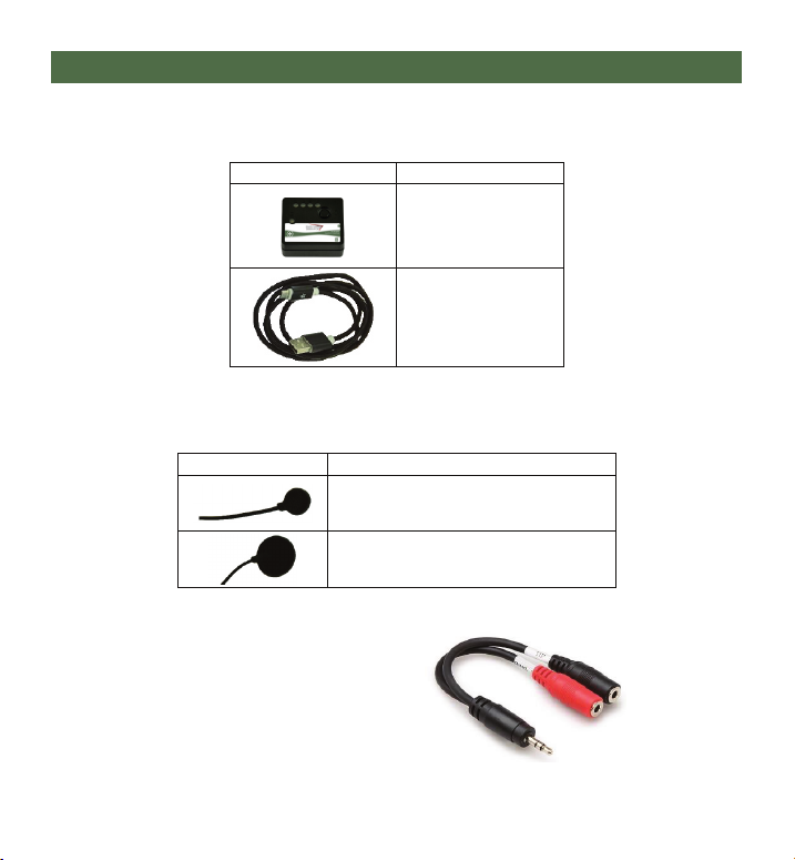
Included in the Multi Switch package:
For proximity sensor input, only mo-Vis proximity sensors (sold separately) are compatible with the
Multi Switch. These are:
Optional: Splitter Cable
The 3.5mm stereo to 3.5mm
mono splitter (sold separately) is
required to convert a single
output to a dual output.
Product Description
Multi Switch Proximity Sensor (12mm)
Multi Switch Proximity Sensor (24mm)
Product Description
Multi Switch Unit
USB to Micro USB
Connector Cable

Parts and Accessories 8.0
3
Mounting the Multi Switch 8.2
Its exceedingly small size grants the Multi Switch nearly unlimited mounting options.
The use of hook-and-loop adhesive patches is recommended when mounting the switch.
(Note: Hook-and-loop adhesive patches are not included with the Multi-Switch.)
CAUTION Keep devices that emit radio frequencies (e.g., mobile phones)
at least 30cm (12") from the sensor and its connecting cable.
NOTICE Only install this product on wheelchairs onto which
the manufacturer allows the installation of third-party parts.
CAUTION
In case high sensitivities are utilized for sensors (70%),
ensure the sensor is rmly xed and its cables routed in a way
that avoids kinks or obstructions. Moving the sensor or its cables
can inuence its sensitivity, possibly producing false activations.
NOTICE
Ensure the user has unobstructed visual contact with the LEDs
on the front of the Multi Switch, in order to check its status.
Although every activation is able to trigger an auditory signal, it is not
recommended to rely on this alone for activation conrmation.
CAUTION
The Multi Switch is not waterproof. While a few drops of water
will not likely cause problems, the device should be mounted
in such a way as to ensure that water cannot enter the device.
NOTICE
The electronics of the Multi Switch can be aected by external electromagnetic
elds (e.g., elds generated by mobile telephones). The electronics themselves can
also emit electromagnetic elds that can aect electronics in their immediate
surroundings (e.g., certain electronic alarm systems). The limit values for
Electromagnetic Compatibility (EMC) with respect to this type of device are set in
the harmonized standards for the EU in the Medical Device Directive, No. 93/42/
EEC. The Multi Switch unit and its proximity sensors comply with these values.

Technical Data 9.0
4
USB Power Supply 9.1
The Multi Switch is powered by means of a micro USB connection. When the device is plugged into a USB
power source, such as a USB charger, a laptop, or a power bank, the device will be powered and ready to use.
The Switch requires a minimal amount of energy. Some power sources are not designed to deliver minimal
current over long durations. Accordingly, proper device functionality is not guaranteed with any power
source.
Contact your dealer or mo-Vis for more information and for assistance with choosing the correct power source
for the Multi Switch.
Output 9.3
Input 9.2
The Multi Switch has a single 3.5mm
input jack, which is compatible with two
types of switches:
The Multi Switch is equipped with four green LEDs
on the device's face that indicate its output. They
indicate the channel currently selected, and shifts to
select the desired channel.
A separate green LED on the face of the device
indicates the device status.
When used with a splitter cable (sold separately), the
Multi Switch is capable of four output functions.
Switch Type: Input:
Mechanical Use a switch equipped
with a 3.5mm mono jack
Proximity Use mo-Vis
proximity sensors
Status: LED Action:
Active - Short blink, long pause
Fault - Series of blinks, long pause
(error, see troubleshooting)
Outputs: Location:
1,2 Green mono jack
3,4 Yellow mono jack
CAUTION
A ground loop can be introduced into the connection if the USB port and the input jack
are plugged into circuits powered by the same battery. This can cause a grounded current to
ow from one circuit to another through the Multi Switch, and if the current is too high,
the Multi Switch can be over-stressed and may not function properly, leading to permanent
damage to the device. One way to avoid introducing a ground loop to the connection is to
connect the device to an isolated USB power supply.

Technical Data 9.0
5
mo-Vis Congurator Software 9.4
Output Operation Mode Selection 9.5
The user can change output operation modes on the Multi Switch. The 'Mode Select' feature is used to
select one of the active outputs.
(Note: If only one active output is available for selection, 'Mode Select' will automatically control Input 1.)
NOTICE When power is removed from the Multi Switch,
all its outputs will return to their open state.
Sensitivity
24mm Sensor
Distance
(in mm)
12mm Sensor
Distance
(in mm)
100% 10.00 3.00
90% 8.50 2.00
80% 7.00 1.25
70% 5.00 0.50
60% 3.00 0.20
50% 2.00 0.10
40% 1.50 0.05
30% 1.00 <0.05
20% 0.50 <0.05
10% 0.25 <0.05
5% 0.05 <0.05
Proximity Sensor Information
The mo-Vis proximity sensor is based on the
principle of capacitive sensing. It is capable of
measuring objects (e.g., a nger or metal stick)
that approach the sensor. The larger the surface
of the sensor, the more sensitive it will be (the
24mm being the most sensitive). The sensor is
most sensitive at its front in the center. Its sides
are slightly sensitive, and the underside is immune.
mo-Vis provides a congurator software on its website (www.mo-vis.com) or Stealth Products website
(https://www.stealthproducts.com/p/52/) that enables users to adjust and customize nearly every aspect of
the Multi Switch's operation. For details on how to install and use the software, the user is advised to consult
the congurator software manual, included in the software download.
- Windows 7, 8, or 10 is required to run the software.
With Dealer-level software access, you will be able to congure a number of parameters for the Multi Switch.
- Dealer-level access requires a password.
To obtain a password for the software, call Stealth Products at (512) 715-9995 or toll-free at (800) 965-9229
and speak to a customer service representative.

Technical Data 9.0
6
Click Mode:
To generate one or more short clicks, quickly open and close (activate and deactivate) the
input. (The period between the clicks has to be shorter than the 'Action Delay' time.)
After the clicks are input,
- The output will be closed for a set time (depending on the output's 'Close Time' setting), or
- the selected output will remain locked until released (depending on the output's 'Lock' setting).
Start Scan:
A quick click (input activation) will begin a scan of available active outputs.
- A number of beeps corresponding to the number of available active outputs will be generated, and
- a corresponding selection LED will be activated.
When the desired output is indicated, click (activate) the input again to select and activate
the output. The output will react.
- The output will remain closed as long as the input is closed, or
- the output will remain locked until it is manually deselected (depending on the output's 'Lock'
setting).
The scanning of the outputs is done at an interval of 'Select/Scan Time'.
(Note: If too much time elapses without selecting and activating an output, the selection process will stop and no
output will be activated. This is a built-in feature designed to allow any unwanted input to be canceled.
Mode Select
Hold and Scan:
Activating and holding the input will begin a scan of available active outputs.
- A number of beeps corresponding to the selected output will be generated, and
- a corresponding selection LED will be activated.
When the desired output is indicated, release the input to select and activate the output.
The output will react.

Technical Data 9.0
7
Select Timed Click:
Selection in this mode is dependent on duration and number of clicks.
- For outputs 1 to 3, keep the input closed to scan the outputs. A number of beeps and
corresponding LED will be activated.
- Output 1: Short press (<Select/Scan Time)
- Output 2: Medium Press (>Select/Scan Time)
- Output 3: Long Press (>2x Select/Scan Time)
- For output 4, double click (within the Select/Scan Time)
When the desired output is indicated, release the input again to select and activate the
output.
-The output will remain closed for a set time (depending on the output's 'Close Time' settings), or
-the output will remain locked until it is manually deselected (depending on the output's 'Lock'
setting).
(Note: If too much time elapsed without selecting and activating an output, the selection process will stop and no
output will be activated. This is a built-in feature designed to allow any unwanted input to be canceled.
Continuous Scan:
In this mode the active outputs are scanned continuously.
When the desired output is indicated, close the input to select and activate the output.
- The output will remain closed as long as the input is closed, or
- The output is locked until released (depending on the output's 'Lock' setting)
- The output will remain closed as long as the input is closed, or
- the output will remain locked until it is manually deselected (depending on the output's 'Lock'
setting).
(Note: If too much time elapses without selecting and activating an output, the selection process will stop and no
output will be activated. This is a built-in feature designed to allow any unwanted input to be canceled.)

Technical Data 9.0
8
'Lock Mode' is designed to allow the user to control and activate a device for longer periods of time (e.g.,
with a communication or environmental device).
When 'Lock Mode' is set to active, it will be locked in the selected output. To unlock this mode, the input
needs to be closed (activated) and held shorter/longer than the 'Quit Time', depending on the setting.
Lock Mode options are:
No (default): normal operation, after the input was operated, return to selection mode.
Timed Closed: the output will be locked in the selected output mode. To escape this mode (i.e. to break the
lock), close the input continuously for longer than the 'Quit Time'. When working in this mode, the output
will be closed when the input is closed. This means that when you break the lock, your output will react as
well.
Timed Open: The output will be locked in the selected output mode. To break the lock, close the input
continuously for a time longer than the 'Quit Time'. When working in this mode, the output will be closed
when the input is released.
Nudge: The output will be locked in the selected output mode. To break the lock, close the input for a time
shorter than the 'Quit TIme'. The output will be closed only if you hold longer than the 'Quit Time'.
Lock Mode
Momentary/Timed:
- The output will remain closed as long as the input is closed, or
- the output will be closed for a set time.
Switched:
- the output will toggle between open and closed. This is useful to switch something on continuously.
Momentary/Timed or Switch Mode

Technical Data 9.0
9
Auto:
The system will make automatic adjustments over time. (Note: This is only a usable setting for situations in
which the user of the device is able to maintain a distance of at least 30mm (12") from the sensor when
he/she is not operating it.)
Manual:
Have the user determine at what point he/she would like the input to be considered open/activated. When
that position is reached, press the push button on the front of the switch box, and the system will store that
position as the open reference.
When the calibration is successful, a continuous beep will sound. If the calibration has been unsuccessful
(i.e., if 'Calibration Mode' is set to Auto or a mechanical switch is connected), a series of short beeps will
sound.
Manual calibration mode is necessary when the activating part of the user's body remains constantly closer
than 30mm (12") to the sensor. If this is the case, manual calibration should be undergone regularly.
Calibration Mode
WARNING 'Calibration Mode' can only be used to calibrate proximity sensors.

Technical Data 9.0
10
Parameter Setting 9.7
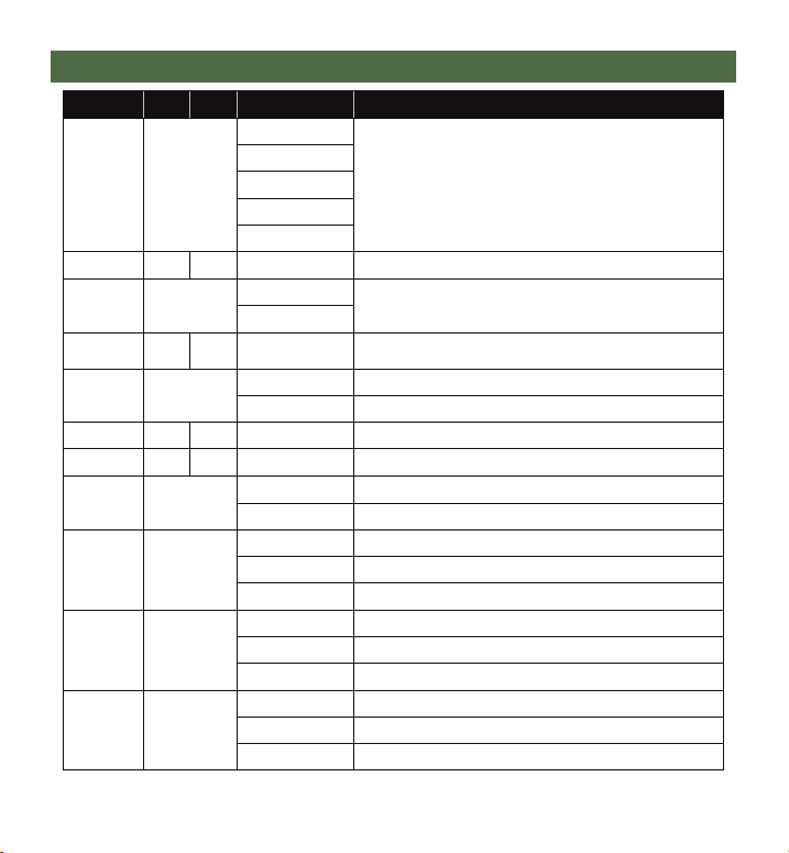
Flash Codes:
When a fault occurs, the output LED will begin to ash. There will be a long delay followed by a
number of ashes with a short delay. Count the number of ashes, then nd the corresponding
information in the table below.
Error Codes:
The Multi Switch maintains a fault log with fault counters. Each time a specic fault occurs, its
counter will be incremented by one. The fault log can be accessed by the congurator (Dealer-level
prole access). This user can clear one or all of the errors from the fault log.
In the case of error codes, please contact mo-Vis to learn about the required actions.
Should a problem persist after corrective action, please contact your local dealer or mo-Vis service
engineer.
Flash
Count: Fault Reason Required Action:
1- -
2- -
3Power Supply
(voltage under or over) Check power connections
4Sensor Replace printed circuit board (PCB)
5- -
6ADC
(internal analog-to-digital converter) Replace PCB
7Failure of test ag or diagnostic - Redo tests
- Replace PCB
8CPU fault Replace PCB
9Scheduler fault - Update Software
- Replace PCB
10 Coding error
Troubleshooting 9.6
Technical Data 9.0
11
Parameter: Min.: Max.: Default/Options: Description:
Select Mode -
Select by Click
See 9.5 Output Operation Mode Selection
(Mode Select, p. 6)
Start Scan
Hold and Scan
Select Timed Click
Continuous Scan
Active
Outputs 1 4 1 The number of outputs used
(If set to '1', the switch will never enter Select mode)
Calibration
Method
(Proximity
mode only)
-
Auto See 9.5 Output Operation Mode Selection
(Calibration Mode, p. 9)
Manual
Sensitivity
(Proximity
mode only) 10 100 50 Proximity switch sensitivity (higher value = more sensitivity)
(Reduce this value in case of false positives)
Output
Sequence -
Tip - Tip Select sequence: Green Tip, Yellow Tip, Green Ring, Yellow Ring
Tip - Ring Select sequence: Green Tip, Green Ring, Yellow Tip, Yellow Ring
Action Delay 10 2500 50 (Time in ms)
Select/Scan
Time 100 5000 1000 (Time in ms) This is also the scan time.
Input Beep -
None No sound (default)
Short Short beep
Select Beep -
None No sound
Medium Normal beep (default)
Long Long beep
Output Beep -
None No sound
Short Short beep (default)
Medium Normal beep
Quit Beep -
None No sound
Medium Normal beep
Long Long beep (default)

Technical Data 9.0
12
Parameter: Min.: Max.: Default/Options: Description:
Mode -
Momentary/Timed Output will remain closed at least as long as
the Close Time, or longer.
Switched Output will toggle between open and closed
Close Time 20 60000 200 Time (in ms) output will remain closed
(timed output only)
Lock - -
No
See 9.5 Output Operation Mode Selection
(Lock Mode, p. 8)
Timed Closed
Timed Open
Nudge
Quit Time 200 60000 5000 Time (in ms) needed to close the input to unlock parameter
('Lock' must be set to 'Yes')
OUTPUT SETTINGS:
Technical Data 9.0
13
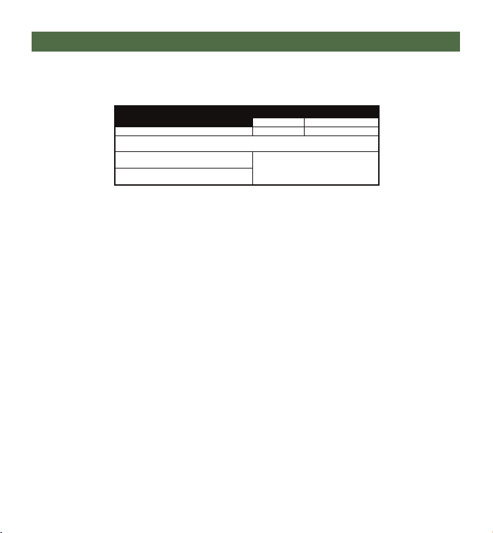
Product Description and Codes:
Multi Switch Unit Dimensions:
- 36mm x 40mm x 17mm (Height x Width x Depth)
- 1.42 in. x 1.57 in. x 0.67 in. (Height x Width x Depth)
Voltage Supply:
- MicroUSB = 5V
Power Consumption:
- 14 mA
Input:
- Mechanical switch (Closed = 200kOhm max.; Open = 150kOhm min.)
- mo-Vis proximity sensor (12mm or 24mm)
Output:
- Max. = 60V (75mA)
Sensor Cable Length:
- 120cm (3.93 ft.)
Relevant Testing:
- EN12182
Technical Dimensions and Specications 9.7
Description Product Code
mo-Vis Stealth Products
Multi Switch Unit P014-40 IDM-MS
Multi Switch Proximity Set
P014-20 IDM-MS-SS
(sold as a set)
P014-23
This manual suits for next models
5
Table of contents
Other Stealth Products Switch manuals


