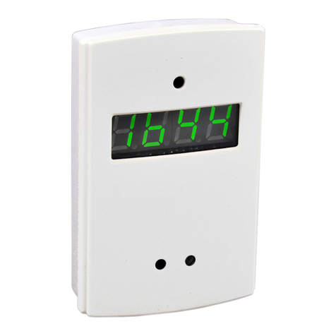
Stealth Products IC12F-1 User manual

Alternative
Drive Controls
Fiber Optics
Owner’s Manual - Maintenance Guide
IC12F-1, IC24F-1, IDH503, IDHF510-1
Fiber Optic Switches

I
Table of Contents
Customer Satisfaction .............................................................i
Important Information......................................................ii-iii
Warranty ...........................................................................................ii
Supplier Reference........................................................................ii
Warning Labels..............................................................................iii
Limited Liability.............................................................................iii
Testing ..............................................................................................iii
Design and Function...............................................................1
Intended Use.................................................................................. 1
Specications................................................................................. 1
Installation Instructions .....................................................2-5
Installation Notes......................................................................... 2
Mounting the Amplier Box .................................................... 3
Power Supply ................................................................................. 4
Fiber Optic Cables........................................................................ 4
Locking the Cable in the Amplier........................................ 5
Programming Instructions.....................................................6
Layout............................................................................................... 6
Tuning...................................................................................7-8
Tuning............................................................................................... 7
Tuning Errors.................................................................................. 7
Additional Features ..................................................................... 8
First-Time Use..........................................................................9
Dealer Assistance ......................................................................... 9
User Testing.................................................................................... 9
Conditions of Use ........................................................................ 9
Maintenance ......................................................................... 10
Cleaning.........................................................................................10
Maintenance ................................................................................10

i
Customer Satisfaction
Stealth Products is committed to 100% customer satisfaction. Your complete
satisfaction is important to us. Please contact us with feedback or suggestions to
help us improve the quality and usability of our products.
You may reach us at:
Stealth Products, LLC
104 John Kelly Drive
Burnet, TX 78611
Phone: (512) 715-9995 Toll Free: (800) 965-9229
Fax: (512) 715-9954 Toll Free: (800) 806-1225
www.stealthproducts.com
MDSS GmbH
Schigraben 41
30175 Hannover, Germany
General
Read and understand all instructions prior to the use of the product. Failure to
adhere to instructions and warnings in this document may result in property
damage, injury, or death. Product misuse or failure to follow instructions will void
the warranty.
Immediately discontinue use if any function is compromised, if parts are missing
or loose, or if any component shows signs of excessive wear. Consult with your
supplier for repair, adjustment, or replacement.
All persons responsible for tting, adjustment, and daily use of the devices
discussed in the these instructions must be familiar with and understand all safety
aspects of the devices mentioned. In order for our products to be used
successfully, you must read and understand all instructions and warnings, and
maintain our products according to our instructions on care and maintenance.
The installation instructions will guide you through this product’s options and
possibilities.
Instructions are written with the expressed intent of use with standard
congurations. They also contain important safety and maintenance information,
as well as describe possible problems that can arise during use. For further
assistance, or more advanced applications, please contact your supplier or Stealth
Products at (512) 715-9995 or toll free at (800) 965-9229.
Always keep the operating instructions in a safe place so they may be referenced
as necessary.
All information, pictures, illustrations, and specications are based on the product
information that was available at the time of printing. Pictures and illustrations
shown in these instructions are representative examples and are not intended to
be exact depictions of the various parts of the product.

ii
Important Information
Supplier Reference
Supplier:
Telephone:
Address:
Purchase Date:
Model:
Warranty
Our products are designed, manufactured, and produced to the highest of
standards. If any defect in material or workmanship is found, Stealth Products will
repair or replace the product at our discretion. Any implied warranty, including the
implied warranties of merchantability and tness for a particular purpose, shall not
extend beyond the duration of this warranty. Stealth Products does not warrant
damage due to, but not limited to: misuse, abuse, or misapplication of product,
and/or modication of product without written approval from Stealth Products, LLC.
Any alteration or lack of serial number, where applicable, will automatically void all
warranty.
Stealth Products, LLC is liable for replacement parts only. Stealth Products, LLC is
not liable for any incurred labor costs. Stealth Products warrants against failure
due to defective materials or workmanship:
Covers: 2 years
Hardware: 5 years
Electronics: 3 years
In the event of a product failure covered by our warranty, please follow the
procedures outlined below:
Call Stealth Products at (512) 715-9995 or toll free at (800) 965-9229.
Request a Return Authorization (RA) form from the Returns Department and follow
the documentation instructions.
Additional warranty information may be found by visiting the website at https://
stlpro.site/returns-n-warranty. Copies of this manual may be downloaded by
accessing the Stealth website (https://stlpro.site/stealth-docs) and searching “Fiber
Optics Owners Manual” in the search bar at the top of the page.
CAUTION
These products are designed to be tted, applied, and
installed exclusively by a healthcare professional trained for
these purposes. The tting, application, and installation by a
non-qualied individual could result in serious injury.

iii
Important Information
Warning Labels
Warnings are included for the safety of the user, client, operator, and property.
Please read and understand what the signal words DANGER,WARNING,
CAUTION,NOTICE, and SAFETY mean, and how they could aect the user, those
around the user, and property.
Limited Liability
Stealth Products, LLC accepts no liability for personal injury or damage to
property that may arise from the failure of the user or other persons to follow the
recommendations, warnings, and instructions in this manual.
Stealth Products does not hold responsibility for nal integration of nal
assembly of product to end user. Stealth Products is not liable for user death or
injury.
Testing
Initial setup and driving should be done in an open area free of obstacles until
the user is fully capable of driving safely.
CAUTION Identies a potential situation which, if not avoided, may
result in minor to moderate injury and property damage.
WARNING Identies a potential situation which, if not avoided, may
result in severe injury,death, and property damage.
DANGER Identies an imminent situation which, if not avoided, may
result in severe injury,death, and property damage.
NOTICE Identies important information not related to injury,
but possible property damage.
SAFETY
Indicates steps or instructions for safe practices,
reminders of safe procedures, or important safety
equipment that may be necessary.

1
Design and Function
Intended Use
The Fiber Optic is a small sensor that can easily be situated in conned
spaces, individually, or in groups to create an array of switch sensors. It can
be powered by the i-Connect system or the i-Drive interface, does not
conduct electricity, or require physical contact to operate, and can be
connected to virtually any available switch site. The Fiber Optic sensor
utilizes a visible red laser and provides no audible feedback. Simply by
covering the appropriate sensor, the driver can control the PWC. Drivers
can steer the wheelchair by activating the forward or reverse activation
beam in combination with either the right or left activation beam.
Specications
Sensor Size
M3x0.5x2.5mm W
x 2-0.5mm ⌀x 11mm D,
5.5mm W with nuts
Ambient
Temperature
-40°F to 158°F
-40ºC to 70ºC
Weight Approx. 20 Grams Ambient
Humidity
35% to 95%
Relative Humidity
Dierential
Distance
20% max. of sensing
distance
Storage
Temperature
-40°F to 185°F
-40ºC to 85ºC
Sensor Type Diuse-reective Operating
Voltage Range 10V to 30V DC
Sensor Material Nickel-Plated Brass Cable Length 6 ft.

2
Installation Instructions
Installation Notes
▪ To bend the cable, we recommend a bend radius that is at least
6.6mm (.26 in).
▪ Do not bend the edge of the ber units closest to the tip and sensor.
▪ When wiring the cable, do not subject the cable to a tension greater
than 9.8N maximum.
▪ Do not compress or place heavy loads on the bers. The method
shown below may be an eective method to secure the ber to the
chair, while avoiding excessive load (29.4N max.).
▪ The method shown below is an eective way to prevent the ber
from breaking due to vibration.
Fiber Unit
Amplier Unit
✓ ✗
20mm min.
20mm min.
✓✗
Fiber Unit
Nylon Wire Holder
Forming one-turn
loop will reduce
vibration
Tape

3
Installation Instructions
Mounting the Amplier Box
▪ The amplier box should be mounted in a secure location where it
will not be damaged.
▪ Mount the amplier box using the mounting tabs on the edges of
the box or by applying hook and loop material or another suitable
form of removable adhesive.
▪ Although the box can be mounted anywhere, it is preferable to
mount it to the back of the chair or in another location where it is
less likely to be damaged by impact.
▪ Ensure that excess wiring is gathered and securely routed to avoid
entanglement with the user or other equipment.
Hook and Loop
Adhesive
NOTICE Hook and Loop adhesive and screws for mounting
the Amplier Box are not included.

4
Installation Instructions
Power Supply
The i-Connect version of Fiber Optics (IC12F-1 and IC24F-1) will require an
appropriate version of the i-Connect power source. For more information,
see the ICPS user manual (Available at https://stlpro.site/stealth-docs,
search: ICPS)
The i-Drive compatible version (IDH503 & IDHF510-1) will be powered by
the i-Drive.
Fiber Optic Cables
Cutting
1. Insert the ber cable into an appropriate ber cutting hole.
2. Press down on the blade with a single stroke to cut the ber cable.
a. A clean cut is necessary to ensure proper function of the amplier.
Fiber Attachment Adjustment
The attachment of the end of the ber cable must be properly adjusted to
ensure proper function. Repetitive removal of the ber cable from the
amplier may require readjustment of the attachment.
1. Loosen the ber attachment by twisting the top portion only.
a. It is not necessary to remove the top portion; it only needs to be
loose.
2. Slide the ber cable in or out until the ber extends approximately .5mm
(1/64 in.) past the tip.
Approx. 0.5mm
Insertion Direction
Note: Insert the ber in the direction indicated by the arrow.
NOTICE Trimming excess cable may help prevent
accidental damage to the ber optic cable.

5
Installation Instructions
Locking the Cable in the Amplier
1. Open the lock lever by releasing it away from the ber cable receiving
holes.
2. Insert the ber cable into the receiver hole until it bottoms out. Do not
force it past this point.
3. Close the lock lever by ipping it toward the receiver holes.
▪ The ber sensor end of the ber cable must be properly mounted to
ensure proper function. Once the location has been determined, use
the supplied nuts and washers to mount the sensor. The image
below shows an example of the correct mounting.
Note: Do not exceed a clamping force of .78 N·m on the mounting nuts.
Note: Use a properly-sized 3mm wrench to avoid damage to sensitive
parts.
Locked Unlocked
Receiver
holes
Protective Cover
Mounting Plate
Toothed Washers
Nuts
(attachment)

6
Programming Instructions
Layout
• Threshold Level -- Numbers displayed in Green. This indicates the level that
must be achieved to cause a successful activation.
• Incident Light Level -- Numbers displayed in Red. This indicates the level at
which the Fiber Optic is currently sensing a reection, i.e. how far away an
object is from the sensor.
• L/D -- Light On/Dark On
▪ When set to Light On, the beam must be broken (covered) to activate
the signal to the chair. This is most commonly used in situations
when the Fiber Optic is being used to send drive or mode commands
to the chair.
▪ When set to Dark On, the beam must be unbroken (uncovered) to
activate the signal to the chair. This is most commonly used in
situations when the Fiber Optic is being used as an emergency stop
function, such as a ber optic attached to a sip-n-pu straw.
• Tuning -- Tuning is used to precisely set the distance at which the activations
will occur. This will help produce a more precise driving experience.
Note: Refer to the following sections for more information about tuning
and additional settings.
NOTICE All of Stealth's Fiber Optics utilize the same amplier.

7
Tuning
Tuning
Automatic Tuning
Automatic Tuning will capture the capabilities of the end user. This will
automatically assign a threshold level based on light levels during tuning.
1. Press the Tune button once while breaking the beam.
a. The display will read St 1Pnt.
2. Press the Tune button once again with nothing breaking the beam.
a. The display will read St 2Pnt.
3. Setting is complete.
NOTICE Start with auto-tuning then adjust with minute-tuning if
auto-tuning fails or if small adjustments are required.
NOTICE
Steps One and Two may be reversed. The larger
of the two light levels will be used for this setting.
The threshold will be set based on this.
Minute Tuning
Minute Tuning allows you to ne tune the threshold level.
1. Press the '+' or '-' button until you nd the appropriate threshold.
a. '+' will increase the threshold value. The higher the number, the
closer to the emitter you must be to break the beam.
b. '-' will decrease the threshold value. The lower the number, the
farther from the emitter you must be to break the beam.
A higher threshold level typically means that the activation occurs closer to
the sensor as compared to a lower threshold level.
Tuning Errors
Error
Displayed Cause Remedy
nEAr Err Light level between points
1 and 2 are too small.
• Re-tune the system.
• Mount the sensor closer to the surface
that is breaking the beam.
ovEr Err Light level is too high.
• Re-tune the system.
• Increase the tuning level.
• Mount the sensor farther from the surface
that is breaking the beam.
Lo Err Light level is too low.
• Re-tune the system.
• Increase the tuning level.
• Mount the sensor farther from the surface
that is breaking the beam.

8
Tuning
Additional Features
Light On / Dark On
A single press of the L/D button will swap between the Light On and Dark On
modes.
▪ Light On: User must break the beam to activate, much like a normally
open switch.
▪ Dark On: User must break the beam to deactivate, much like a
normally closed switch.
Reset Settings
This feature will return the amplier to factory settings.
1. Press and hold the Tune button. While holding the Tune button, press the
L/D button.
a. Hold for 3 seconds or longer.
2. Select rSt button on the display with the '+' or '-' buttons.
a. Press the Mode button.
3. Select rSt init button on the display with the '+' or '-' buttons.
a. Press the Mode button.
Locking Buttons
This feature will disable all button operation. Loc-on will display when a
button is pressed.
1. Press and hold either the '+' or '-' button and the Mode button at the
same time.
a. Hold for 3 seconds or longer.
Repeat the process to unlock.

9
First Time Use
Dealer Assistance
During rst time use by the client, it is advised that the dealer or service
technician assists and explains the conguration to the customer (the user
and/or the attendant). If needed the dealer can make nal adjustments.
User Testing
It is important that the customer is fully aware of the installation and what/
how the product can be adjusted. Ensure the user can safely operate the
wheelchair and that the ber optics are working properly, and in the
necessary way.
If needed, adjust the ber optics so they function to the user's needs.
Explain to the customer possible problems and how to address them.
Conditions of Use
The proximity ber optics are intended for use as installed by the dealer, in
accordance with the installation instructions in this manual.
▪ The foreseen conditions of use are communicated by the dealer or
service technician to the user and/or attendant during the rst time
use.
▪ If the usage conditions change signicantly, please contact your
dealer or service technician to avoid excessive wear and tear or
unintended damage.
WARNING Check that no cabling is loose and the user can
operate the chair properly with the Fiber Optics attached.

10
Maintenance
Cleaning
Periodically ensure the ber optic sensor is free and clear of foreign debris.
To clean:
▪ Gently wipe o with a dry cloth, or blow o with compressed air.
▪ Do not use thinners or other organic solvents.
▪ If necessary, tighten screws or reapply the adhesive used to secure
the box.
▪ Check that all connections are tight.
Maintenance
▪ Check the ber optic sensor(s) and mounting for loose screws or
adhesive. Repair or replace when necessary.
▪ Periodically inspect the ber optic cables for damage. Repair or
replace when necessary.
▪ Periodically inspect the housing to ensure that there is no damage.

(800) 965-9229 | (512) 715-9995 | 104 John Kelly Drive, Burnet, TX 78611
P140D508R2 Fiber Op�c Owners Manual.afpub Jul 15, 2021
© 2021, Stealth Products, LLC
This manual suits for next models
3
Table of contents
Other Stealth Products Switch manuals

