Steam Planet M-A020 User manual

1 | P a g e
REV 03/2012
Installation & Operation Manual for M-A020

2 | P a g e
REV 03/2012
Table of Contents
Specification Page …………………………………………… 3-4
Unit Parameters …………………………………………… 5
Drain Disclosure …………………………………………… 6
Rough-In Diagrams …………………………………………… 6-7
Tools Need for Installation …………………………………………… 8
Feature Locations …………………………………………… 9
Installation Manual …………………………………………… 10-18
Troubleshooting …………………………………………… 19
Replacing Door Rollers …………………………………… 20
Replacing Curved Glass …………………………………… 21-22
Cleaning & Maintenance …………………………………………… 23
Shower Control Panel …………………………………………… 24
Remote Control …………………………………………… 25
Function Instructions …………………………………………… 26-27
Technical Data ……………………………...…………… 28
Thank you for selecting Steam Planet Corp Computerized Steam Room, we hope that our
exquisite design will meet your life’s needs; it’s our honor to promote your health and
longevity with comfortable enjoyment.
In order to operate and use the product well, please read carefully and follow all
instructions provided in this User’s Manual. We are dedicated to providing satisfied service
for you.
Our company reserves the right to change the Manual. The manual takes effect since the
date it is published. This manual shall prevail if there’s any difference between this and
previous documents and manuals.
Thanks for your support.
3 | P a g e
REV 03/2012
TECHNICAL INFORMATION
Materials: Acrylic, Aluminum, Tempered Glass
Power Supply: 220V
Steam Ready: 2-5 MIN
Dimensions: 37 x 37 x 87 IN
ELECTRICAL INFORMATION
1 dedicated 12-2 line for steam (line 1, line 2, and ground)
220 volt, 20 amp GFCI breaker
There is a length of wire from the control box supplied to connect to power source.
PLUMBING REQUIRMENTS
The unit is equipped with hot and cold, metal braided ½ inch 3 foot long water supply hose with ½
national pipe thread.
Need to install hot and cold shutoffs with ½ -male national pipe thread (not included).
Supply hoses are to connect from the faucet manifold on the unit to the shutoff valves.
All water jet features are pre plumbed with reinforced braided flexible supply hose
All fixtures and fittings must be checked for tightness as they may have been loosened during transport.
Access panel area recommended.
Note: The flexible drain hose included with this unit is for installation into a floor drain only. Substituting
the existing drain setup for a setup of the installers’ choice will not void the warranty of the unit as long
as there is no evidence of misuse or damage to the base. If the substitute drain system is used, a 3/8 in
stub must be added to the main shower drain line to connect the steam generator’s automatic flushing
drainage hose.
Please call the manufactured for updated drain info 1-866-STEAM-61
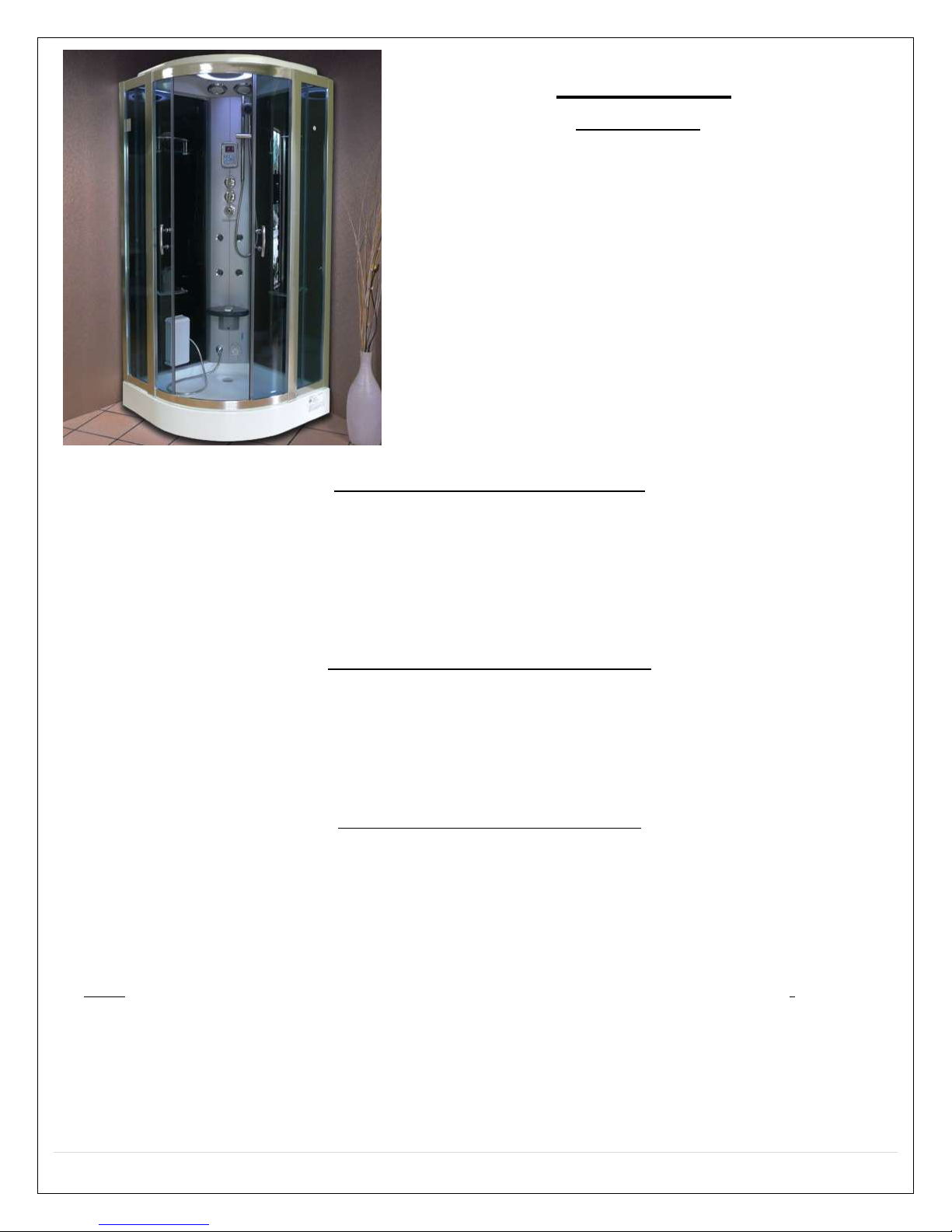
FEATURES
M-A020
Factory tested
Corner Unit
Polished Finish
Phone
Auxiliary RCA input
Steam Aromatherapy Cup
Towel bar & Accessory rack
Blue tinted doors and solid
black walls
Foot Massage
Body Massage Jets
Rainfall Shower Head
Mood light
Sliding Doors
Hand-held Shower w/
Height-Adjustable Bracket
Adjustable Time & Steam
Temperature Settings
Control Panel with Remote
Circulation Fan
Tempered Glass
2.5kW Self-Cleaning Steam
Generator
Folding Seat
Pressure Balance Valve
(optional extra)
FM Transmitter (optional
extra)
4 | P a g e
REV 03/2012
GENERAL INFORMATION
Units come broken down in panels and are assembled with screws, nuts and bolts on site. All seams and
joints are to be caulked with 100% silicone at room temperature (no latex caulking)
Note: It is advised to have base onsite before preparing drain location. All shower bases need to be leveled
in its final resting position, mark the placement, then pull base out and begin assembly.
Access panel near controls panel and jets recommended.
Manufacturer reserves the right to change specs or features at anytime. Please check to confirm
details. 1-866-783-2661

5 | P a g e
REV 03/2012
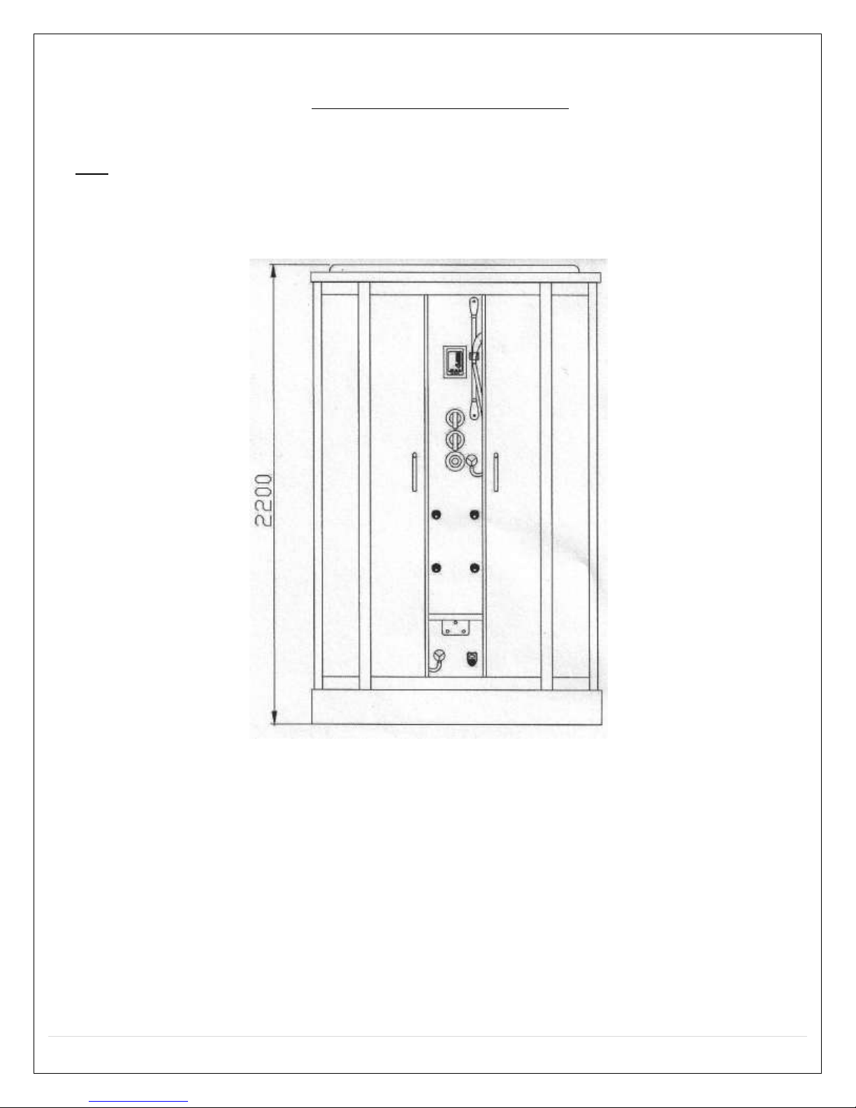
Unit Parameters

6 | P a g e
REV 03/2012
System
Electric Data
Size (mm/inch)
M-A020
Voltage
Power
Frequency
Length
Width
Height
220V
3.5kW
50~60Hz
950/37
950/37
220/86
7 | P a g e
REV 03/2012
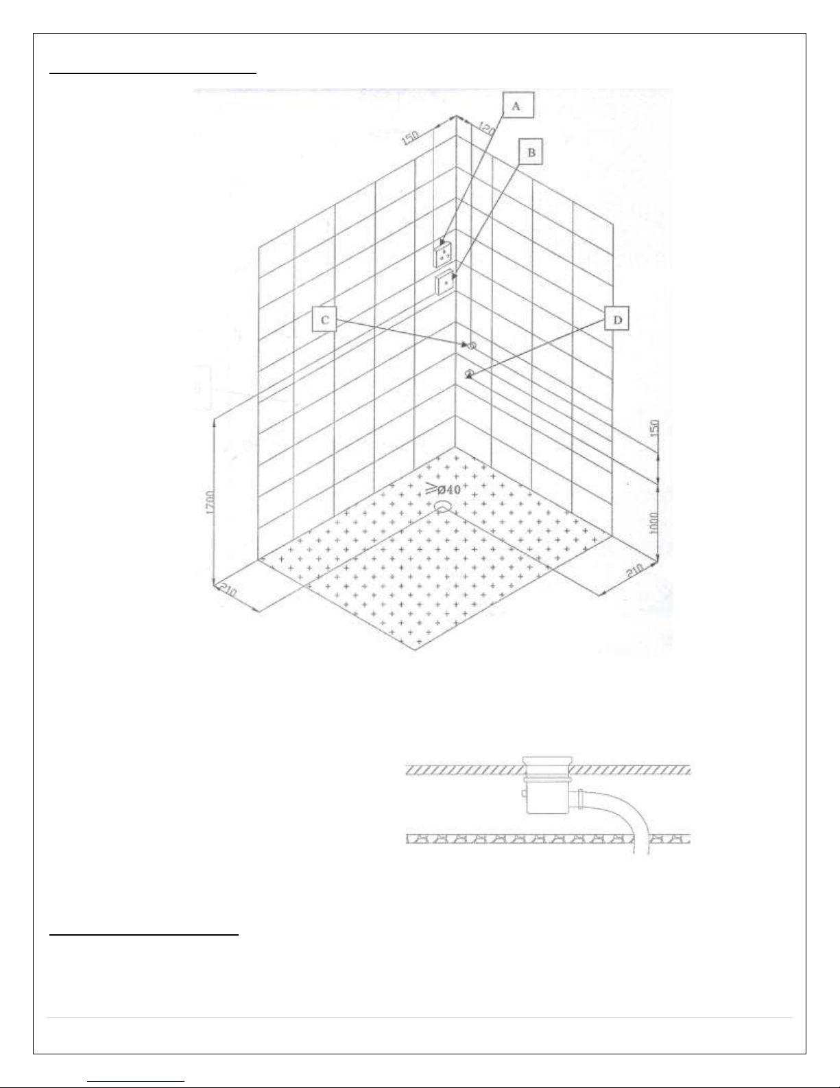
Rough-In Diagram
Diagram Key:
a. Hot Water Inlet
b. Cold Water Inlet
c. Phone Hook-up
d. Power Hook-up
e. Ø40 Drain Hole
Drain Disclosure
NOTE: a flexible drain hose is provided with the unit. We strongly recommend taking off the flex
drain hose and hard pipe the unit into existing drain. This will not void the warranty. Call 866-
STEAM-61 for any questions.
8 | P a g e
REV 03/2012
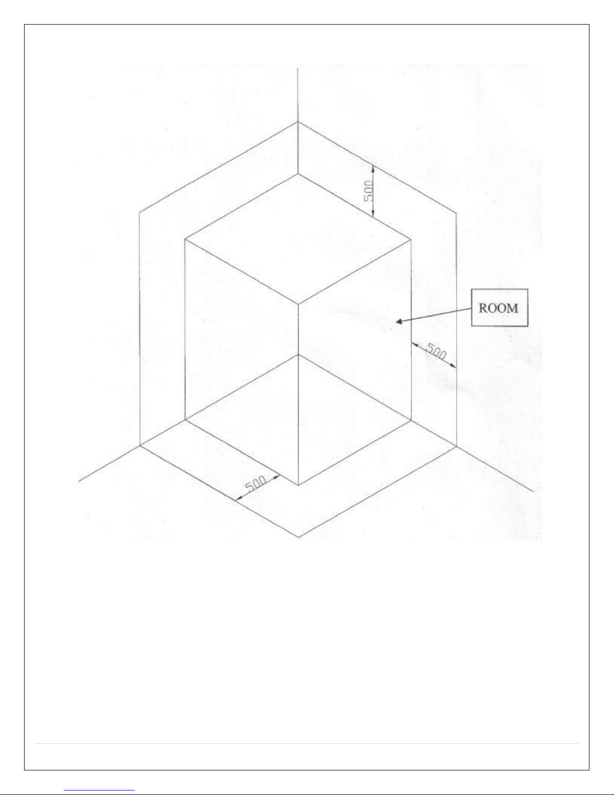
Attention: do not put anything in the safe area, the distance between the top shower cover
and ceiling should be greater than the safe area. Room must be left clear on both sides of the
shower.

9 | P a g e
REV 03/2012
Tools Needed for Installation

10 | P a g e
REV 03/2012
Unit Features Diagram
1. Check the unit as soon as it arrives. Note if there is any shipping damages, then
notify the distributor.
2. Check the water and the electronic system and ground are suitable for
installation.
3. At least two people will be needed for installation.
4. The following parts should be in the packaged boxes:
1. M6X20 screw
2. Top Cover
3. ST4X10
4. Aluminum Panel (Main)
5. Hand Held Shower
6. Sliding Bar
7. Control Panel
8. Shelf
9. Diverter Valve
10.Side fixed glass
11.Acupuncture jets
12.Towel bar
13.Seat
14.Steam Outlet
15.Foot massage
16.Tray/Base
17.Top Rail
18.ST4X30
19.Corner Aluminum Rail
20.Front fixed panel
21.Handle
22.Movable door
23.Rollers

11 | P a g e
REV 03/2012
Installation
1. Connect the shower hose with shower outlet (on the back panel), then put the hand-
held shower on the sliding bar.
.
2. When using the foot massage, open the cover first.
12 | P a g e
REV 03/2012
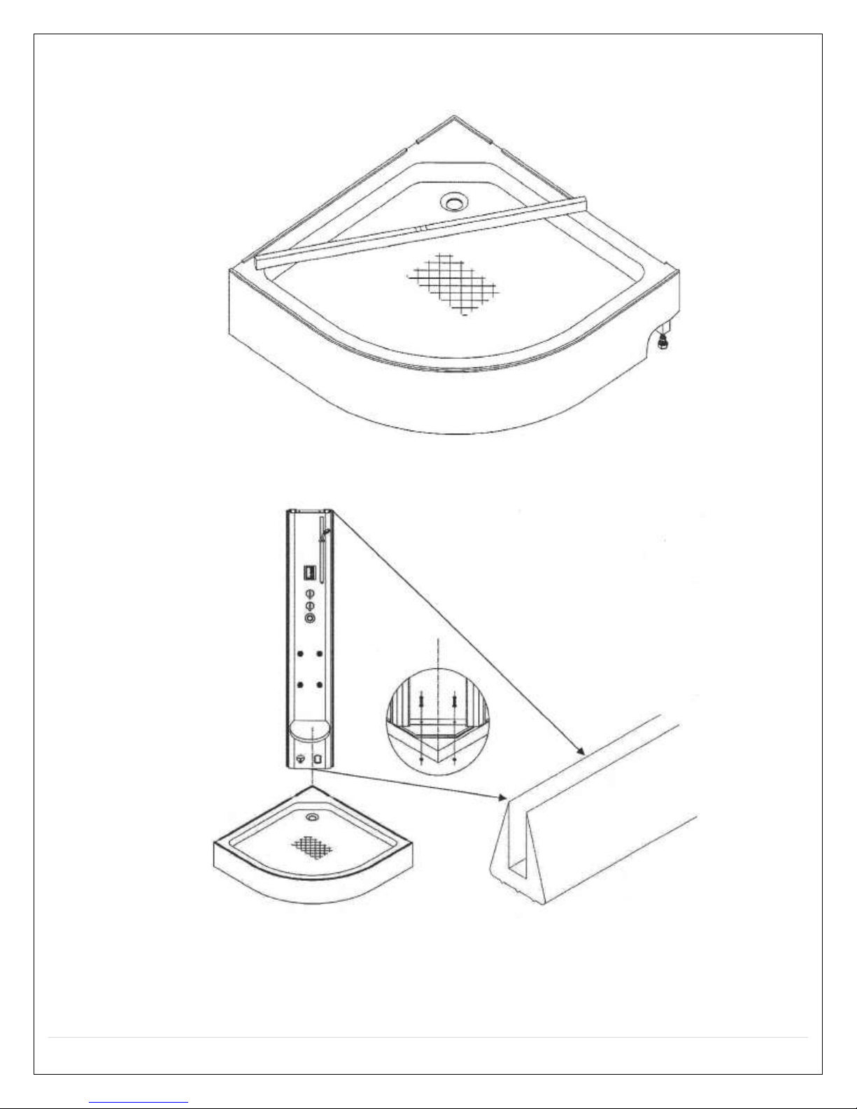
3. Put the shower tray on the selected area (using are of this product), check whether it
is leveled, then adjust the foot screws (under the shower tray) to make sure it is
leveled. Note: level all feet on the supporting bar.
4. Clip the rubber strips as shown onto the aluminum column, uplift the aluminum
column onto the bottom basin, and connect it with the bottom basin through M6X25
screws.
Note: Please use 100% silicone caulk on all seams, joints, and check all fittings and
connections for tightness.
13 | P a g e
REV 03/2012
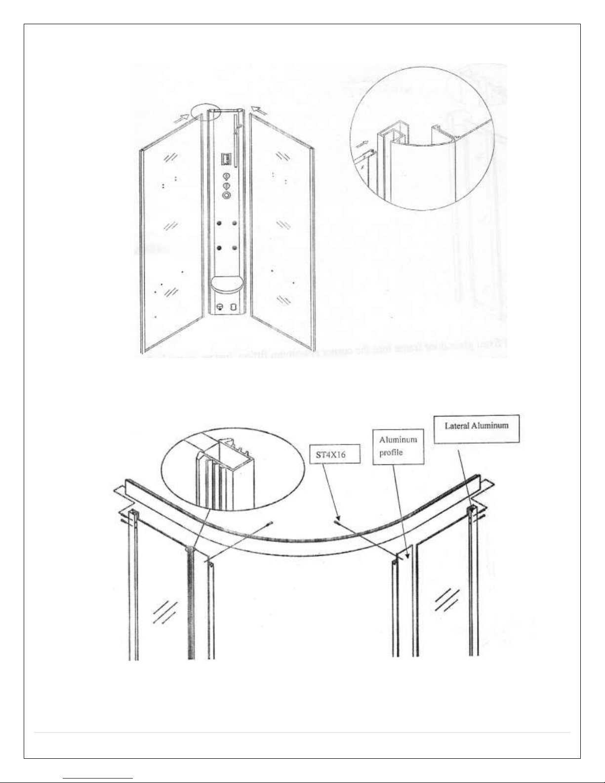
5. Slide the left and right fixed glass into the aluminum column, just as shown in the
diagram.

14 | P a g e
REV 03/2012
6. Slide the completed fixed glass door frame into the corner aluminum fitting, just as
shown in the picture.
7. Uplift the front fixed glass door frame onto the bottom basin, and slide the corner
aluminum rail into the two fixed glass doors.
15 | P a g e
REV 03/2012
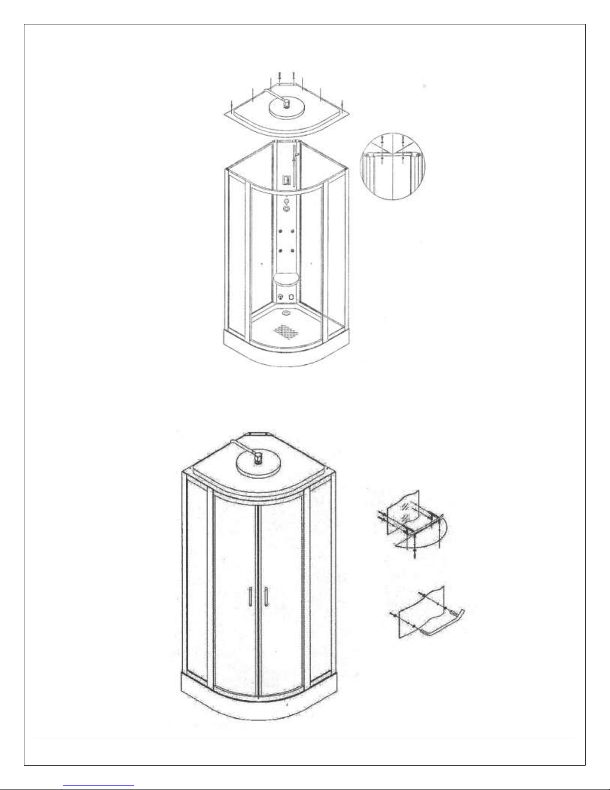
8. Place the roof onto the booth, connect the roof and the aluminum backboard with
M6X16 screws, and connect it with the aluminum fitting by ST4X16.
9. Adjust the rollers to allow the doors to move freely, finally, install the handles and the
shelf in accordance with the method shown.
16 | P a g e
REV 03/2012
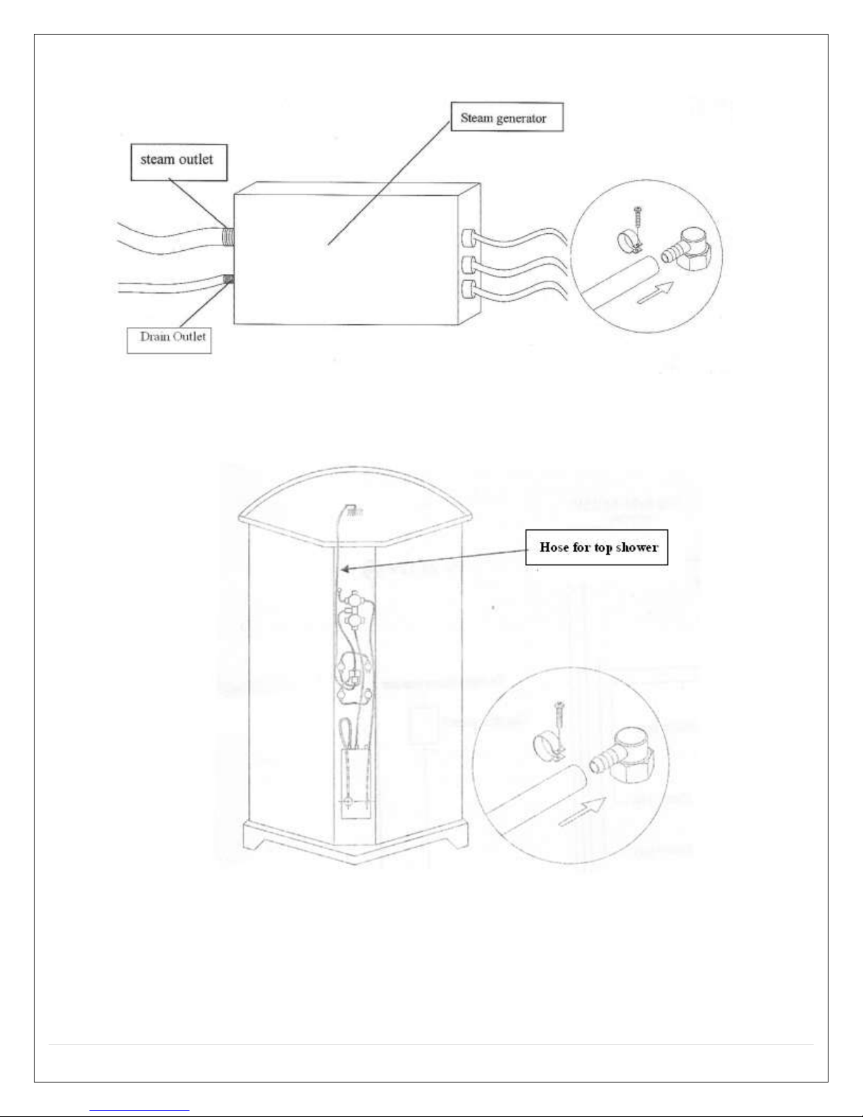
10. Connect the pipes in the package with the drain outlet on the steam generator
and the drain exit; fasten it with the M4X16 round head screw; as shown.
11. Pull the top shower pipe through hole on the top cover. Connect to the shower
head.
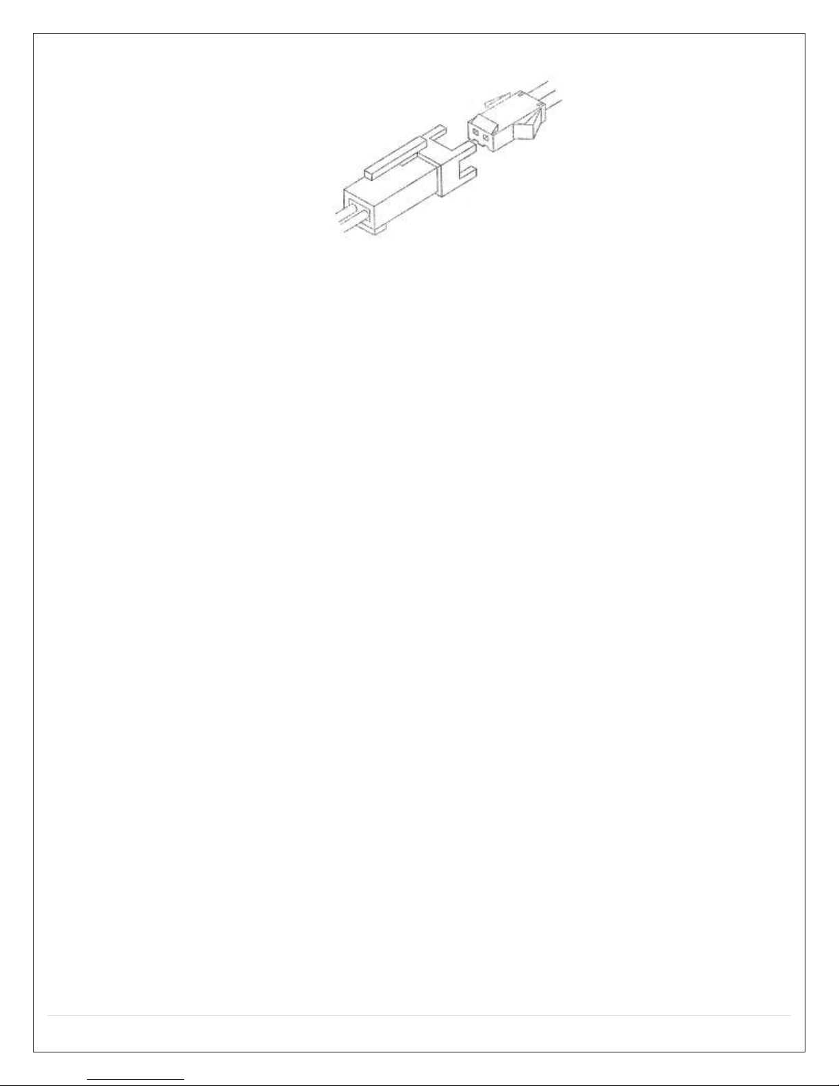
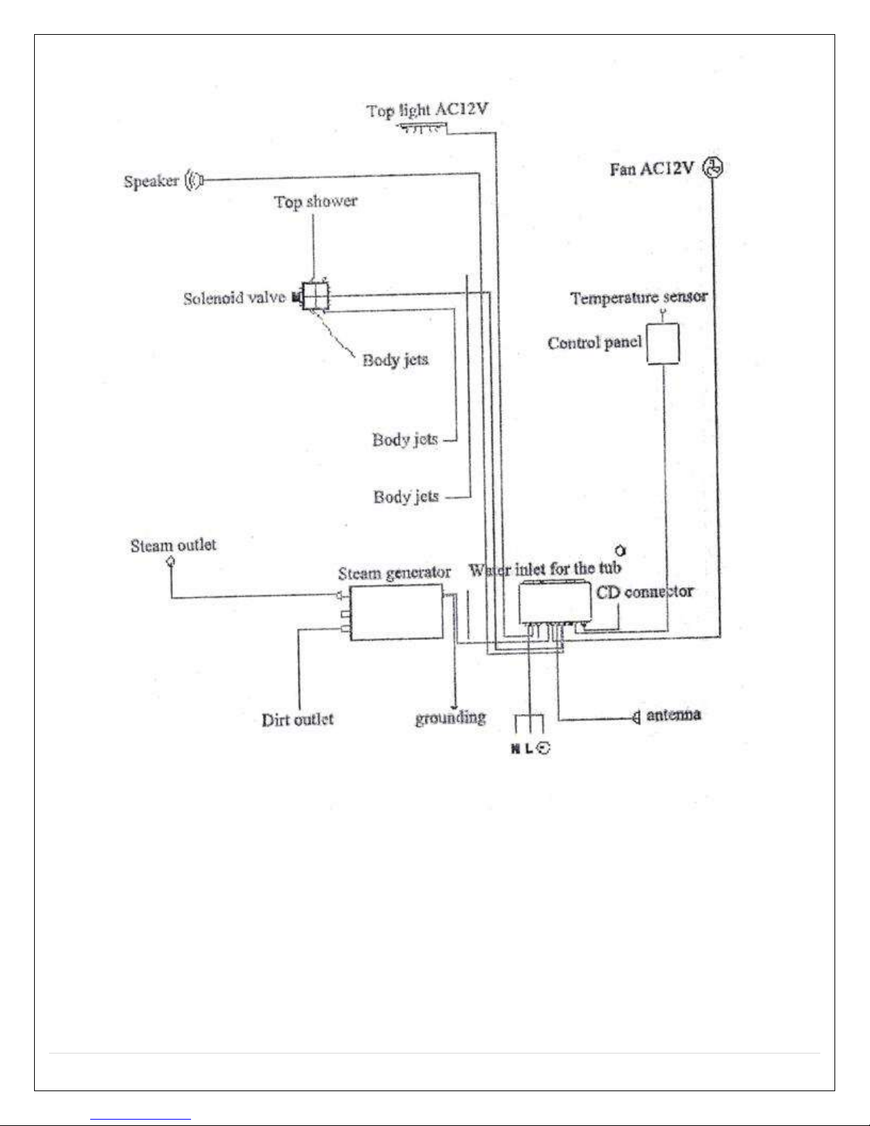
12. Please, refer to the labels on the wires; connect the wires sharing the same
sign.
17 | P a g e
REV 03/2012
13. Connect the braided cold and hot water hoses, the red one is for hot water,
blue is for cold.
14. Seal the connection with Teflon tape.
18 | P a g e
REV 03/2012
220V
50-60Hz
19 | P a g e
REV 03/2012
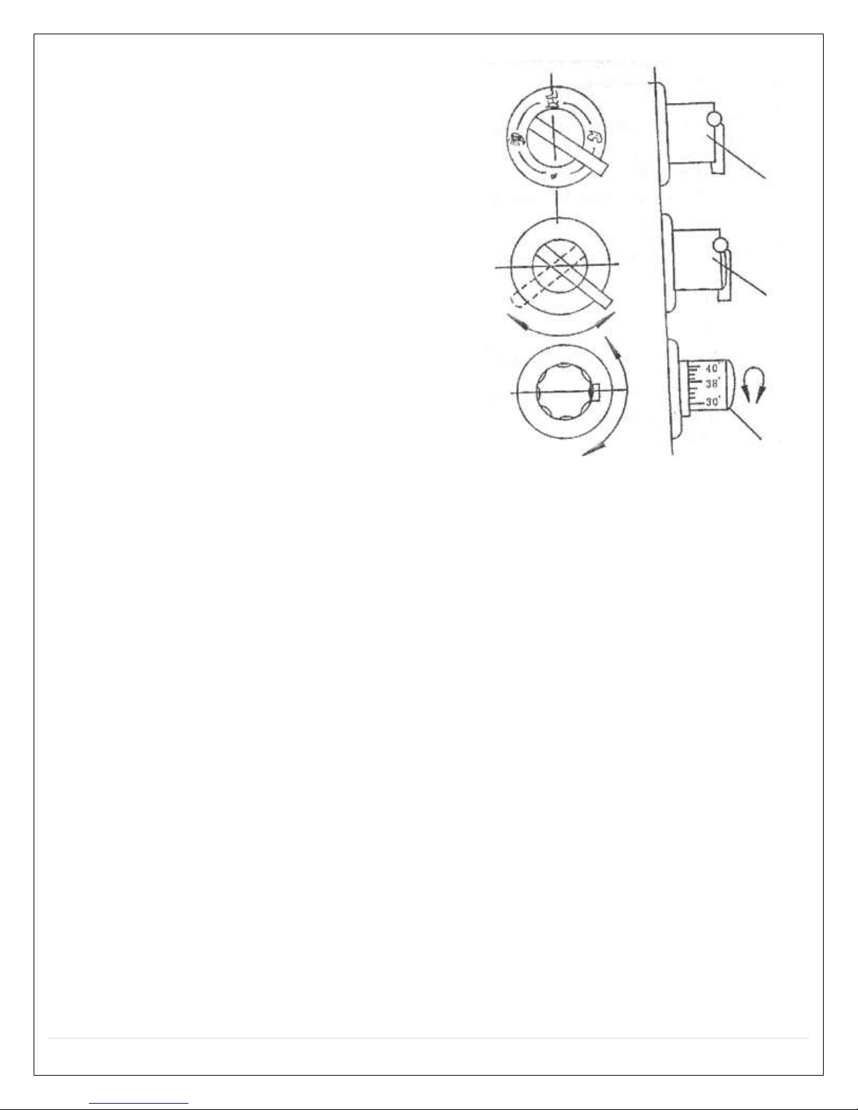
After connecting the hot and cold water,
rotate the temperature knob, in accordance
with the temperature scale in the dial, you
can adjust the different temperature, rotate
the middle knob, this shuts the water on
and off. Rotate the water diverter function
knob; you can use the different shower
functions.
The thermostatic valve faucets are different
with the general faucet, when using the
thermostatic valve faucet, the desired results
can only be achieved after the following
terms and conditions are available.
The water pressure of the hot and cold water
should remain consistent
If a relatively large water heater has been
equipped, the heat required should be
satisfied
Specific methods of operation
Thermostat valve adjustment
oIf the temperature control faucet has
been equipped in the steam room, a sudden change of water temperature
which may leads to burn the body by hot water, or stimulate the skin by cold
water will be eliminated, the function is controlled by the Italian thermostat
valve-core which uses the advance shape alloy memory technology (SAM) to
control the water temperature. On thermostat adjusting hand wheel, the 30°-
50° temperatures are marked there, the temperature within the scope are
optional for the users. If the user rotates the wheel at 38°, it will be locked,
and the water will always flow at 38°. If the user wants to change the
temperature, he/she can press the position lock bar on the thermostat
adjusting hand wheel, and then adjust the temperature to the desired value.
Note: the temperature setting of the hot water tank and the cold water will vary the
temperature valves on the control. Seasonal temperature change will affect the
temperature also.

20 | P a g e
REV 03/2012
Troubleshooting Guide
Situation
Malfunction
Display
Possible Failure Reason
Solutions
Will not run
No display on the
monitor
1. Power line not connected or no
power supply
2. Insufficient power
3. 2A fuse damaged
4. Circuit breaker or OFT switch
damaged.
1. Correctly connect or wait for the
electricity supply to resume.
2. The power must reach the required
standard.
3. Replace the 2A fuse.
4. Replace or reset breaker
Switch failure
Power off right after
turned on
1. Leakage protection switch
damped or damaged
2. Short circuit
1. Replace the switch
2. Recheck the circuit for shorts
Shut off
spontaneously
Indicating light is on
1. Inlet or outlet valve damaged
2. The drainage of the outlet valve
got stuck
1. Replace the inlet or outlet valve
2. Clean out the drain pipe
Indicating light is off
1. Electronic components damaged
2. Cables loose
1. Repair or replace the relevant
component
2. Reconnect the cables
No steam coming
out
1. No water coming in the steam
generator
2. Water pressure too low
3. Heating element in the steam
generator is broke
4. Lack of water
5. Steam pipe is blocked
6. Haven’t reached the required
heating time
7. The indoor temperature is higher
than the set temperature
1. Wait for the water pressure to build
up
2. Install booster on the main water
pipe
3. Replace with a new one
4. Check the inlet valve
5. Remove the obstruction or replace
the pipe
6. Wait for a while (2-3minutes)
7. Set a higher temperature or wait for
it to cool down
Self protection
1. Lack of water pressure
2. Inlet or outlet valve got stuck
3. Drain pipe blocked
4. Steam pipe blocked
1. Install booster
2. Clean out the obstruction
3. Same as above
4. Clean the steam pipe
Overheating
1. The set temperature is too high
2. Temperature sensor fails to work
1. Set a lower one
2. Replace with new one
Steam cut off
1. Set time’s up
2. Set temperature is too low
3. Electronic component (heating
element) damaged
1. Reset the time
2. Set a higher one (cannot be lower
than the temperature in the room)
3. Repair or replace
Water leaks from the
steam outlet
1. Water sensor is out of control
2. The circuit in charge of checking
the water level is out of control
1. Check the water sensor
2. Check the components of that circuit
No sound comes
from the speaker
Monitor is working
1. No FM signal
2. No sound
3. Speaker damaged
4. Antenna is loose
1. Readjust the channel
2. Increase volume
3. Replace a new one
4. Reconnect it and adjust the position
Monitor is not working
1. Circuit or electronic components
damaged
2. Cable loose and/not connected
1. Replace it
2. Reconnect it or replace it
Attention: within the warranty time, do not break the seal on the electrical box and the steam generator on your own. Do
not repair or replace the circuit on your own. If any problems occur, please contact the local distributor.
Table of contents
Other Steam Planet Plumbing Product manuals

Popular Plumbing Product manuals by other brands


Moen
Moen Kingsley 6121 Series installation instructions

DURAVIT
DURAVIT P3 Comforts 720151 Mounting instructions

Imi Heimeier
Imi Heimeier Regulux N operating instructions

American Standard
American Standard 403 installation instructions

Spectrum Brands
Spectrum Brands Pfister Rhen LG6-1RH1 Quick installation guide

Booth & Co
Booth & Co AXBRIDGE BC-AXB-153-CP user guide


