Imi Heimeier Regulux N User manual
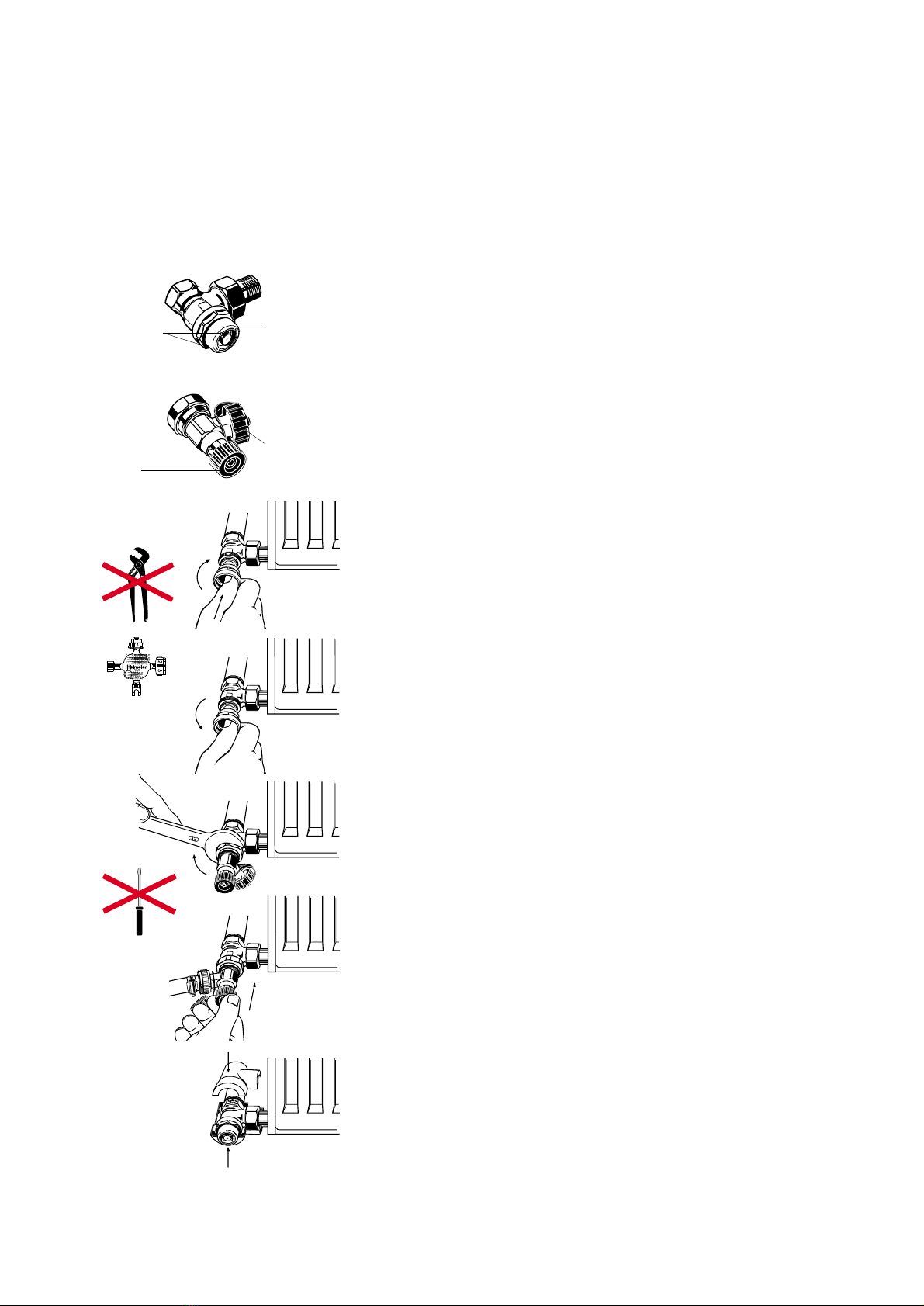
Zamykanie
Odkr´ciç ko∏pak zamykajàcy. Stron´ czo∏owà nasadziç na trzpieƒ
zaworu i kr´ciç w prawo do ca∏kowitego zamkni´cia zaworu. (Rys.1 .
Nakr´ciç ko∏pak zamykajàcy i dociàgnàç r´cznie.
Trzpieƒ wolno obs∏ugiwaÊ tylko pos∏ugujàc si´ ko∏pakiem zamykajàcym
lub uniwersalnym kluczem firmy Heimeier. Nie u˝ywaç szczypiec
i innych narz´dzi.
Zastrze˝one zmiany techniczne
0311-00.480 05.98
ko∏pak zmykajàcy
Odwadnianie
Zamknàç z∏àczk´ powrotu (patrz Zamykanie .
Wykr´ciç a˝ do oporu pokr´t∏o urzàdzenia nape∏niajàcego
i opró˝niajàcego, urzàdzenie opró˝niajàce nakr´ciç na z∏àczk´
powrotu i lekko dociàgnàç kluczem maszynowym (32 mm (Rys. 3 .
Króciec przy∏àczeniowy ustawiç na pozycji przez obracanie
i odkr´ciç ko∏pak ochronny. Podstawiç naczynie zbiorcze lub
przy∏àczyç z∏àczk´ w´˝a. Wsunàç pokr´t∏o delikatnie obracajàc
tak, by trzpieƒ pokr´t∏a wpasowa∏ si´ w zawór odwadniajàcy
(Rys. 4 . Otworzyç proces opró˝niania przez obrót w lewo pokr´t∏a.
W celu zamkni´cia zaworu odwadniajàcego przekr´ciç pokr´t∏o
w prawo do lekko wyczuwalnego oporu, a nast´pnie ca∏kowicie je
odciàgnàç. Pokr´t∏o ca∏kowicie wyciàgnàç i odkr´ciç urzàdzenie.
Nakr´ciç ko∏pak zamykajàcy i dociàgnàç r´cznie.
Opró˝nianie wykonywaç tylko przy pomocy urzàdzenia nape∏-
niajàcego i opró˝niajàcego. Nie u˝ywaç ˝adnych wkr taków
lub innych narz dzi.
Przed odkr ceniem urzàdzenia nape∏niajàcego i opró˝niajàcego
musi byç najpierw wyciàgni te pokr t∏o.
Podczas procesu opró˝niania grzejniki si zapowietrzajà.
Nastawianie wst pne
Zamknàç z∏àczk´ powrotu (patrz Zamykanie .
Nast´pnie ustaliç stopieƒ otwarcia odpowiednià liczbà obrotów
ko∏pakiem w lewo. (Rys. 2 . Jako pomoc w nastawianiu s∏u˝à
cztery znaki na stronie czo∏owej ko∏paka. Po dokonaniu czynnoÊci
nastawiania nakr´ciÊ ko∏pak zamykajàcy i dociàgnàç r´cznie.
Z∏àczka powrotu
Urzàdzenie nape∏niajàce i opró˝niajàce
znaki do wst´pnego
nastawiania
króciec przy∏àczeniowy,
z mo˝liwoÊcià obrotu
360°
pokr´t∏o
Uniwersalny klucz*
Nr zamówieniowy
0530-01.433
Rys. 1
Rys. 2
Abb. 3
Rys. 4
Rys. 5
Zastosowanie nowych technologii i u˝ycie nowych materia∏ów po-
woduje równie˝ zmian´ utartych sposobów post´powania podczas
obs∏ugi z∏àczek powrotu. Cz´Êç wewn´trzna z∏àczki powrotu
Regulux N jest wykonana z tworzywa sztucznego ”High-Tech”.
Uszczelnienie sto˝ka odcinajàcego wzgl´dem gniazda zaworu
wykonane jest w sposób mi´kko uszczelniajàcy za poÊrednictwem
pierÊcienia uszczelniajàcego O-Ring. Zmniejszony dzi´ki temu wydatek
si∏y czyni zb´dnym pos∏ugiwanie si´ zwyk∏ymi narz´dziami.
Os∏ona zaworu
Z∏àczka powrotu Regulux N mo˝e byç równie˝ dostarczana
z os∏onà wykonanà z tworzywa sztucznego dla Êrednic nominalnych
DN 10 i DN 15. W celu monta˝u obydwie po∏ówki os∏ony przydziela si´
do odpowiedniej strony korpusu i dociska si´ ze sobà (Rys. 5 .
Ko∏ki ustalajàce w jednej po∏ówce os∏ony muszà le˝eç na przeciw
otworów w drugiej po∏ówce. Na wewn´trznej stronie po∏ówek os∏ony
oznaczone jest po∏o˝enie przy∏àcza rurowego, postaç konstrukcyjna
i Êrednica nominalna przynale˝nej armatury.
Instrukcja monta˝u i obs∏ugi
Regulux N
Grzejnikowy regulator przep∏ywu (z∏àczka powrotu)
z urzàdzeniem nape∏niajàcym i opró˝niajàcym
* Alternatywnie do ko∏paka zamykajàcego pe∏ni funkcj´
klucza do otwierania, zamykania i ustawiania nastawy
wst´pnej na z∏àczce Regulux N jak równie˝ do obs∏ugi
dolnej cz´Êci zaworu termostatycznego V-exakt/F-exakt,
g∏owicy termostatycznej B, z∏àczki przy∏àczeniowej
Vekolux N i zaworu odpowietrzajàcego grzejnika.

Regulux N
Radiator lockshield with fill and drain-off device
Operating instructions
Raccord de retour avec vidange
Mode d’emploi
Radiator-voetventiel met Vul- en aftapset
Bedieningsvoorschriften
The application of new technologies and the
use of new materials change also the usual
way and mannar of operating and handling
the lockshield. The internal components of
Regulux N lockshield are manufactured out
of high tech. plastics. Sealing of the shutoff
cone opposite the valve seat is now
performed by a soft-structured sealing O-ring.
The thus reduced required force renders the
use of standard tools unnecessary.
Shut-off
Unscrew the closing cap and place this cap
with its front side on the spindle and rotate
until the spindle will engage (Fig no. 1 .
Thereafter, close the lockshield by rotating
clockwise. Rescrew the closing cap and only
finger-tight.
Only operate the spindle with the closing
cap or the Heimeier universal key.
Don‘t use a pair of pliers or and other tools.
Preadjustment
Close the lockshield (see - "shut-off" above .
Afterwards effect the predetermined setting
by rotating the cap anti-clockwise (see Fig. No 2 .
The four (4 markings on the front side of
the cap serve as setting aid. After having
terminated the setting operation the closing
cap must be screwed on and be finger-tightened.
Drain-off
Close the lockshield (see - "shut-off" above .
Pull the handwheel of the fill and drain-off
device back until reaching the stop, screw
the fill and drain-off device an the lockshield
and use an spanner (SW 32 and tighten
slightly only (see Fig no 3 .
Turn the connecting screw socket to the
required position and unscrew the protective
cap. Place a collecting vessel beneath or
connect a drain hose. Push in the handwheel
and rotate the said wheel applying only little
pressure until same will engage (see Fig. No 4 .
For draining-off rotate the handwheel anti-
clockwise until reaching a opening stop.
To close the drain-off device rotate and,
thus, screw in the handwheel clockwise
applying a steady pressure until feeling a
certain slight resistance. Pull the handwheel
back completely and unscrew the fill and
drain-off device. Replace the closing cap in
position, screw same on and finger-tighten
only.
The drain-off facility must only be operated
with the fill and drain-off device.
Don‘t use screw drivers or any other tools.
Please be aware that, the handwheel of
the fill and drain-off device must have
been pulled back prior to unscrewing the
said device.
During the draining-off operation the
radiator should be vented.
Valve cover
The Regulux N lockshield can be supplied
with nominal (standard widths DN 10 and
DN 15 and also with a plastic cover.
Mounting will be done by assigning both
halves of the cover to the relevant body side
and then they are pressed together. The
retaining pins in one half must be located
opposite the holes of the other half. On the
inside of the cover halves the position of the
pipe connection, the type data and the
nominal width of the appropriate valve are
indicated.
We reserve the right to introduce technical
alterations without previous notice.
Door gebruik te maken van nieuwe technologieën
en het toe passen van nieuwe materialen,
verandert ook de gebruikelÿke/traditionele
bediening van de aansluitkoppelingen.
Het binnenste van de Regulux N aansluit-
koppelingen is uit High-Tech kunststof
vervaardigd. De afdichting van de afsluitkogel
ten op zichten van het ventielhuis geschiedt
zeer licht door middel van een O-Ring.
De hierdoor gereduceerde afsluitkracht maakt
toepassing van gebruikelÿke gereedschap
overbodig.
Afsluiten
Afsluitkap afschroeven, met de sterzijde op de
spindel zetten en verdraaien, tot het in elkaar
sluit (afb.1). Aansluitend het voetventiel, door
met de klok mee te draaien, sluiten. Afsluitkap
op draaien en handvast aandraaien.
Spindel alleen met afsluitkap of universele
instelsleutel bedienen.
Geen tang of ander gereedschap gebruiken.
Voorinstellen
Voetventiel sluiten (zie afsluiten) Aansluitend
de gewenste voorinstelling instellen, door het
naar linksdraaien van de kap (afb. 2).
Als instelorientatie dienen de vier markeringen
op de sterzijde van de kap. Na de instelhandeling
de afsluitkap op draaien en handvast aandraaien.
Aftappen
Voetventiel sluiten. (zie afsluiten) Handknop
van het vul- en aftapset tot de aanslag
terugtrekken, vul- en aftapset op de
aansluitkoppeling schroeven en met een
steecksleutel (SW32) licht aantrekken (Afb.3).
Aansluitpunten(nokken) doordraaien en in
positie brengen en beschermkap afschroeven.
Lekbakje aanbrengen of aftapslang aansluiten.
Handknop inschuiven en onder lichte druk in
elkaar laten vallen (afb. 4), vul- en aftapmoge-
lijkheid door naar linksdraaien van de handknop
openen. Om af te sluiten het handvat van het
vul- en aftapset onder voelbare druk naar
rechts draaien en tot een licht voelbare
weerstand aandraaien. Afsluitkap op draaien
en handvast aandraaien.
Voor het aftappen alleen het vul- en
aftapset gebruiken. Geen schroevedraaier
of ander gereedschap toepassen.
Het handvat van de vul- en aftapset moet
teruggetrokken zijn, voordat deze
afgeschroeft wordt.
Tijdens het aftappen de radiator beluchten.
Ventiel bekleding
Het Regulux N voetventiel is in de doorlaten
DN 10 en DN 15 ook met bekleding uit
kunststof leverbaar.
Voor de montage worden beide helften van
de bekleding op de overeenkomstige zijden
van het huis aangebracht en samengedrukt.
De borgpen van de ene helft moeten tegenover
de boring van de andere helft liggen. Aan de
binnenkant van de bekledingshelften zit de
aanduiding voor de buisaansluitingen, de
bouwvorm en de doorlaat van het overeen-
komstige armatuur.
Technische wijzigingen voorbehouden.
L‘application de nouvelles technologies et des
nouvelles matières provoquent des changements
dans les systèmes de raccords de retour.
L‘intérieur du raccord de retour Régulux N est
fabriqué en matière synthétique high-tech.
L‘étanchéité du piston et du siège de la vanne
est faite par un joint torique. Ce type de système
demande beaucoup moins de force pour régler
et l‘utilisation d‘outils standards n‘est plus
nécessaire.
Fermer
Démonter le couvercle, mettre la face
supérieure (en forme d‘étoile) sur la tige du
Régulux N. (Fig. 1) Tourner dans le sens des
aiguilles d’une montre jusqu‘au bout.
Remonter le couvercle et serrez à la main.
Actionner le raccord uniquement avec le
couvercle d’origine ou la clé universelle
d’Heimeier.
Ne pas utiliser de pince ou d’autres outils.
Prérégler
Fermer le raccord de retour (voir fermer).
Régler le clapet en tournant en sens inverse
des aiguille d‘une montre, en utilisant le
couvercle. (Fig. 2) Les quatre marques sur la
face supérieure du couvercle servent comme
aide au réglage. Après le réglage, remonter le
couvercle et serrer à la main.
Vidanger
Fermer le raccord de retour (voir fermer).
Raccorder le dispositif de vidange/remplissage
avec poignée retirée. Serrer légèrement avec
une clé 32 (Fig. 3).
Ensuite mettre en position le raccord de
vidange et enlever le capuchon. Placer un
récipient en dessous ou raccorder un flexible
d’évacuation. Pousser la poignée contre la tige
du raccord de retour (Fig. 4).
Pour vidanger, tourner la poignée de vidange
vers la droite jusqu‘au moment d‘une résistance,
puis retirer la poignée. Déserrer le dispositif de
vidange. Reserrer le couvercle à la main.
Vidanger seulement avec le dispositif de
vidange/remplissage. Ne pas utiliser de
tournevis ou d‘autres outils.
La poignée du dispositif de
vidange/remplissage doit être retirée avant
de monter le dispositif sur le raccord de
retour.
Pendant la vidange, ouvrir le purgeur du
corps de chauffe.
Protection
Les diamètres DN 10 et DN 15 du Régulux N
peuvent être livrés avec une coquille de
protection synthétique. Pour le montage, les
deux parties de la protection sont placés
autour du raccord. Appuyer sur les deux
parties pour que les tiges d‘une partie entrent
dans les trous de l‘autre. A l‘intérieur de la
protection synthétique, vous trouverez le
marquage qui indique la position du raccord,
la forme et sa taille.
Sous réserve de modifications.
Other Imi Heimeier Plumbing Product manuals


