Steam Planet M-A021 User manual

1 | P a g e
REV 03/2012
Installation & Operation Manual for M-A021

2 | P a g e
REV 03/2012
Table of Contents
Specification Page …………………………………………… 3-4
Unit Parameters …………………………………………… 5
Drain Disclosure …………………………………………… 5
Tools Need for Installation …………………………………………… 6
Packing List …………………………………………… 7
Installation Manual …………………………………………… 8-13
Troubleshooting …………………………………………… 14
Replacing Door Rollers …………………………………… 15
Cleaning & Maintenance …………………………………………… 16
Shower Control Panel …………………………………………… 17
Remote Control …………………………………………… 18
Function Instructions …………………………………………… 19-20
Technical Data ……………………………...…………… 21
Thank you for selecting Steam Planet Corp Computerized Steam Room, we hope that our
exquisite design will meet your life’s needs; it’s our honor to promote your health and
longevity with comfortable enjoyment.
In order to operate and use the product well, please read carefully and follow all
instructions provided in this User’s Manual. We are dedicated to providing satisfied service
for you.
Our company reserves the right to change the Manual. The manual takes effect since the
date it is published. This manual shall prevail if there’s any difference between this and
previous documents and manuals.
Thanks for your support.
3 | P a g e
REV 03/2012
TECHNICAL INFORMATION
Materials: Acrylic, Aluminum, Tempered Glass
Power Supply: 220V
Steam Ready: 2-5 MIN
Dimensions: 47 x 33 x 87 IN
ELECTRICAL INFORMATION
1 dedicated 12-2 line for steam (line 1, line 2, and ground)
220 volt, 20 amp GFCI breaker
There is a length of wire from the control box supplied to connect to power source.
PLUMBING REQUIRMENTS
The unit is equipped with hot and cold, metal braided ½ inch water supply hose with ½ national pipe
thread.
Need to install hot and cold shutoffs with ½ -male national pipe thread (not included).
Supply hoses are to connect from the faucet manifold on the unit to the shutoff valves.
All water jet features are pre plumbed with reinforced braided flexible supply hose
All fixtures and fittings must be checked for tightness as they may have been loosened during
transport.
Access panel area recommended.
Note: The flexible drain hose included with this unit is for installation into a floor drain only.
Substituting the existing drain setup for a setup of the installers’ choice will not void the warranty of
the unit as long as there is no evidence of misuse or damage to the base. If the substitute drain
system is used, a 3/8 in stub must be added to the main shower drain line to connect the steam
generator’s automatic flushing drainage hose.
Please call the manufactured for updated drain info 1-866-STEAM-61
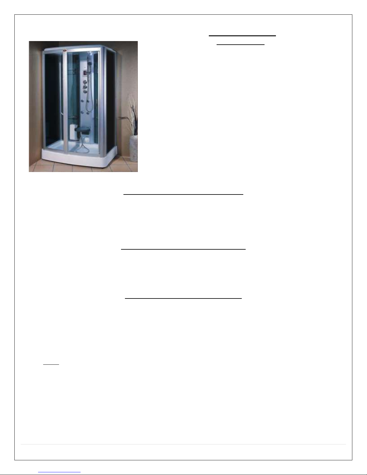
M-A021
FEATURES
Factory tested
Polished Finish
Blue tinted doors/sides and
solid black rear walls
Phone
Auxiliary RCA input
Steam Aromatherapy Cup
Towel bar
Accessory rack
Door slides from right to left
Foot Massage
Body Massage Jets
Rainfall Shower Head
Folding Seat
Hand-held Shower w/ Height-
Adjustable Bracket
Water control valve
Adjustable Time & Steam
Temperature Settings
Control Panel with Remote
Circulation Fan
Mood Light
2.5kW Self-Cleaning Steam
Generator
Tempered Glass
Pressure Balance Valve
(optional extra)
FM Transmitter (optional
extra)

4 | P a g e
REV 03/2012
GENERAL INFORMATION
Units come broken down in panels and are assembled with screws, nuts and bolts on site. All seams &
joints to be caulked with 100% silicone at room temperature (no latex caulking)
Note: All shower bases need to be leveled in its final resting position, mark the placement, then pull
base out and begin assembly. It is advised to have base onsite before preparing drain location. Access
panel area recommended.
Access panel near controls panel and jets recommended.
Manufacturer reserves the right to change specs or features at anytime. Please check to
confirm details. 1-866-783-2661.
5 | P a g e
REV 03/2012
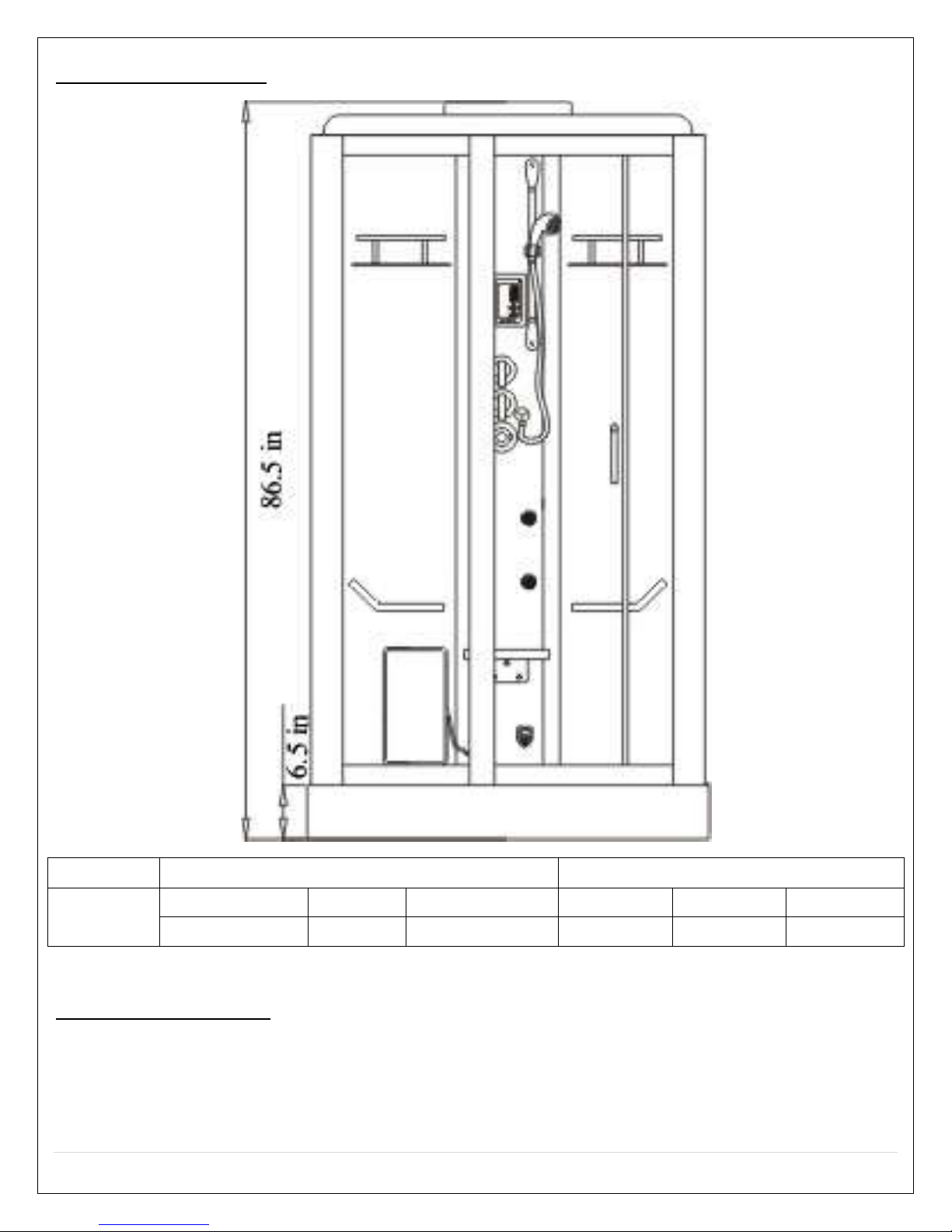
Unit Parameters
System
Electric Data
Size (mm/inch)
M-A021
Voltage
Power
Frequency
Length
Width
Height
220V
2.5kW
50~60Hz
47
33
87
Drain Disclosure
NOTE: a flexible drain hose is provided with the unit. We strongly recommend taking off the flex
drain hose and hard pipe the unit into existing drain. This will not void the warranty. Call 866-
STEAM-61 for any questions.

6 | P a g e
REV 03/2012
Attention: do not put anything in the safe area, the distance between the top shower cover
and ceiling should be greater than the safe area. Room must be left clear on both sides of the
shower.
Tools Needed for Installation

7 | P a g e
REV 03/2012
Packing List
1. Check the unit as soon as it arrives. Note if there is any shipping damages, then
notify the distributor.
2. Check the water and the electronic system and ground are suitable for
installation.
3. At least two people will be needed for installation.
4. The following parts should be in the packaged boxes:
8 | P a g e
REV 03/2012
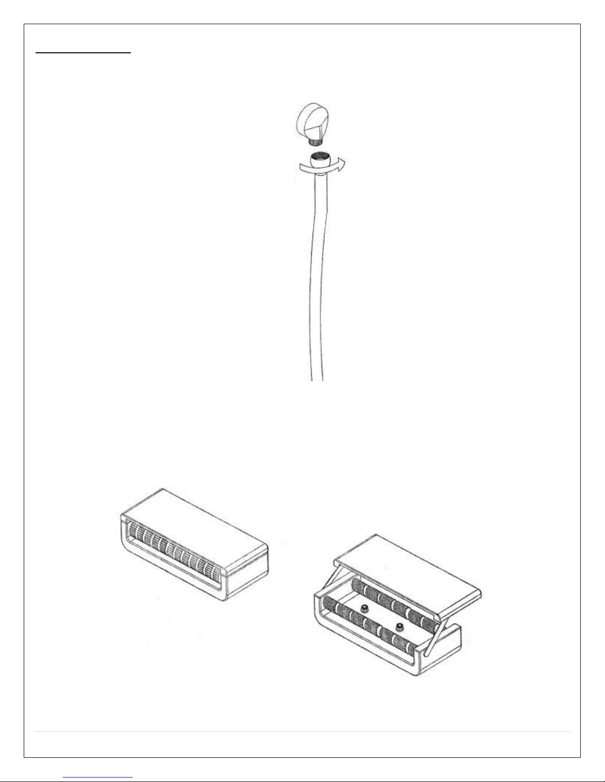
Installation
1. Connect the shower hose with shower outlet (on the back panel), then put the hand-
held shower on the sliding bar.
.
2. When using the foot massage, open the cover first.
9 | P a g e
REV 03/2012
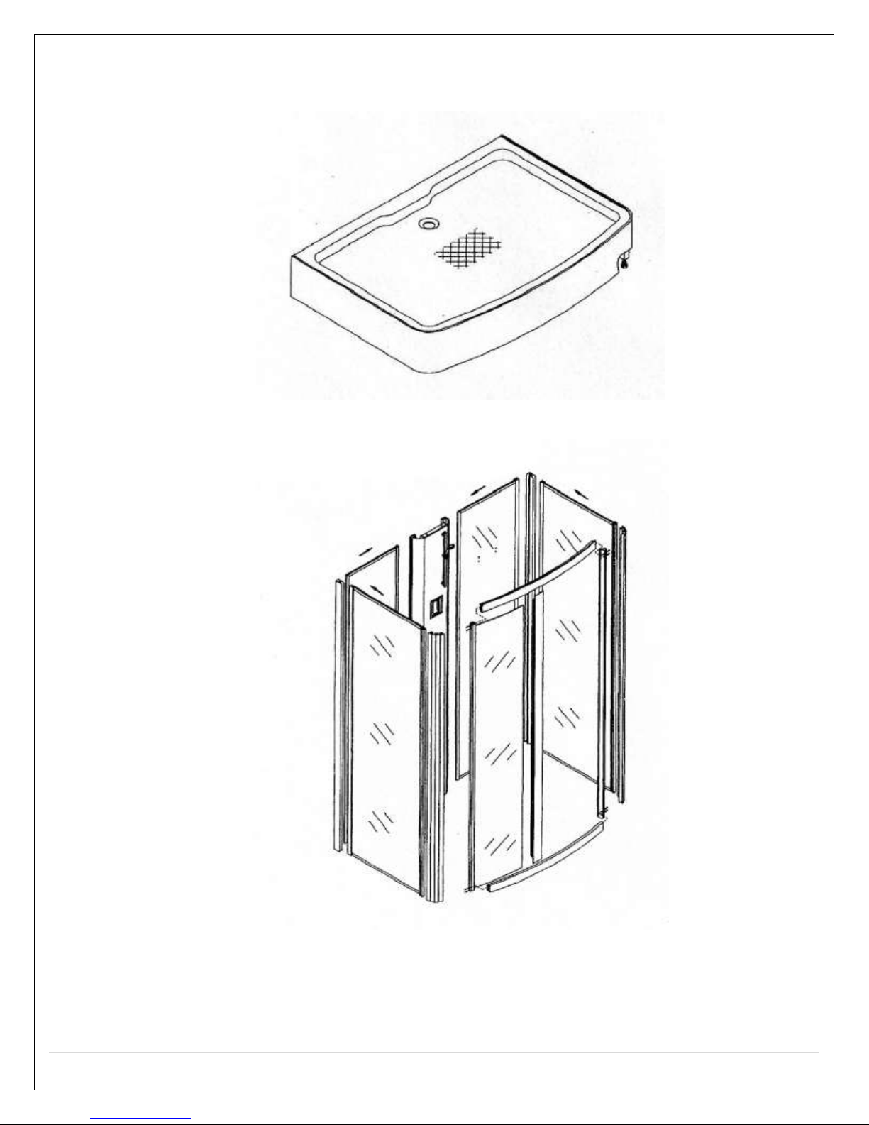
3. Put the shower tray on the selected area (using are of this product), check whether it
is leveled, then adjust the foot screws (under the shower tray) to make sure it is
leveled. Note: level all feet on the supporting bar.
4. Slide the left and right fixed glass into the aluminum column, just as shown in the
diagram.
Note: Please use 100% silicone caulk on all seams, joints, and check all fittings and
connections for tightness.

10 | P a g e
REV 03/2012
5. Place all the glass onto the acrylic shower base.
6. Place the roof of the unit on top of all glass and attach it with ST4x10 to glass doors;
M6x25 screws are used to attach top with control column and shower tray.

11 | P a g e
REV 03/2012
7. Attach shelf and rail as shown.
8. Connect the pipes in the package with the drain outlet on the steam generator and
the drain exit; fasten it with the M4X16 round head screw; as shown.
9. Pull the top shower pipe through hole on the top cover. Connect to the shower head.
12 | P a g e
REV 03/2012
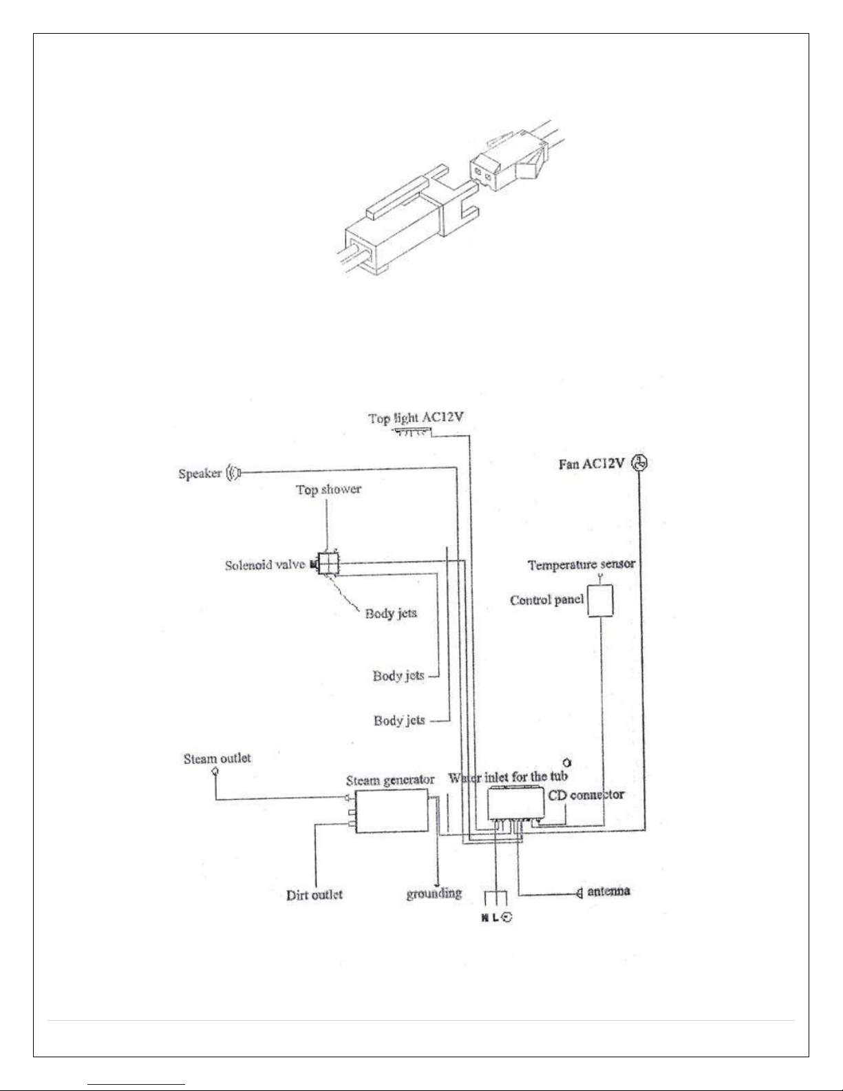
10. Please, refer to the labels on the wires; connect the wires sharing the same
sign.
11. Connect the braided cold and hot water hoses, the red one is for hot water,
blue is for cold.
12. Seal the connection with Teflon tape.
220V
50-60Hz
13 | P a g e
REV 03/2012
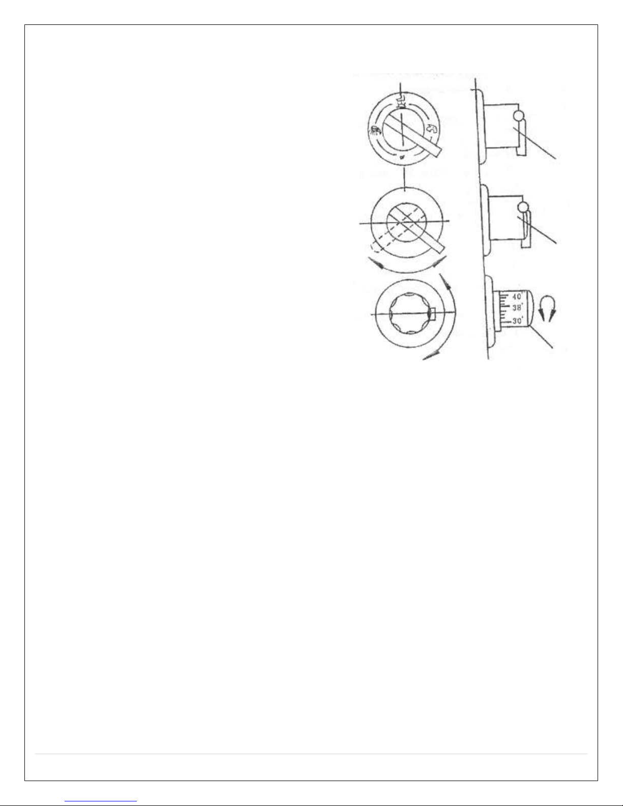
After connecting the hot and cold water,
rotate the temperature knob, in accordance
with the temperature scale in the dial, you
can adjust the different temperature, rotate
the middle knob, this shuts the water on
and off. Rotate the water diverter function
knob; you can use the different shower
functions.
The thermostatic valve faucets are different
with the general faucet, when using the
thermostatic valve faucet, the desired results
can only be achieved after the following
terms and conditions are available.
The water pressure of the hot and cold water
should remain consistent
If a relatively large water heater has been
equipped, the heat required should be
satisfied
Specific methods of operation
Thermostat valve adjustment
oIf the temperature control faucet has
been equipped in the steam room, a sudden change of water temperature
which may leads to burn the body by hot water, or stimulate the skin by cold
water will be eliminated, the function is controlled by the Italian thermostat
valve-core which uses the advance shape alloy memory technology (SAM) to
control the water temperature. On thermostat adjusting hand wheel, the 30°-
50° temperatures are marked there, the temperature within the scope are
optional for the users. If the user rotates the wheel at 38°, it will be locked,
and the water will always flow at 38°. If the user wants to change the
temperature, he/she can press the position lock bar on the thermostat
adjusting hand wheel, and then adjust the temperature to the desired value.
Note: the temperature setting of the hot water tank and the cold water will vary the
temperature valves on the control. Seasonal temperature change will affect the
temperature also.
14 | P a g e
REV 03/2012
Troubleshooting Guide
Situation
Malfunction
Display
Possible Failure Reason
Solutions
Will not run
No display on the
monitor
1. Power line not connected or no
power supply
2. Insufficient power
3. 2A fuse damaged
4. Circuit breaker or OFT switch
damaged.
1. Correctly connect or wait for the
electricity supply to resume.
2. The power must reach the required
standard.
3. Replace the 2A fuse.
4. Replace or reset breaker
Switch failure
Power off right after
turned on
1. Leakage protection switch
damped or damaged
2. Short circuit
1. Replace the switch
2. Recheck the circuit for shorts
Shut off
spontaneously
Indicating light is on
1. Inlet or outlet valve damaged
2. The drainage of the outlet valve
got stuck
1. Replace the inlet or outlet valve
2. Clean out the drain pipe
Indicating light is off
1. Electronic components damaged
2. Cables loose
1. Repair or replace the relevant
component
2. Reconnect the cables
No steam coming
out
1. No water coming in the steam
generator
2. Water pressure too low
3. Heating element in the steam
generator is broke
4. Lack of water
5. Steam pipe is blocked
6. Haven’t reached the required
heating time
7. The indoor temperature is higher
than the set temperature
1. Wait for the water pressure to build
up
2. Install booster on the main water
pipe
3. Replace with a new one
4. Check the inlet valve
5. Remove the obstruction or replace
the pipe
6. Wait for a while (2-3minutes)
7. Set a higher temperature or wait for
it to cool down
Self protection
1. Lack of water pressure
2. Inlet or outlet valve got stuck
3. Drain pipe blocked
4. Steam pipe blocked
1. Install booster
2. Clean out the obstruction
3. Same as above
4. Clean the steam pipe
Overheating
1. The set temperature is too high
2. Temperature sensor fails to work
1. Set a lower one
2. Replace with new one
Steam cut off
1. Set time’s up
2. Set temperature is too low
3. Electronic component (heating
element) damaged
1. Reset the time
2. Set a higher one (cannot be lower
than the temperature in the room)
3. Repair or replace
Water leaks from the
steam outlet
1. Water sensor is out of control
2. The circuit in charge of checking
the water level is out of control
1. Check the water sensor
2. Check the components of that circuit
No sound comes
from the speaker
Monitor is working
1. No FM signal
2. No sound
3. Speaker damaged
4. Antenna is loose
1. Readjust the channel
2. Increase volume
3. Replace a new one
4. Reconnect it and adjust the position
Monitor is not working
1. Circuit or electronic components
damaged
2. Cable loose and/not connected
1. Replace it
2. Reconnect it or replace it
Attention: within the warranty time, do not break the seal on the electrical box and the steam generator on your own. Do
not repair or replace the circuit on your own. If any problems occur, please contact the local distributor.
15 | P a g e
REV 03/2012
Replacing Door Rollers
1. Remove plastic cover from roller
2. Loosen the nut
3. Turn the 6 sides plastic cover Left or Right for release the door on Top and Bottom of
door. Note: the roller is off set to loosen or tighten the door to the frame
4. Take down the door
5. To install new door repeat steps 4,3,2, and 1

16 | P a g e
REV 03/2012
Cleaning and Maintenance
1. When it comes to daily cleaning, liquid detergent and soft cloth should be used. DO
NOT sterilize it with acetone and ammonia detergents. Do not use detergent with
formic acid or formaldehyde. Do not use any abrasive cleaners.
2. To apply with some wax to polish it will bring you the glossy surface back.
3. The blotch on the surface can be wiped away by soft cloth with toothpaste.
4. The scale on the surface can be cleaned out by soft cloth with lemonade or heated
vinegar.
5. To deal with slight scratches, wet sand with citric acid 1200 sand paper, and then
polish it with polishing paste.
6. After every 20 times of using the unit, we strongly suggest you to clean the steam
generator. When you start to clean it, make some solution mixed with 1.5-1.7 liter of
warm water and 5-10grams of citric acid. Pour the solution into the steam generator
through the water inlet. Switch it on after 8 to 10 hours, wait for it to be discharged
as gas.
7. When your water is hard, we strongly suggest you lean the whirlpool devise twice a
year, as described below:
a. Fill 40°C hot water in the tub to the necessary water level (right to the level that
can ensure to get the tub working)
b. According to the proportion of mixing 2 gram of liquid detergent into 1 liter of
water, put certain amount of detergent into the water, and switch the system
on for 5 minutes.
c. Switch if off, drain out the water.
d. Fill cold water in the tub, switch on the system and keep it working for 3
minutes.
e. Switch it off, drain out the water and clean the tub.
Tips:
1. User’s power facilities must meet national safety standard, voltage and frequency.
Power supply shall be consistent with the value marked on the product, the power
supply should be installed a RCD which is the current under 30 MA, assure grinding
protection facilities are effective.
2. Power cord shall be permanent fixed wire and 3-core wire is required, section of every
core shall exceed 2.5mm (3.*2.5mm)
3. Drain water for about 10 minutes for newly built or remodeled house to remove
debris from water line before connecting the water line.
4. After using, cut off power supply and water supply.
5. The ground should be connected to the system, for example the smooth surface of a
metal water pipe wire.
6. We strongly advise to use a filtration system for the steam generator unit.
Recommended filtration system is Whirlpool WHKF-DWHV.
17 | P a g e
REV 03/2012
User Manual for BF1102
(Fits Models: M-A020 & M-A021)
18 | P a g e
REV 03/2012
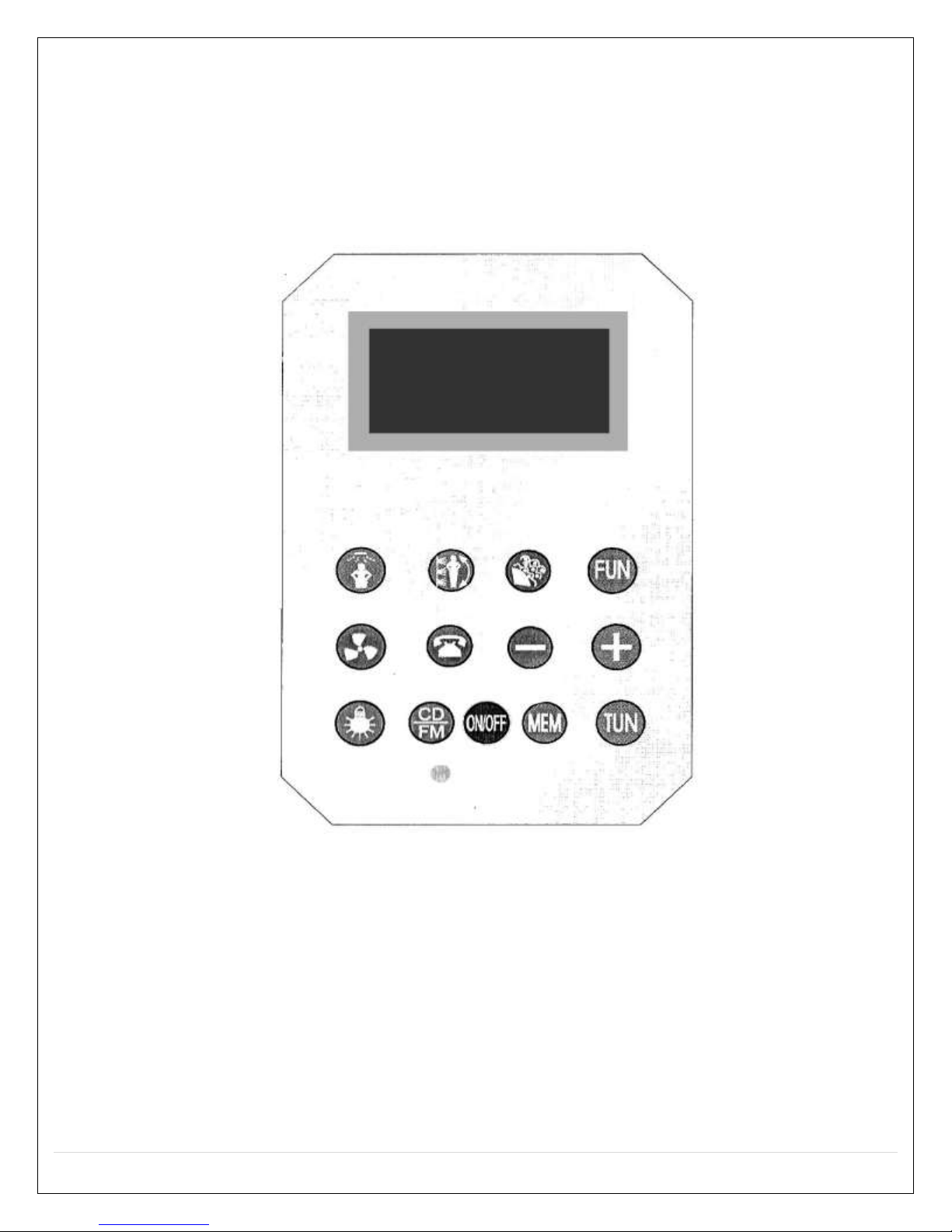
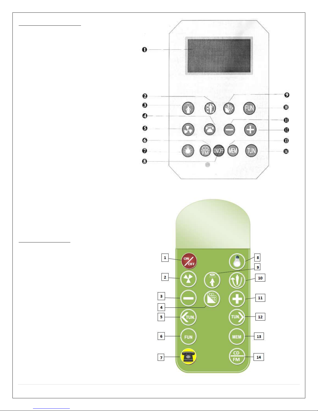
Main Control Panel
1. LCD
2. Massage Jets Function
3. Rainfall Shower Head
Function
4. Telephone Function
5. Fan Function
6. Radio / CD Function
7. Top Light Function
8. ON/OFF
9. Steam Function
10. Function Key
11. –Key
12. + Key
13. Band Storage Key
14. Radio Frequency
Remote Control
1. ON/OFF
2. Circulation Fan
3. Decrease Key
4. Steam Function
5. FM Tuning (-)
6. Function Key
7. Phone Key
8. Light Key
9. Rainfall Shower Key
10. Body Massage Jets
11. Increase Key
12. FM Tuning (+)
13. Memory Key
14. Radio / CD Switch

19 | P a g e
REV 03/2012
Introduction to Functions
1. ON/OFF
2. Light Lamp Function
3. Circulation Fan Function
4. Steam Function
5. Steam Time Function
6. Steam Temperature Function
7. Radio Function
Description of Functions
1. ON/OFF Key
Under ON state, press key on the panel or remote control key to start the
system, the top light will come on, and functions will be activated and illuminated on
the LCD display. The LCD display will show the environment temperature, press
key again to shut down the system.
Press other keys except on the panel or remote control key under standby
by and OFF state, the backlight of keys will be illuminated, if the system is not
turned on, the backlight will automatically shut-off in 30 seconds.
2. Light Lamp
Top light will be turned on when the system is activated, press on the control
panel or remote to turn on or off the top light.
Caution: The light power must be under 12V, and the power has to be less than or
up to 10W. The temperature system will be in danger is the light’s power is too high.
3. Circulation Fan
Press key on the panel to start the fan, the same icon will show on the LCD
panel. To shut off the fan, press key again.
4. Steam
Press key on the panel or remote control to control the steam system. When the
steam ON/OFF, LCD will display “S-ON” / “S-OF”. This will be displayed only for 5
seconds. See examples bellow:
When the steam generator does not have water, LCD display will flash “S-ON”, until
the steam generator is full or water or cut down, the flashing will stop and come back
to the original state. The other function also can be operated when the steam
machine does not have water and the LCD will redisplay the “S-ON” after operating
for about 4 seconds.
20 | P a g e
REV 03/2012
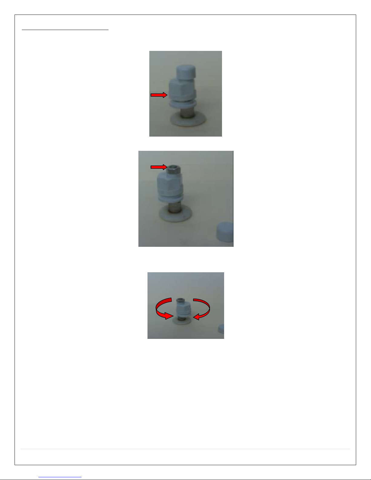
Caution: Setting aroma jar must screw the nut when the testing line from control
box and connect to the water level probe of Aroma jar. If the nut is too loose,
between the inside of the probe and the jar wall, the probe will not work during
testing. Without water creates a dangerous situation!
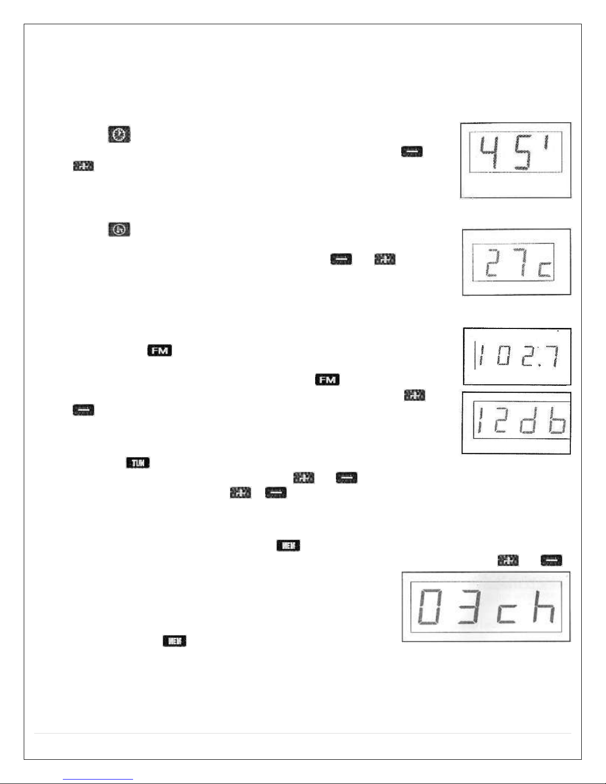
5. Steam Time Settings
Press key on the panel or remote control, LCD panel will
move into time setting state. See sample display. Press or
key to set duration. Time setting range is 1 –99 minutes,
default time is 45 minutes.
6. Steam Temperature Settings
Press key on the panel or control remote, LCD panel will
display the steam temperature setting state, see sample icon. To
increase or decrease the temperature, press or key. The
temperature range is between 25°C – 60°C, default temperature
is 45°C. When the temperature is more than the setting time
1°C will be cut down, if less than 1°C – the steam will come on.
7. Radio Function
Pressing the key on the panel or remote control will start
the radio function; LCD panel will display the current radio
frequency, see sample icon. Pressing the key for the second
time will turn off the radio. When the radio is on, press or
on the panel or remote control can adjust volume, and the
volume number will be displayed on the LCD panel, see sample
icon.
Pressing key on the panel or remote control can enter into or exit the FM
frequency. When in FM mode, press or on the panel or remote control can
adjust frequency. Holding or will skip to the next available frequency. If a
radio station cannot be found in 5 seconds, the system will exit the FM. The screen
will stop flashing.
When the radio is on, pressing the key on the panel or remote control can enter
into channel switch if the current radio is not in searching mode. Press or
to adjust channels, the range is 1 –25. If it cannot
find a radio channel within 2 seconds, it will turn back
to the channel display status. Entering in to channel
switch status, the channel will add 1, see sample.
When pressing more then 1.5 seconds, the
current radio station will be memorized as a favorite channel. The LCD panel will
flash the FM channel for hinting.
Table of contents
Other Steam Planet Plumbing Product manuals


