CONPO SDC-20A User manual

INSTRUCTION MANUAL
„Duo battery” Solar controller with remote
monitor, for yachting and caravaning
SDC-20A 12/24V + SDC-MT

1. PRODUCT DESCRITION
High quality controller with very small idle energy dedicaded for yachts, boats,
campers and other objects, where solar energy can be used - item is ideal for
smart control charge process for 2 batteries with choose of priority. This feature
allows user to reduce the risk of a lack of electricity to power eg. emergency
lighting, engine starting, radio communications and navigation by providing a
separate priority charging of the battery designated to power these devices.
Controller provides full information about the state of the system and occurring
defects. Remote monitor (IP 65 on the front side) allows for a full review of the
parameters and their modifications. It also has a LCD backlight with
programmable brightness and time, It can be placed in the most convenient
location for observation and operation (10m connection cable included).
2. FEATURES
◦The ideal controller for use on boats, campers, in the caravaning, and in other
applications. Most often it will be very useful for the possibility of independent
charging 2 batteries with prioritized charging, eg. Starter battery and battery
for general use, the battery for special purposes and the main battery and
others.
◦Remote Monitor allows you to see charging parameters and set some
parameters; there is also time and the temperature unit setting
◦Automatic identification of system voltage (12V or 24V)
◦The proportion of each accu charging power can be adjusted according to
your needs
◦PWM charge controller, precise temperature compensation
◦Protection against overload, short circuit, reverse polarity and reverse current
in PV panels
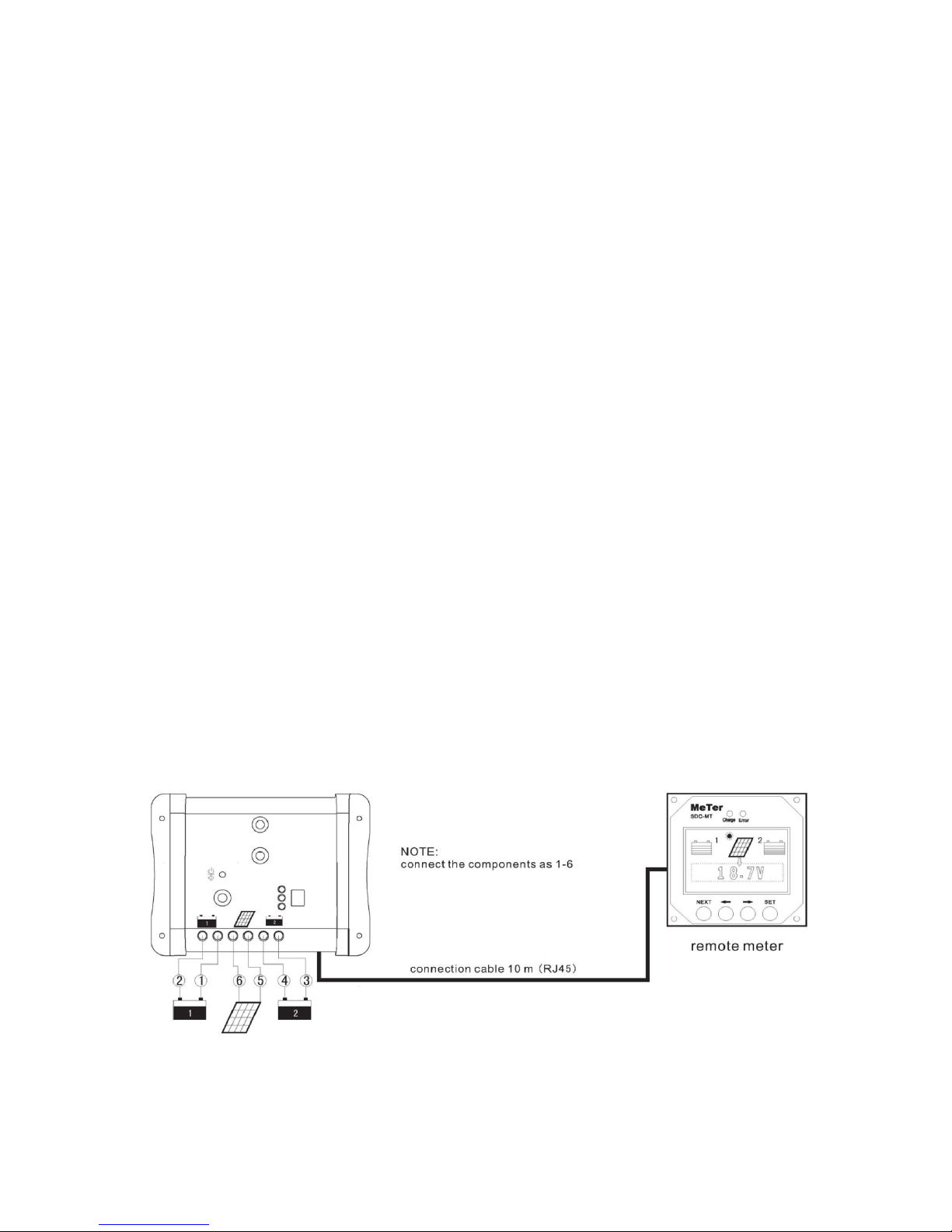
3. CONNECTION AND INSTALLATION
Fig 1. Diagram of controller and monitor connection


4. DIMENSIONS AND DIAGRAM OF CONTROLLER
Fig 3. Operation and visualization
Fig 4. The size and spacing of the mounting holes
5. SETTINGS
Settings are being indicated by three flashing LEDs, each LED is used for the
appropriate settings according to the table. After selecting the appropriate LED, the
settings button must be pressed for approx. 5s until the selected LED will flash.
While the LED is flashing choose another numer depressing the button on the display
corresponding to the selected parameter and leave the setting.
The selected number will be sent as a valid new setting.


8. TECHNICAL SPECIFICATION
Model SDC20
Max charging current 20A
System voltage 12/24V auto
Battery type SLD (szczelny) GEL FLD (zalewowy)
BOOST charge 14,2V; x2(24V) 14,4V; x2(24V) 14,6; x2(24V)
Absorption charge 14,4V; x2(24V) 14,6; x2(24V) 14,8; x2(24V)
Floating charge 13,7V; x2(24V) 13,7V; x2(24V) 13,7V; x2(24V)
Max PV voltage 30(V)
Battery voltage ranges 1~15V: x2(24V)
Self consumption 4mA at night, 10mA charge time
Monitor communication RJ45
Input terminals 6mm2
Ambient temperature -35°C ~ +55°C
Enclosure protection IP 22
Dimensions (BxGxH) / weight 136,6x43,3x104,6mm / 200g
9. REMOTE MONITOR SDC-MT
Monitor allows remote reading system parameters in the four loops, setting some
parameters, test system and deleting data:
- Loop 1: PV voltage, current Charge., Max current Charge., Accumulated energy (Ah),
% distribution of energy supplied to the battery 1 and battery 2
- Loop 2 (Battery No 1) voltage, voltage min, max voltage, energy accumulated(Ah)
- Loop 3 (Battery No 2) voltage, voltage min, max voltage, energy accumulated(Ah)
- Loop 4: Temperature, time

9.1. DIMENSIONS AND INSTALLATION OF MONITOR
4 holes. Ø 4.0 (0.16)
Dimensions in mm (inches)
10. MONITOR DISPLAY

Additional 2 LEDs above the display
Charging LED (left) lights green – charging; Fault LED (right) lights red - fault
10.1 OPERATING THE MONITOR
Buttons from left to right are marked as K1 (Next), K2 (Left), K3 (Right), K4 (Setting).
The display indications appear to indicate parameteres in the following order (loop from
1 to 4): system, battery No 1, battery No 2, other. We use K2 and K3 to view
parameters in the loop. Button K1 switches to the next loop (Fig. below)
Adjustable parameters are: temperature unit, the display backlight time, the brightness
of the backlight options for the review of the data, the clock (HH: MM). K4 button is
used to activate mode and saving changes, K2 and K3 to modify the parameter.
Settings
–Temperature: select ° C (degrees Celsius) or ° F (degrees Fahrenheit)
–Background lighting: any button launches backlight. In order to change time
settings of backlight press K4, select the desired time or other highlighted options
with K2, K3. The options shown in the diagram above are as follows: "OFF"
(always off), "ON" (on all the time), backlight time 30s or 20s or 10s or 5s. Press
K1 and proceed to the brightness settings, use can choose "FULL" (high
brightness), "HALF" (reduced brightness)
–Sequential reading data: Display data in each of the loops may be held-
OPERATE automatically - the choice "AUTO" (changed every 3 seconds or
manual change). We use the One Touch K1 to move to the next loop. In the case

of manual changes - Select "OFF" change of readings by use of K2, K3, the step
to the next loop K1
–Clock: If minutes (MM) or an hour (HH) flickers, respectively keys K2, K3 are
used to change the settings. Save settings and exit the setting mode by pressing
K4
Test system
At any time we can test correct working of the system by pressing keys K2 + K3.
Details of the diagram are below. If the LCD screen is not displayed, it means
that there is no connective-components between the controller and the monitor. If
it is properly connected, the appropriate data will be displayed. If the remote
temperature sensor is not connected monitor displays a thermometer symbol and
the message "NO". Detected monitor data/parameter are displayed. "OPEN"
means there is no battery or excessive voltage value. Given messages and data
parameters are displayed in sequence at 0.5s (diagram below)
Deleting parameters
When installing a new system, at any time of installation erasing of stored in the
system memory data can be done.
Parameters that will be erased are:max, min, Ah. After a while you press K3 + K4
replace data reset.
At the same time start of a new aggregation Ah and registration max and min will
start.
10.2 Technical specifications
Rated voltage: 12V, minimum voltage 8V
Power consumption at 100% backlight: <23mA
Power consumption at reduced backlight: <20mA
Backlight and LED off: <17mA
Ambient temperature: -40°C~+60°
Operation on LCD: -10°C~+40°C
RH: up 100% (without condesation)
Communication cable RJ45 (10m)
Front enclosure protection: IP 68
10.3 General remarks

If the symbol is displayed please check:
1. If the battery is disconnected, if there is no break in the circuit or if there is too
high voltage
2. If gharging current is not exceeded
4. If there is no short circuit in the PV panel
If the fault is repaired a symbol automatically stops to show
10.4 Communication Port: if the monitor is running on battery power or own supply
and there is a break in communication, display will show "OFF". After pressing any
button there is no answer. If communication returns then automatically monitor returns
to the display.
Battery status: Each displayed "bar" bar graph corresponds to 20% of full charge state
charging battery. On the other hand, any flashing beam corresponds to the
volume 1~19%. This means that when the first bar lights and the next flashing it is the
capacity of battery 21 ~ 39%. You have to remember that this calculation is simplified
because it is based on battery voltage and not its real capacity. 100% corresponds to
voltage of full charge, and 0% over-voltage discharge.The energy accumulated (Ah)
corresponds to the charge accumulation and is calculated every 1 min. The calculation
results are not very accurate when loading runs with a low current. The minimum
indication is 1 Ah witch means charging 1A current for 1 hour.
11. ENVIRONMENTAL PROTECTION
The device is subject to the WEEE Directive 2002/96/EC. This symbol indicates
that the product must be disposed of separately and should be delivered to the
appropriate point collector. It should not be disposed of with household waste.
For more information, please contact your company or local authorities
responsible for waste management.
SB: 2017-02-01
Table of contents